Numerical investigation on the influence of rope cutter installation on water flow around a ship’s propeller
Copyright © The Korean Society of Marine Engineering
This is an Open Access article distributed under the terms of the Creative Commons Attribution Non-Commercial License (http://creativecommons.org/licenses/by-nc/3.0), which permits unrestricted non-commercial use, distribution, and reproduction in any medium, provided the original work is properly cited.
Abstract
Research and development of marine equipment aimed at improving safety at sea has led to a significant reduction in the occurrence of marine accidents. Studies have revealed that installing a rope cutter device would prevent propeller entanglement, which is a major cause of accidents for small ships sailing in coastal regions. This study investigates the effects of rope cutter installation on the pressure distribution, flow streamlines, velocity vectors, cavitation, and thrust force produced by the propeller using the computational fluid dynamics (CFD) approach. ANSYS Fluent, CFD software was used in this study and simulations were conducted under open sea conditions at a maximum continuous rating (MCR) using actual ship propeller dimensions. As a result, rope cutter installation led to a slight reduction of water flow velocity behind the propeller, lower vapor volume fraction by 5.02%, and lesser turbulence in the flow behind the propeller. There were no visible differences in the pressure distribution around the propeller. The average thrust force produced by the propeller was increased by 1.97% after rope cutter installation while the torque required to rotate the propeller with the rope cutter was higher by 0.965%. The findings indicate that the installation of a rope cutter has no adverse impact on the propeller's operation. This research revealed extra positive effects, including a decrease in vapor formation, water circulation behind the propeller, and a slight increase in the propeller's thrust force.
Keywords:
Marine accidents, Rope cutter, Marine debris, Computational fluid dynamics, Propeller1. Introduction
Human activities at sea are continuously increasing. These activities, such as fishing, leisure, sports, and shipping in general, result in increased amounts of litter at sea. Marine litter poses a navigational danger, especially to small ships sailing near the coastline. The debris leads to problems such as propeller entanglement, capsizing of ships, and schedule delays that arise due to time wasted to repair the entangled propeller. Repairing an entangled propeller is a very expensive and risky task. Once the propeller is clogged, the ship will have to be towed to the dry dock for repairs and a detailed inspection of the ship components surrounding the propeller. A more expensive overhaul may be required in case of damage to the stern tube or the rudder. However, if it is suspected that the entangling material did not cause serious damage, then a diver is sent underwater to remove the entangling materials. Working underwater is a risky practice that might lead to secondary accidents, such as the death of divers if safety is not well observed.
There are several pieces of literature about marine accidents resulting from propeller entanglement [1]-[4]. The invention of the rope cutter has played a vital role in reducing propeller entanglement accidents. A rope cutter is a marine safety device installed on the propeller shafts to cut marine debris flowing toward the propeller, thereby preventing entanglements [5]. It is made of rotating blades and one fixed blade; which is kept in position by the holding block mounted on the stern tube housing. The number of rotating blades can be varied to improve the cutting performance. The size of the rope cutter is varied depending on the ship’s propeller and the propeller shaft size.
Evaluation of the effectiveness of rope cutters has been studied in detail in literature [3]. The study, which included a survey, revealed that the average number of accidents resulting from propeller entanglement was reduced by 78% after rope cutter installation. Lee et al. [6] Studied the effects of the rope cutter’s cutting action on the propeller shaft and the entire ship's body vibration; as a result, there was an insignificant change in the vibration results of the ship with and without the rope cutter. Kim et al. [7] conducted a finite element analysis to determine if the properties material used for making rope cutters lay within the acceptable factor of safety when operating under different loads. The result showed that the rope cutter materials were designed to break off once the cutter cannot cut the marine debris, which is very important to prevent the destruction of the ship's propulsion system because of a clogged rope cutter.
This study employs ANSYS fluent simulation software to investigate the effects of a 4-blade rope cutter installation on the pressure distribution, flow streamlines, velocity vectors, cavitation, and thrust force produced by the propeller using the computational fluid dynamics (CFD) approach. The study was conducted under open sea conditions at a maximum continuous rating (MCR). Two simulation cases were conducted for a propeller with and without a rope cutter and the results compared. The simulation model used in this study was validated by Nyongesa et al. [8] where, the authors used a model rope cutter in a test tank condition. The rope cutter used contained two rotating blades and one stationary blade installed on a model shaft and a model propeller. In this study, an actual rope cutter, composed of four rotating blades and one stationary blade with an improved design installed on a 990-ton ship, is investigated under the open sea condition. All the model settings were maintained as in the validated literature. However, the input parameters, namely the ship's speed and the propeller speed, were changed to match the current ship’s MCR. The propeller design and the rope cutter sizes were adjusted to match the ship dimensions under study.
2. Computational fluid dynamics analysis
2.1 Computational domain
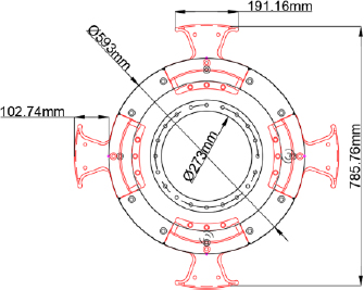
A 3-dimensional geometry was generated using AutoCAD 2020 software by Autodesk Inc. The 3D geometry was built in a way such that the propeller was at a depth similar to the actual ship’s draft. The domain was divided into two parts, namely the rotating and the stationary domain. The rotating domain enclosed the propeller and the rotating part of the rope cutter, while the rest of the computational domain was set as the stationary domain. The domain was made as large as possible to minimize the interference of the wall effects on the flow characteristics. The principal dimensions of the propeller used consisted of 4 blades with a hub and overall diameters of 593 mm and 2500 mm, respectively. On the other hand, the principal dimensions of the rope cutter were shown in Figure 1.
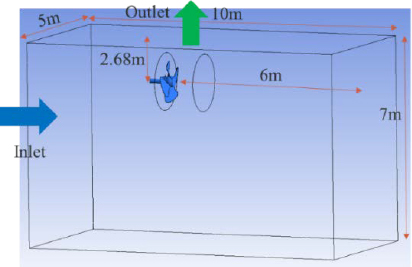
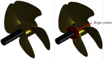
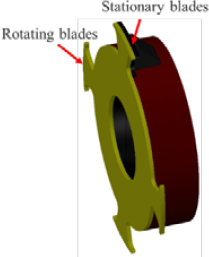
Figure 2 shows the computational domain, respective dimensions, and boundaries. Figure 3 shows a 3D propeller geometries without and with a rope cutter used during simulations. For clarity, a 3D rope cutter detailed figure is shown in Figure 4.
2.2 Computational mesh
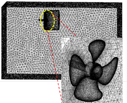
ANSYS Fluent provides a powerful meshing platform for computational domain preprocessing. This meshing tool was used for meshing during this study. A local sizing technique with an element size of 0.01m was used for meshing the rotational domain, while a global mesh of 0.1m was used for the static domain. The mesh in the region near the propeller walls was further refined to using a smaller mesh size of 0.004 to ensure accurate prediction of flow characteristics near the propeller and rope cutter walls which are the most vital points of focus. Detailed mesh properties and a diagram showing the computational mesh are shown in Table 1 and Figure 5, respectively.
2.3 CFD setup
Due to the inaccessibility, expensive, and sometimes dangerous nature of experimental approaches, it is now practical to use CFD in various scientific research. The CFD approach has proven to be a powerful tool in solving research problems that would have been impossible using an experimental approach. In propeller flow analysis studies; there are very many researchers that have employed the CFD approach and yielded excellent results. Sezen et al. [9] performed a numerical investigation of marine propeller underwater radiated noise using an acoustic analogy, they further analyzed the effects of eddy viscosity turbulence models of propeller flow numerical studies they compared propeller performance characteristics with experiment results which agreed well. Krishna et al. [10] used ANSYS fluent to study the fluid-structure interaction around a marine propeller, propeller performance characteristics agreed well with the experimental results. Ansys Fluent CFD software in particular has been used in various pieces of literature [8][11]-[14] and shown very good results.
In this study, the K-epsilon model was enabled to simulate the flow turbulence around the propeller. K-epsilon is a robust and economical model with reasonable accuracy over a wide range of turbulence flows [15]. The solver was set to pressure based option in which the constraint of mass conservation of the velocity field is achieved by solving a pressure equation. The solved pressure equation is derived from continuity and momentum equations in such a way that the velocity field, corrected by the pressure satisfies the continuity [15]. Pressure and momentum were set to second-order upwind, while turbulence kinetic energy and the dissipation rate were set to the first-order upwind scheme. Simulation convergence was ensured by setting the convergence criteria of 0.001 for continuity, velocity, k, and epsilon. Convergence was then confirmed by observing the residuals. In the boundary conditions, specific values and boundary properties were used, as shown in Table 2. The simulation model summary is shown in Table 3.
ANSYS fluent solver was used for the calculations. The time step size was set at 0.001s throughout the entire simulation. CFD calculations were conducted for 15 propeller revolutions in each case to ensure flow stability before analysis. Simulation iterations were set to 50 however, by observing the residuals, convergence was achieved after 40 iterations.
3. Results
3.1 Flow streamlines
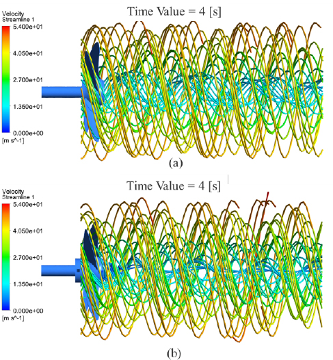
Figure 6 shows the water flow streamlines behind propeller without rope cutter and propeller with rope cuter in (a) and (b) respectively. The size of the rope cutter is so small as compared to the propeller. However, there are noticeable differences between the streamlines for the propeller with and without the rope cutter. For the propeller without rope cutter, the velocity of water behind the propeller, especially around the propeller hub, can be seen to be slightly higher than compared to the propeller with rope cutter installed.
There is also a wider vortex region behind the propeller without the rope cutter. The difference in the flow velocities can be attributed to the rotating effect of the rope cutter blades, which creates a slight resistance to the inflowing water.
According to Bernoulli’s principle, which relates the fluid flow velocity and pressure suggests that, an increase in the speed of a fluid simultaneously occurs with a decrease in pressure. High water velocities behind propellers are undesirable since it results to low local pressures, which can lead to cavitation inception [16]. Installing rope cutters reduces the velocity of water behind the propeller.
3.2 Vapor volume fraction
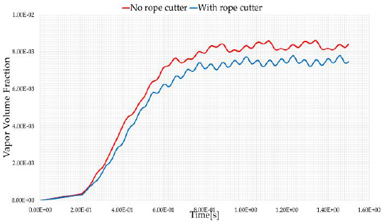
Cavitation is the formation of vapor-filled cavities in the liquid when the local pressure decreases below the liquid’s vapor pressure. In ANSYS Fluent simulation software, cavitation formation is analyzed as vapor volume fraction. In this simulation, the vapor volume fraction was analyzed on the suction side of the propeller. Figure 7 (a) and (b) show the vapor volume fraction contours obtained while Figure 8 shows a transient graphical representation of the vapor volume fraction.
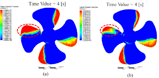
Volume fraction contours results for (a) propeller without rope cutter and (b) propeller with rope cutter
Vapor volume fraction contours results show a significant reduction in the amount of vapor formed behind the propeller without a rope cutter. Analysis of transient vapor formation during the simulation also shows that a higher amount of vapor fraction was formed in the case of a propeller without a rope cutter. Calculation of vapor fraction at stable conditions revealed that rope cutter installation could reduce the amount of vapor fraction formed by 5.02%. Besides preventing propeller entanglements, rope cutter has other desirable benefits, including a reduction of vapor formation (cavitation) during propeller operation. This is because, as the rope cutter rotates, it reduces the inflow of water near the propeller hub because of the resistance caused by the rotating action of the blades. Reduced velocity increases the local pressure above vapor pressure, preventing phase change from liquid to vapor.
3.3 Velocity vectors
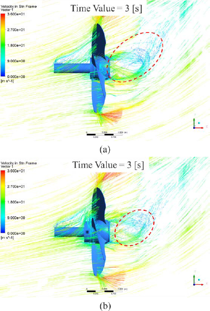
In CFD, velocity vector results are used to observe the fluid flow direction and magnitude in detail. During this study, velocity vector analysis was also conducted. Figure 9 shows the velocity vector results for (a) propeller without rope cutter and propeller with (b) rope cutter.
From the velocity vector results, the flow characteristics in the front and back side of the propeller are visualized. A smooth flow is observed on the pressure side of the propeller without the rope cutter, whereas there is a slight turbulence on the pressure side of the propeller with the rope cutter resulting from the rotating action of the rope cutter propeller blades. In the suction side of the propeller, a more turbulent flow is experienced behind the propeller without a rope cutter. There are larger circulations that progress through a longer distance downstream. Rope cutter installation reduces flow turbulence behind the propeller. It’s a well-known fact that turbulent flow exhibits high noise levels. If turbulence behind the propeller is reduced, then propeller operation will be quieter. This is a desirable benefit, especially with the growing need to reduce noise pollution resulting from marine propellers. A comparison of the thrust and torque produced on the propeller blades at a stable condition was analyzed and compared. As a result, an average thrust force of 26289.35N and 26807.253N was recorded for propeller without and with rope cutter, respectively. The thrust force produced on the propeller walls was increased by 1.97% after rope cutter installation. On the other hand, an average torque of 10458.45N-m and 10559.37N-m was recorded for the propeller without and with rope cutter, respectively representing a 0.965% increase in torque. This means that to overcome the weight and resistance resulting from the rope cutter’s rotating action, an additional torque of 0.965% is needed. This is an undesirable effect of installing rope cutters. However, the benefits of installing a rope cutter overrides the negative effects, since the additional required torque is negligible. Because of these negative effects, it is recommended that rope cutter manufacturers select suitable materials with high durability and lower weight to minimize the need for additional torque. The rope cutter shape can as well be optimized to reduce the resistance caused by the rotating blades.
4. Conclusion
In this study, ANSYS fluent software has been used to investigate the effects of an improved design, a four-blade rope cutter on the propeller operation in open sea conditions and MCR engine conditions. Various fluid flow characteristics around the propeller, including flow streamlines, vapor volume fraction, velocity vectors, thrust force, and torque, were analyzed for a propeller case with and without a rope cutter. The results showed that rope cutter installation has more beneficial effects apart from reducing marine accidents. From the results obtained in this study, it can be concluded that:
- • The velocity of the water behind the propeller was reduced, as demonstrated by the streamlines, particularly for the streamlines along the propeller hub due to the rotational action of the rope cutter.
- • Installation of a rope cutter decreased the formation of vapor on the propeller blades, otherwise known as cavitation, by a noteworthy 5.02%, an imperative factor for the durability of the propeller.
- • A study of the velocity vectors behind the propeller showed a smoother flow with a rope cutter. A decrease in turbulence is necessary to reduce propeller noise.
- • The installation of the rope cutter brings about a slight increase in the torque and thrust force of the propeller of 0.965% and 1.97%, respectively.
Rope cutter device installation has proven its ability to reduce marine accidents resulting from propeller entanglements by 78% in previous studies. This study reveals additional beneficial effects that can be achieved by installing a rope cutter. The study also eliminates the uncertainties of ship-owners and operators regarding whether rope cutter installation could cause harm to the propeller operation. Rope cutter installation will not only reduce propeller entanglement risks, but will also help to improve propeller operation and durability.
Author Contributions
Conceptualization, A. J. Nyongesa and S. Yeo; Methodology, A. J. Nyongesa; Software, A. J. Nyongesa; Validation, A. J. Nyongesa and S. Yeo; Formal Analysis, Y. Y. Sul; Investigation, A. J. Nyongesa and S. Yeo; Data Curation, Y. Y. Sul; Writing—Original Draft Preparation, A. J. Nyongesa; Writing—Review & Editing, S. Yeo; Visualization, A. J. Nyongesa; Supervision, S. Yeo; Project Administration, S. Yeo; Funding Acquisition, S. Yeo.
References
-
D. O. Cho. “Challenges to marine debris management in Korea,” Coastal Management, vol. 33, no. 4, pp. 389-409, 2005.
[https://doi.org/10.1080/08920750500217559]

- K. Hall. “Impacts of marine debris and oil,” Economic Social Costs to Coastal Communities, Publication of Kommunenes Internasjonale Miljøorganisasjon, 2000.
-
W. Lee, J. Choi, J. Kim, W. Lee, and J. Kim, “A Study on current status of entanglement accident and user satisfaction survey for ship with rope cutter in domestic,” Journal of Fisheries Marine Sciences Education, vol. 31, no. 6, pp. 1536-1543, 2019 (in Korean).
[https://doi.org/10.13000/JFMSE.2019.12.31.6.1536]

- S. Takehama. “Estimation of damage to fishing vessels caused by marine debris, based on insurance statistics,” In Proceedings of the Proceedings of the Second International Conference on Marine Debris, 1990.
-
H. Lee, J. -S. Oh, S. -H. Choi, “Development of an underwater rope-cutter device and controller for removal of propeller and shaft foreign material for small vessel,” Journal of the Korean Society of Marine Environment Safety, vol. 25, no. 7, pp. 927-935, 2019.
[https://doi.org/10.7837/kosomes.2019.25.7.927]

-
W. -J. Lee, J. -H. Kim, S. -H. Jang, K. -W. Lee, B. -Y, Kim, W. -K. Lee, B. -S. Rho, J. -S. Kim, and J. -H. Choi, “A study on safety and performance of rope cutter for ship's propeller,” Journal of the Korean Society of Marine Environment & Safety, vol. 24, no. 4, pp. 475-481, 2018.
[https://doi.org/10.7837/kosomes.2018.24.4.475]

-
J. -S. Kim, Y. Seul, D. -Y. Lee, K. Park, T. H. Kim, J. -H. Choi, and W.-J. Lee, “A study on the structural stability and effectiveness of rope cutter for ship's propeller,” Journal of the Korean Society of Marine Environment & Safety, vol. 27, no. 4, pp. 550-556, 2021.
[https://doi.org/10.7837/kosomes.2021.27.4.550]

-
A. J. Nyongesa, V. C. Pham, S. H. Yoon, W. -S. Kwon, J. -S. Kim, D. N. Ngo, J. -H. Choi, Y. -Y. Sul, W. -J. Lee, “Investigation of the effect of rope cutter on water flow behind ship propellers based on CFD analysis,” Machines, vol. 10, no. 5, p. 300, 2022.
[https://doi.org/10.3390/machines10050300]

-
S. Sezen, T. Cosgun, A. Yurtseven, and M. Atlar, “Numerical investigation of marine propeller underwater radiated noise using acoustic analogy Part 2: The influence of eddy viscosity turbulence models,” Ocean Engineering, vol. 220, p.108353, 2021.
[https://doi.org/10.1016/j.oceaneng.2020.108353]

-
V. R. Krishna, S. P. Sanaka, N. Pardhasaradhi, and B. R. Rao, “Hydro-elastic computational analysis of a marine propeller using two-way fluid structure interaction,” Journal of Ocean Engineering & Science, vol. 7, no. 3, pp. 280-291, 2022.
[https://doi.org/10.1016/j.joes.2021.08.010]

-
G. Santosh Kumar and B. Mahesh, “Static and fluid analysis of a marine propeller,” Recent Trends in Product Design and Intelligent Manufacturing Systems: Select Proceedings of IPDIMS 2021, pp. 335-343, 2022.
[https://doi.org/10.1007/978-981-19-4606-6_32]

-
M. M. Uddin, M. P. Hossen, M. M. Jahan, and M. I. Islam, “Structural analysis of composite propeller of ship using FEM,” In Proceedings of the AIP Conference Proceedings, p.030001, 2021.
[https://doi.org/10.1063/5.0037760]

- S. S. Wankhede, “Numerical modelling and fluid-structure interaction of composite propeller foil using ANSYS,” 2021.
-
K. Yu, P. Yan, and J. Hu. “Numerical analysis of blade stress of marine propellers,” Journal of Marine Science Application, vol. 19, pp. 436-443, 2020.
[https://doi.org/10.1007/s11804-020-00161-3]

- ANSYS. ANSYS fluent theory guide 19.1, 2019.
-
N. Yilmaz, X. Dong, B. Aktas, C. Yang, M. Atlar, P. A. Fitzsimmons, “Experimental and numerical investigations of tip vortex cavitation for the propeller of a research vessel, “The princess royal”, Ocean Engineering, vol. 215, p. 107881, 2020.
[https://doi.org/10.1016/j.oceaneng.2020.107881]


