Exploring the reduction of sloshing in a rectangular tank with a baffle using coupled Eulerian-Lagrangian analysis

Copyright © The Korean Society of Marine Engineering
This is an Open Access article distributed under the terms of the Creative Commons Attribution Non-Commercial License (http://creativecommons.org/licenses/by-nc/3.0), which permits unrestricted non-commercial use, distribution, and reproduction in any medium, provided the original work is properly cited.
Abstract
The sloshing problem is a critical issue in the design of liquid cargo carriers, especially for partially filled tanks. The violent change in the free water level inside a tank caused by ship motions in rough sea conditions generates a large impact on the tank walls, which leads to structural damage to the cargo containment system in the cargo tank. Therefore, several studies have been conducted to find an appropriate method for reducing sloshing impact damage. In this study, the effect of baffles on sloshing impact loads was numerically investigated using the coupled Eulerian-Lagrangian technique, which is generally applied to fluid-structure interaction analysis by combining the advantages of the Eulerian and Lagrangian formations. Two-dimensional numerical simulations have been performed and compared with previous research results to investigate the effect of vertical and horizontal baffles at various positions and lengths.
Keywords:
Sloshing, Coupled Eulerian-Lagrangian method, Vertical baffle, Horizontal baffle, Fluid-structure interaction1. Introduction
The sloshing problem in partially filled tanks is a critical issue in the design of liquid cargo carriers. When a liquid carrier operates in rough seas, violent free-water changes in the tank caused by sloshing can generate a large impact load on the tank wall, potentially causing structural damage inside the tank or deteriorating the motion performance of the ship. Therefore, many studies have been conducted over the past few decades to understand the phenomenon of sloshing and how to effectively suppress it [1]. Lu et al. [2] conducted experiments to investigate the changes in sloshing pressure for various filling levels in square tanks. Kim et al. [3] used potential theory to calculate the sloshing speed profile of a square tank in the horizontal direction. Ahn et al. [4] analyzed the database from a sloshing model experiment using an artificial neural network and developed a prediction model. Pilloton et al. [5] used the smoothed particle hydrodynamics model to investigate the sloshing phenomenon inside an LNG fuel tank.
Among the various methods for suppressing sloshing, installing baffles inside the tank is known to be effective. Many studies have been conducted to investigate the effect of baffles on sloshing. Celebi and Akyildiz [6] conducted experiments to study the nonlinear sloshing phenomenon in square tanks with vertical baffles installed. They found that the effect of the baffle was greatly influenced by the height, amplitude, and frequency of the liquid. Chu et al. [7] used experiments and numerical methods to study the sloshing phenomenon in square tanks with multiple baffles. Guan et al. [8] conducted a numerical study using a nonlinear boundary element method to investigate the effect of baffles in a three-dimensional rectangular tank. Jung et al. [9] used computational fluid dynamics (CFD) to study the sloshing phenomenon in square tanks with vertical baffles of various lengths.
Recently, as computational performance has improved and efficient numerical analysis techniques have been developed, more research has been conducted to quantitatively understand the effect of baffles using various numerical methods. Many researchers have applied the CFD technique to study the reduction of sloshing by baffles. However, the application of the coupled Eulerian-Lagrangian (CEL) technique, which models fluids as Eulerian domains using finite element methods and structures as Lagrangian domains to enable efficient interaction between them, is rare in the study of sloshing problems, although it is gaining popularity due to its relatively fast computation [10]. This method may not accurately consider turbulence effects, but it can be effectively used to compare relative behaviors among different baffles.
In this study, the effect of various types of baffles on sloshing was investigated using the CEL technique. The following two types of baffles were compared:
- - Rigid vertical baffles at different numbers and heights
- - Rigid horizontal baffles at different positions and lengths
A two-dimensional model was used to compare the relative sloshing behavior among different baffles. The baffles and tank were modeled as rigid bodies. The baffles were installed in square tanks of the same size and shape to quantitatively compare their effects.
This study quantitatively compared the effects of various types of baffles under the same conditions and efficiently applied the CEL technique to the process. This distinguishes it from previous studies [7][8][9]. Based on the results of this study, it is expected that the effect of baffles of different shapes and lengths can be efficiently determined.
2. CEL method
In order to perform the sloshing simulation of the fluid inside the tank, the deformation of the fluid must be effectively modeled, and the contact between the fluid and structure must also be properly implemented. Since traditional finite element methods based on Lagrangian domains cannot effectively express excessive deformation of elements, Eulerian-based finite element methods in which matter moves within fixed nodes in space or arbitrary Lagrangian-Eulerian techniques can be applied, which respond well to material movement. In the former case, the movement of the material is free, whereas in the latter case, since the node must move along the material, it is difficult to implement a fast deformation, and it takes a long time to interpret the results.
Figures 1 and 2 show the difference between the Lagrangian mesh and Eulerian mesh, respectively. In a Lagrangian mesh, nodes can accurately track and define the boundaries of matter because they travel with matter, but it is difficult to implement large deformations. Conversely, in the Eulerian mesh, the node does not move, but only the material inside moves; therefore, the material is free to move regardless of the mesh.
The CEL technique combines the Eulerian technique and Lagrangian technique implemented in the commercial program ABAQUS. The fundamental conservation equations of mass and momentum are presented in Equations (1) and (2). To express these equations in Eulerian formulation, the relation between material and spatial-time derivatives of φ should be determined, as in Equation (3).
| (1) |
| (2) |
| (3) |
Here, ρ = density, v = material velocity, σ = Cauchy stress, b = body force, and φ = arbitrary solution variable.
In the case of fluids, the fluid can move freely inside the element based on the calculation of the Eulerian volume fraction (EVF). Each Eulerian element is expressed as a percentage depending on the degree of filling of the material in the element. That is, if there is no substance in the corresponding element, the EVF is 0, and if it is full, the EVF is 1. In the case of solids, traditional Lagrangian techniques are applied as they are. In ABAQUS, the contact between Eulerian and Lagrangian substances is solved by the 'General contact' technique. In this method, the Lagrangian element can move freely inside the Eulerian element without contact with the mesh or nodes between the two materials. Instead, when the Lagrangian element meets the boundary of the EVF calculated inside the Eulerian element, contact between the two substances occurs.
3. Benchmark test
3.1 Target model for benchmark test
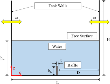
In this study, a benchmark test based on the previous research of Yu et al. [11] was performed to verify the results of the sloshing simulation using CEL. As shown in Figure 3, the rectangular tank with L = 1 m and H = 1 m was set to a depth of hw = 0.5 m, and baffles with varying lengths and a thickness of t = 0.01 m were installed in the center of the tank. The different lengths of the baffle applied for the analysis are shown in Table 1. The excitation amplitude was set to 0.002 m, and the excitation frequency was set to ω = 5.316 rad/s. Here, the excitation frequency corresponds to the lowest-order eigenfrequency of the model without the baffle.
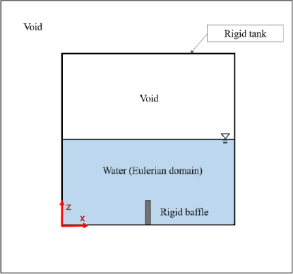
Figures 4 and 5 show the shape of the target tank modeled by applying the CEL technique. For efficient analysis, structures, i.e., tanks and baffles, were modeled as rigid bodies, and the fluid parts were all modeled in the Eulerian domain. Due to the characteristics of the CEL technique, the outside of the tank was surrounded by an Eulerian path and set as a void in order to make the water move naturally. An equation of state (EOS) can be employed to explain the hydrodynamic characteristics of water. ABAQUS utilizes the Mie–Gruneisen EOS with the linear Us-Up Hugoniot form to achieve this. In this study, the Us-Up state equation was applied to model water, and the applied physical properties are listed in Table 2 [11].
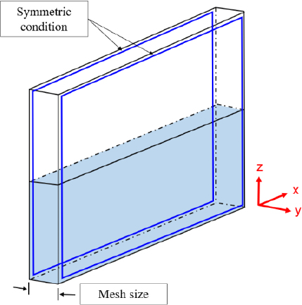
Since the purpose of this study is to understand relative reduction of sloshing according to different baffles, the entire model was modeled in two dimensions, as shown in Figure 5, for efficient simulation. The thickness of the whole model was equal to the size of the element; hence, only one element was built in the width direction, and a symmetrical condition was applied to the element in the width direction.
3.2 Mesh sensitive study
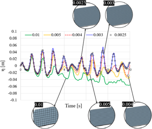
In finite element analysis, it is very important to determine a mesh of appropriate size because the size of the mesh can greatly affect the accuracy of the analysis results and the efficiency of the calculation. In this study, mesh sensitivity evaluation was performed on the baffle-free model, as shown in Figure 6, and the optimal mesh size was determined.
A model with five mesh sizes of 0.010, 0.005, 0.004, 0.003, and 0.0025 m was built, and the mesh sizes of water, void, and the tank were applied equally; the excitation frequency was assumed to be 1.2 times the lowest natural frequency.
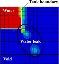
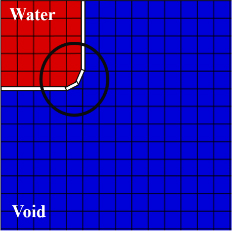
The analysis results of 0.010 and 0.005 m to which the largest mesh was applied showed that the height of the water surface gradually decreased as the simulation time elapsed. This is an error in numerical analysis, and as shown in Figure 7, the interface between water and the tank does not accurately contact each other, resulting in water flowing out of the tank. To solve this problem, a mesh of sufficiently dense size was used, and the boundary of the tank was rounded, as shown in Figure 8, such that the water and the tank could be in perfect contact. The mesh sizes of 0.003 m and 0.0025 m showed almost the same analysis results. Finally, in this study, the mesh of size 0.0025 m was set as the default mesh.
3.3 Result of benchmark test
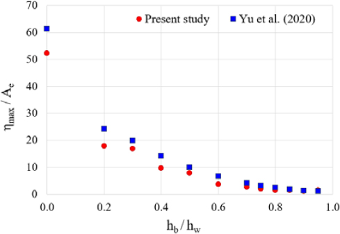
The series simulations were performed under the same conditions as the analysis performed by Yu et al. [11], that is, by applying the final determined model and mesh size through the mesh sensitivity evaluation, as described in Section 3.2. A finite element model was created and analyzed according to the length of the vertical baffle (Table 1), and the results are illustrated in Figure 9. The x-axis represents the ratio of baffle length to water level (hb/hw), and the y-axis represents the ratio of maximum wave amplitude to excitation amplitude (ηmax/Ae). Upon comparison with the results obtained by Yu et al. [11], it can be seen that the two results show good agreement overall. Considering that the analysis model used in this study is two-dimensional, this analysis method can be employed to investigate the relative effect of baffle.
4. Finite element analysis based on CEL method
A two-dimensional rectangular tank and an internal baffle were modeled using the method introduced in Section 3 to investigate the effect of baffle according to the length and number of vertical baffles and the location and length of horizontal baffles. The tank has a length of L = 0.5 m, a width of W = 0.3 m, a height of H = 0.4 m, and an initial depth of hw = 0.08 m. Displacement was applied using a sine wave as shown in Equation (4) to generate harmonic surge excitation in the tank. At this time, the applied excitation amplitude Ae is 0.015 m, and the frequency is set to ω = 6.911 rad/s, which is 1.3 times the lowest wave eigenfrequency.
| (4) |
Ae = Excitation amplitude (m), ω = Excitation frequency (rad/s)
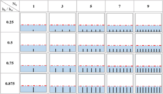
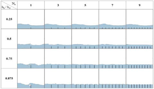
Figure 10 shows the analysis cases used to investigate the effect of vertical baffles. The analysis case was set by combining the lengths hb = 0.02 m, 0.04 m, 0.06 m, and 0.07 m (i.e., hb/hw = 0.25, 0.50, 0.75, 0.875) of the vertical baffle, with the number of vertical baffles Nb = 1, 3, 5, 7, 9. We can see that as the number of baffles increases, the gap between baffles decreases.
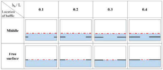
As shown in Figure 11, the horizontal baffles were attached to the side of each wall, and the length (hb) of the baffle and position of the baffle were set differently. The length of the baffle was set to 0.050 m, 0.010 m, 0.015 m, and 0.020 m (i.e., hb /L = 0.1, 0.2, 0.3, 0.4), and the location of the baffle was categorized as: installed at the initial water level and installed at half the initial water level.
5. Analysis result and discussion
5.1 Effect of vertical baffles
Simulation was performed on 20 analysis cases, as shown in Figure 10, and the sloshing behavior for the maximum amplitude (ηmax) under each condition is shown as a snapshot in Figure 12.
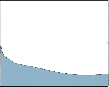
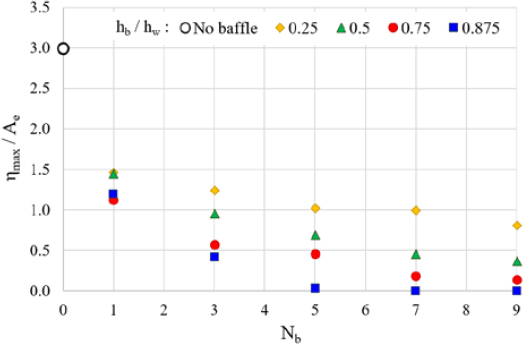
For comparison purposes, the analysis result for the no-baffle case is presented in Figure 13. Under the same conditions, it may be confirmed that the smaller the number of baffles and the shorter the length of the baffle, the larger is the maximum amplitude. As shown in Figure 14, in order to quantitatively compare the effects of baffles, the relationship between the length of baffles and maximum amplitude (ηmax/Ae) for the different numbers of baffles is determined. Overall, it can be seen that the sloshing behavior decreases as the number of baffles increases and the length increases. However, when a certain length and number of baffles are reached (i.e., hb/hw = 0.875 and five baffles), the additional baffle installation has no effect.
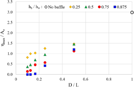
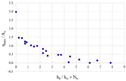
In Figure 15, instead of the number of baffles on the x-axis, the result is shown in terms of the ratio D/L of the distance between the baffles (or the distance between the baffles and tank) to the tank length. Overall, as the interval D increases, a large amplitude is shown, and if D/L is less than 0.17 with a baffle length of hb/hw = 0.875, waves are barely generated. In order to compare the effect of the number and length of baffles at once, the relationship between the sum of the cross-sectional areas of the baffles and maximum amplitude is determined. Therefore, in Figure 16, the x-axis is expressed as the value hb/hw × Nb obtained by multiplying the length of the baffle with the number of baffles. It can be seen that the maximum amplitude decreases as the sum of the cross-sectional areas of the baffles increases, and the dimensionless results so derived are considered to be useful for practical design applications in regards to different lengths and numbers of vertical baffles. Table 3 summarizes the effect of the vertical baffles.
5.2 Effect of horizontal baffles
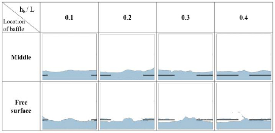
Simulation is performed on the eight analysis cases, as shown in Figure 11, and the sloshing behavior for the maximum amplitude (ηmax) under each condition is shown as a snapshot in Figure 17.
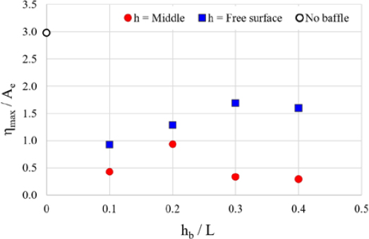
Unlike in the case of the vertical baffle, no noticeable reduction in the sloshing amplitude was observed even if the length of the baffle was increased. In order to quantitatively compare the effects, as shown in Figure 18, the relationship between the maximum amplitude (ηmax/Ae) for the position and length of the baffle. Contrary to the case of vertical baffles, we can observe that the sloshing amplitude increases as the length of the baffle increases, and the location and length of the baffle do not affect the sloshing reduction effect. In addition, it can be seen that when the baffle is located at the initial water level, the sloshing phenomenon may become larger. Therefore, special attention must be paid to the installation of horizontal baffles under conditions in which the filling ratio of liquid cargo or liquid fuel changes. For example, in the case of a fuel tank, fuel continues to run out, and when the depth of the water reaches the installation position of the horizontal baffle, it can rather generate a larger sloshing effect. Table 4 summarizes the effect of the horizontal baffles.
5. Conclusion
In this study, the effect of baffles according to various types and lengths was investigated using the CEL technique. A twodimensional model was used to compare the relative sloshing behavior based on the type of baffle, and the baffle and tank were modeled as rigid bodies. Vertical baffles and horizontal baffles were installed on square tanks of the same size and shape to quantitatively investigate their effects, and the following conclusions were drawn:
- (1) The CEL technique combines the advantages of the Lagrangian method and Eulerian method with the traditional finite element method, making it suitable for the analysis of fluid behavior. The method using the two-dimensional model applied in this study is concluded to be efficient for calculation and suitable for relative comparison of baffle effects. In addition, compared to the existing research results, results with similar overall trends were derived.
- (2) When investigating the sloshing reduction effect for vertical baffles with different numbers and lengths, it was found that the variation in number and length had a significant effect on the sloshing reduction effect until the number and length reached a specific value, beyond which they exerted no effect. After calculating the cross-sectional area considering the number and length of baffles to standardize the effect of vertical baffles, the sloshing amplitude for the cross-sectional area was derived.
In the case of horizontal baffles, no sloshing reduction effect could be observed due to the location and length of the baffles. Even if the length of the baffle increases, the sloshing amplitude increases. In addition, when the baffle is located at the initial water level, the sloshing phenomenon may become larger. Therefore, it is concluded that special attention is needed to install horizontal baffles under conditions in which the filling ratio of liquid cargo or liquid fuel changes.
Acknowledgments
This work was supported by the Dong-A University research fund.
Author Contributions
Conceptualization, Y. I. Park; Methodology, Y. I. Park; Formal Analysis, S. -H. Park; Investigation, J. -H. Lee; Data Curation, J. -E. Park and S. -H. Park, S. E. Youn; Writing—Original Draft Preparation, Y. I. Park; Writing—Review & Editing, J. -H. Kim; Visualization, J. -H. Kim; Supervision, J. -H. Kim; Project Administration, J. -H. Kim; Funding Acquisition, J. -H. Kim
References
-
Y. I. Park and J. H. Kim, “Artificial neural network-based prediction of ultimate buckling strength of liquid natural gas cargo containment system under sloshing loads considering onboard boundary conditions,” Ocean Engineering, vol. 249, 110981, 2022.
[https://doi.org/10.1016/j.oceaneng.2022.110981]

-
Y. Lu, T. Zhou, L. Cheng, W. Zhao, and H. Jiang, “Dependence of critical filling level on excitation amplitude in a rectangular sloshing tank,” Ocean Engineering, vol. 156, pp. 500-511, 2018.
[https://doi.org/10.1016/j.oceaneng.2018.03.030]

-
D. Kim, “Potential solution for sloshing in a horizontally moving rectangular tank and design of tank velocity profile,” Journal of Mechanical Science and Technology, vol. 35, no. 7, pp. 2981-2988, 2021.
[https://doi.org/10.1007/s12206-021-0621-1]

-
Y. Ahn, Y. Kim, and S. Y. Kim, “Database of model-scale sloshing experiment for LNG tank and application of artificial neural network for sloshing load prediction,” Marine Structures, vol. 66, pp. 66-82, 2019.
[https://doi.org/10.1016/j.marstruc.2019.03.005]

-
C. Pilloton, A. Bardazzi, A. Colagrossi, and S. Marrone, “SPH method for long-time simulations of sloshing flows in LNG tanks,” European Journal of Mechanics – B/Fluids, vol. 93, pp. 65-92, 2022.
[https://doi.org/10.1016/j.euromechflu.2022.01.002]

-
M. S. Celebi and H. Akyildiz, “Nonlinear modeling of liquid sloshing in a moving rectangular tank,” Ocean Engineering, vol. 29, no. 12, pp. 1527-1553, 2002.
[https://doi.org/10.1016/S0029-8018(01)00085-3]

-
C. R. Chu, Y. R. Wu, T. R. Wu, and C. Y. Wang, “Slosh-induced hydrodynamic force in a water tank with multiple baffles,” Ocean Engineering, vol. 167, pp. 282-292, 2018.
[https://doi.org/10.1016/j.oceaneng.2018.08.049]

-
Y. Guan, C. Yang, P. Chen, and L. Zhou, “Numerical investigation on the effect of baffles on liquid sloshing in 3D rectangular tanks based on nonlinear boundary element method,” International Journal of Naval Architecture and Ocean Engineering, vol. 12, pp. 399-413, 2020.
[https://doi.org/10.1016/j.ijnaoe.2020.04.002]

-
J. H. Jung, H. S. Yoon, C. Y. Lee, and S. C. Shin, “Effect of the vertical baffle height on the liquid sloshing in a three-dimensional rectangular tank,” Ocean Engineering, vol. 44, pp. 79-89, 2012.
[https://doi.org/10.1016/j.oceaneng.2012.01.034]

-
D. J. Benson, “Computational methods in Lagrangian and Eulerian hydrocodes,” Computer Methods in Applied Mechanics and Engineering, vol. 99, pp. 235-394, 1992.
[https://doi.org/10.1016/0045-7825(92)90042-I]

-
L. Yu, M. A. Xue, and A. Zhu, “Numerical investigation of sloshing in rectangular tank with permeable baffle,” Journal of Marine Science and Engineering, vol. 8, no. 9, p. 671, 2020.
[https://doi.org/10.3390/jmse8090671]


