Study on an RTGC hybrid system for energy saving of harbor cranes
Copyright © The Korean Society of Marine Engineering
This is an Open Access article distributed under the terms of the Creative Commons Attribution Non-Commercial License (http://creativecommons.org/licenses/by-nc/3.0), which permits unrestricted non-commercial use, distribution, and reproduction in any medium, provided the original work is properly cited.
Abstract
This paper presents a hybrid power system for rubber-tired gantry cranes (RTGCs) that dramatically reduces their fuel consumption. The hybrid crane uses batteries to store energy that is regenerated when a container is lowered or during braking and reuses this energy to assist the engine later. The main aim of this paper is improving the energy management strategy of the crane. The hybrid system uses a duplex DC/DC converter and Li batteries. A few experiments were conducted to test the system stability. The experimental system comprised a 250 kW DC supply, 500 kW load bank, DC/DC converter, and Li batteries. First, boost and buck mode tests of the DC/DC converter without batteries were conducted. Subsequently, the same test was conducted with batteries. The system reliability was excellent. To determine actual fuel savings when applying the RTGC system, we conducted an experiment at Incheon Sun-Kwang Port. The proposed strategy was compared with the current one using a custom-built RTGC. The results show that the proposed strategy consistently outperforms the current system, significantly improving the fuel savings by about 50% and therefore increasing operational profits.
Keywords:
RTGC, Hybrid control, Energy management, Batteries1. Introduction
Since the Kyoto Protocol, an international climate change agreement for prevention of global warming, which took effect in February 2005, several countries have conducted greenhouse gas reduction efforts. Korea in particular has implemented many measures to reduce greenhouse gas emissions.
In 2015, the government announced a 37% solution strengthened reduction target existing in the country a greenhouse gas reduction target 2030 (BAU emissions by 30%, from 543 million tons of CO2 in 2020). In addition, the government announced cultivate new energy industries with creative and innovative methods of reducing greenhouse gas emissions.
Therefore, the government established a special law of new energy industries and the market. For the industries voluntarily to reduce greenhouse gas emissions, government announced that improve the support system and regulations rather than regulate.
Owing to recent regulations on air pollution in port container terminals abroad, the government has devoted much effort on energy use and cost savings.
Although aiming for green port harbors and building low-carbon ports, government effort in the country is still rudimentary.
Busan Port reduced operating costs by modifying the yard cranes that use diesel engines to electric cranes. Terminal operators reduced the idle time of handling equipment and implemented a plan to replace some equipment with electrical alternatives.
In a scenario in which foreign focuses on energy saving technology using supercapacitors to minimize the use of energy [1].
Based on this trend, this paper proposes a hybrid system of rubber-tired gantry crane (RTGC) responsible for the loading and unloading of containers in the port.
The hybrid system is equipped with the original diesel engine-generator and battery. The principle involves storing generated energy in the battery using the inverter control method. This system has power consumption savings of 30% and fuel savings of 35%, and CO2 emissions can be reduced by 40% [2].
2. Related technology trends
2.1 International technological trends
Energy stored in a capacitor is reused as regenerative power when braking or during container handling operations.
In this regard, STA in Singapore and Siemens of Germany conducted research and development. In Siemens’s case, fuel consumption was reduced by 30%–50% by installing supercapacitor 17 RTGC one in Spain operating in terminal.
It exhibited several benefits, such as noise reduction, reduced pollutant emissions, reduced maintenance, and reduced amount of supplemental fuel [3].
A lithium-ion battery as a main energy storage device has a larger energy storage capacity than other types of batteries, and it is the most suitable system for high-power energy.
The size of the diesel engine by Sumitomo Heavy Industries has an advantage in that be reduced in size by two-thirds, even for any type AC drive control.
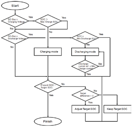
The system detects the state-of-charge (SOC) of the battery and charges and discharges it to reach a predefined level.
If necessary, a large power through the power sharing between the generator and the battery, to increase the output of the battery, by charging the electric power to the battery when idling, by maintaining a constant voltage of the DC grid, it maintains a stable output of the conversion device.
2.2 Comparison of Each Technology
Although progress has been made using the supercapacitor, its response time is poor owing to a slow charging rate compared with the Li battery, it is inefficient owing to self-discharging during the day, which should replace the limited repetition life (two years). In general, there are many difficulties due to the replacement of the entire system.
By lowering the speed of the diesel engine generator and fixed to 200 kW, by applying energy bank using a supercapacitor deal with instantaneous power level of 150 kW.
This system has a high energy efficiency and is suitable for operating RTGCs at short distances.
However, there are limitations owing to the short life cycle of the supercapacitor and the low volume energy density compared with the lithium-based system.
Instead of a supercapacitor as in existing methods, the proposed system uses a lithium-based energy bank.
For the hybrid system of the conventional lithium-based battery, a large-capacity battery should be used for ease of control, resulting in a high price. In this paper, by adding a duplex converter for optimum battery capacity, the proposed system has a price competitiveness.
For Li-based batteries, companies such as Samsung SDI and LG Chem. of Korea have the best technology in the world. In the future, the technological development and increase in the capacity of Li-based batteries are expected to provide excellent price competitiveness [4].
3. Proposed RTGC hybrid System
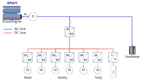
The average power consumption of current RTGCs is below 100 kW but typically operate with 350 kW diesel engine generators. Therefore, the generator does not operate at optimum efficiency, resulting in poor efficiency owing to a low load operation [5].
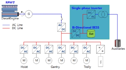
To solve this problem, this paper determines an optimum efficiency point to operate an engine generator and increase system efficiency by applying a duplex converter with buck–boost modes. Additionally, a battery that can be charged and discharged repeatedly is applied to the DC link.
When the RTGC is lifting and lowering a container, regenerative energy is generated when the braking is in progress.
This occurs when the regenerative energy of the conventional system consumes heat using a dynamic brake (DB).
However, in the proposed system, by storing electrical energy in both directions, the battery charging and discharging can improve system efficiency by greater than 20%. Even a long waiting time for loading and unloading containers that are not actually to supply electricity to the equipment, such as computers and communication equipment, has required the continuous operation of diesel generators.
In the proposed system, by adding a single inverter, if the RTGC is not restarted for a long time, the diesel engine is automatically stopped and power is supplied by the battery. Therefore, entire system efficiency can be increased by more than 50%. To realize the RTGC hybrid system, a stable operation is required despite decreasing the engine generator output, and the entire system must be mutually stable. In particular, controlling the DC link voltage of the inverter is very important. Because the proposed system applies a duplex battery charge and discharge system, the DC link voltage is controlled actively. Therefore, the aim is to control the DC link voltage ripple below 15%. In addition, it is very important to charge and discharge the battery efficiently to increase the efficiency of the overall system.
Based on the optimal design of the power converter technology to ensure the efficiency of the duplex buck-boost was 97%. Moreover, the efficiency of the entire battery system to the target for more than 87%. Figure 3 shows an algorithm to control the battery charging and discharging based on DC bus voltage to maintain the target SOC of the battery.
4. Performance verification of the proposed RTGC hybrid System
We established an RTGC system test bed at Korea Marine Equipment Research & Institute, Noksan, to verify the performance. The test results indicated that system stability was very excellent.
4.1 RTGC hybrid system test
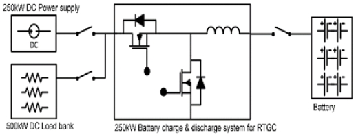
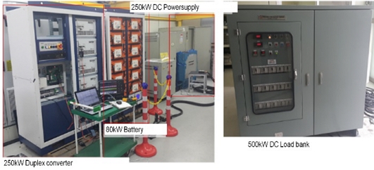
The system test was composed a 250 kW DC power supply and 500 kW-class DC load bank.
A 250 kW DC power supply was connected for the battery charge test. A 500 kW-class DC load bank was connected for the discharging test of the battery.
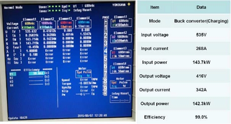
Stacking was conducted using a total of four parallel operations. The charging efficiency for charging and discharging the hybrid system was measured, as shown in Figure 6.
The input voltage was 535 V in the test performed with a 140 kW power output class. The stack charging efficiency was 99%.
The entire system efficiency was expected at 98.6% with a maximum power capacity of 0.5 kW.
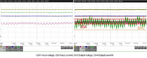
The ripple of the input and output was 30 A, which was 11% of the operating current. The output ripple was 6 A, which was 1.4% of the operating current. A large ripple appeared in the cycle owing to the input power ripple (approximately 16 ms cycle).
If the power supply changed to a battery, we expect the ripple to be reduced to 20 A.
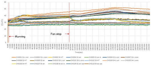
Figure 8 shows the saturation temperature of operation in the charging mode. Only the heat sink saturation temperature of the reactor was observed owing to the individual stack verification tests. Ambient temperature 50 ℃, It seems to be saturated at about 65 ℃. In conclusion, the hybrid system can operate without problems at an ambient temperature of 50 ℃.
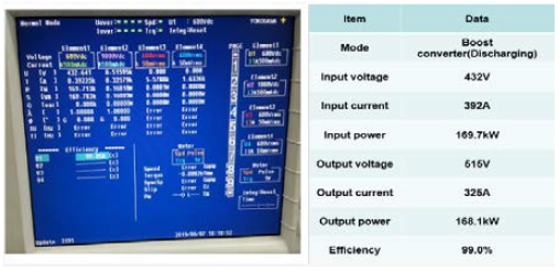
The discharging efficiency for charging and discharging the hybrid system was measured, as shown in Figure 9. The input voltage was 432 V in the test performed with a 169.7 kW power output class. The stack during discharging efficiency was 99%. We expected the entire system expected to be 98.6% with a maximum of power capacity of 0.5 kW.
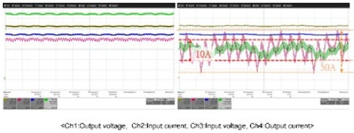
The ripple of input and output was 50 A, which was 12% of the operating current. The output ripple was 10 A, which was 3.1% of the operating current. A large ripple appeared in the cycle owing to the input power ripple (approximately 16 ms cycle).
If the power supply changed to a battery, we expect the ripple to be reduced to 20 A.
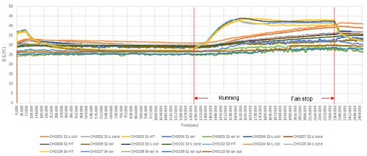
Figure 11 shows the saturation temperature of operation in the charging mode. Only the heat sink saturation temperature of the reactor was observed owing to individual stack verification testing. Ambient temperature 50 ℃ In seems to be saturated at about 70 ℃.
In conclusion, the hybrid system can operate without problems at an ambient temperature of 50 ℃
4.2 Battery operation test
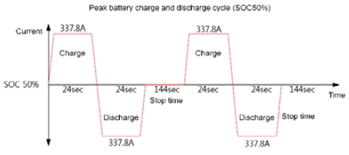
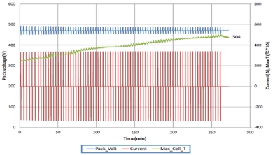
Figure 12 shows the battery charging and discharging cycle applied to the test similar to the shape of the operation pattern of the RTGC system.
A charging and discharging test of about 3C was conducted in 24-s intervals.
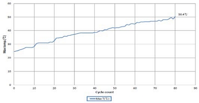
Figures 13 and 14 show about 80 cycles of the progression pattern shown in Figure 12. The temperature of the battery cell is shown to increase up to about 50 ℃.
If the charge–discharge operation is further proceeds, the temperature is likely to increase further.
However, in practice, a battery does not have this repetitive operation pattern. In addition, the operating conditions here were those of natural cooling.
Therefore, installing fans and an air-conditioning system would cause no problem.
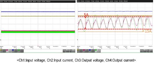
Figure 15 shows the battery and system inputs when the hybrid charge and discharge system used a battery.
The input current ripple was 15 A, which was 19.5% of the operating current. The output current ripple was 5 A, which was 5.5% of the operating current.
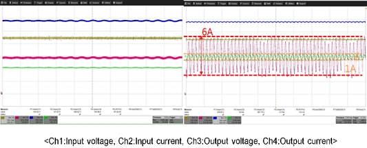
Figure 16 shows the battery 1C output and system output when the hybrid charge and discharge system used the battery
The input current ripple was 6 A, it is 4.2% compared to the operating current. The output current ripple was 1 A, which was 0.96% of the operating current.
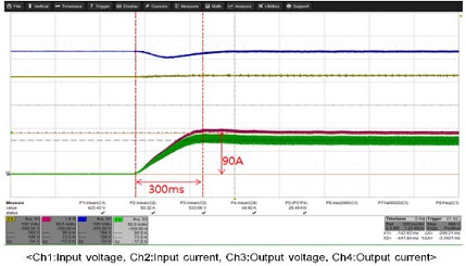
Figure 17 shows the response of the charging mode controller for this system. When the system operated in a 90 A step, the current response was 300 ms. However, this is expected to not be a problem because current rising time is second unit.
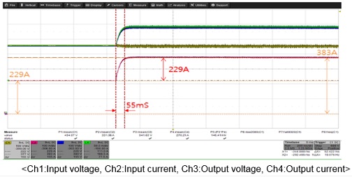
Figure 18 shows the response of discharging operation mode controller for this system. When the system operated in a 154 A step, the current response was 55 ms. However, this is expected to not be a problem because current rising time is second unit.
5. Demonstrative tests
5.1 System Configuration
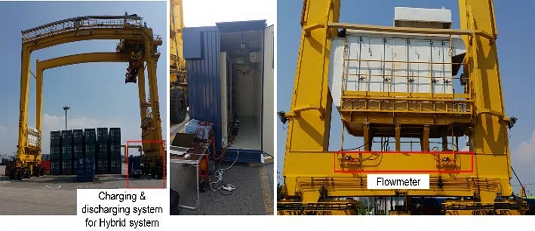
Figure 19 shows a photograph of the actual installation site at Incheon Sun-kwang Port.
The raising and lowering of a container was observed under an actual charge–discharge condition, wherein the fuel system was installed to measure the energy used.
5.2 Regenerative mode
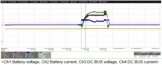
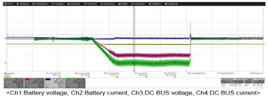
Figure 20 shows the waveform for charging the energy generated to the battery during the lowering operation of the RTGC.
5.3 Discharging mode
Figure 21 shows a waveform for discharging a part of the battery generated during the rising operation of the RTGC.
Here, an amount of about 90 kW of energy was discharged, showing that the discharge was constant during the operation.
5.4 Hybrid RTGC fuel consumption compared with a conventional system
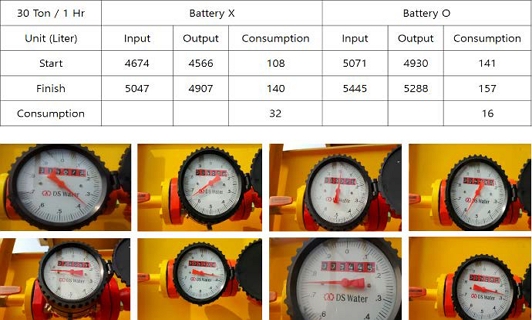
We conducted a test of the fuel consumption of a diesel engine generator to compare the proposed hybrid and conventional systems at Incheon Sun-kwang Port.
The fuel consumption of the conventional system was 32 L/h, whereas that of the proposed hybrid system was 16 L/h.
This indicated that fuel consumption savings of about 50% are possible.
5.5 Measurement of the Generator output and efficiency during charging and discharging
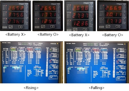
For the conventional RTGC system, the generator output was 276 and 12.3 kW in the rising and falling operations, respectively. For the hybrid RTGC system, the generator output was 124 kW and 17.1 kW in the rising and falling operations, respectively.
The converter efficiency of the crane was 98.6% and 99.1% in the rising and falling operations, respectively.
6. Conclusions
This paper examines the trends in the research and development of existing RTGC systems and proposes a new hybrid system for harbor cranes.
A test bed was built for the proposed system at the Noksan Headquarters of the Korea Marine Equipment Research Institute, the performance stability of the DC/DC converter researched and developed in the buck and boost modes was confirmed, and the stability of the system was verified with respect to the battery system. In addition, through directly applying the system to the RTGC at the Incheon Sun-Kwang Port, fuel consumption was reduced by 50%, and the efficiency of the DC/DC converter was approximately 99%, which was very excellent.
If price competitiveness is achieved along with the research and development of lithium-based batteries in the future, we expect that many hybrid RTGCs using the proposed system will be commercialized.
Acknowledgments
Supported by the Ministry of oceans and fisheries (MOF), Korea institute of marine science technology promotion (KIMST) through development project (20220324).
Author Contributions
Conceptualization, H. C. Kim; Methodology, H. C. Kim and J. S. Kim; Formal Analysis, H. M. Jeon; Investigation, H. M. Jeon; Resources, H. M. Jeon;; Data Curation H. C. Kim; Writing-Original Draft Preparation, H. C. Kim; Writing-Review & Editing, H. C. Kim and H. M. Jeon; Visualization, H. C. Kim; Supervision, H. C. Kim and J. S. Kim; Project Administration, J. S. Kim; Funding Acquisition, H. C. Kim and J. S. Kim.
References
- H. Hellendoorn, S. Mulder, and B. De Schutter, “Hybrid control of container cranes,” 18th IFAC World Congress, Milano, Italy, August 28 – September 2, 2011.
-
S. -M. Kim and S. -K. Sul, “Control of rubber tyred gantry crane with energy storage based on supercapacitor bank,” IEEE Transactions on power electronics, vol. 21, no. 5, pp 1420-1427, 2006.
[https://doi.org/10.1109/TPEL.2006.880260]

- S. Mulder, “Energy management strategy for a hybrid container crane,” Faculty of Mechanical, Maritime and Materials Engineering, Delft University of Technology, July 16, 2009.
- W. S. Kim, “Analysis of energy saving technology effects for container handling equipment,” Monthly Marine Fisheries magazine, no. 262, pp. 25-37, 2006.
- J. D. Kim, K. S. Jung, J. W. Lee, Y. H. Song, C. H. Jeong, and J. S. Choi, “Related low load operation of ship’s marine auxiliary engine,” Proceeding of the Korean Society of Marine Engineering, pp. 189-190, 2010 (in Korean).

