Design of a superconducting magnet system using a cryogenic magnetic coupler for contactless current charging
Copyright © The Korean Society of Marine Engineering
This is an Open Access article distributed under the terms of the Creative Commons Attribution Non-Commercial License (http://creativecommons.org/licenses/by-nc/3.0), which permits unrestricted non-commercial use, distribution, and reproduction in any medium, provided the original work is properly cited.
Abstract
General-purpose electromagnets are widely used to measure and analyze the magnetic properties of various materials. The performance of these electromagnets depends mainly on the magnitude and uniformity of the magnetic field. As the allowable current density of copper wires, which are generally used in these electromagnets, does not exceed 5 A/mm2 at room temperature, it is difficult to generate a high magnetic field, and water-cooling is required to mitigate the temperature rise at higher current densities. High-temperature superconductors (HTSs) have significantly higher current-carrying capacity than copper; thus, general-purpose electromagnets based on HTS coils can generate higher magnetic fields and are more compact than conventional electromagnets that use copper coils. However, given that the use of a superconducting joint is not feasible in an HTS coil, it should always be physically connected to an external power source at room temperature for current charging. This places a large thermal load on the cryogenic cooling system for the HTS coil, which may decrease the operating stability of the coil over time. This study proposes a general-purpose HTS electromagnet based on a contactless current-charging method. The proposed electromagnet is composed of a ferromagnetic iron yoke, HTS coils, cryogenic cooling system, and contactless charging system. The HTS electromagnet was designed and analyzed using finite element analysis coupled with electrical circuit analysis. The HTS electromagnet offers better field performance than a conventional general-purpose electromagnet even though it is only half the weight of the latter. We expect that the proposed HTS electromagnet can be applied in fields that require excellent magnetic field performance but also have size limitations.
Keywords:
Contactless charging method, Ferromagnetic iron yoke, Finite element analysis, General-purpose electromagnet HTS coil1. Introduction
General-purpose electromagnets are widely used to measure and analyze magnetic properties, such as magnetic hysteresis and magnetic susceptibility [1]-[4].
The performance of general-purpose electromagnets depends mainly on the magnitude and uniformity of the magnetic field in the sample space. Generally, copper coils are used for generating a magnetic field in conventional electromagnets. However, as the allowable current density of copper wires does not exceed 5 A/mm2 at room temperature (RT), conventional electromagnets are not feasible for generating a high magnetic field in a limited volume.
Superconductors are known to have very high current-carrying capacities compared to normal conductors, such as copper and aluminum. In particular, high-temperature superconductors (HTSs) have a very high current-carrying capacity compared to normal conductors, and they are thus widely studied for application in ultra-high field magnets for physical property measurements [5]-[7]. HTS-based electromagnet systems are expected to generate higher magnetic fields in a compact size compared to conventional electromagnets that use copper coils. Therefore, several studies have attempted to apply HTS coils to general-purpose electromagnets [7]-[9]. In these studies, the HTS coil is current-charged in a power-driven mode, where the HTS coil is physically connected to an external power supply at RT. This places a large thermal load on the cryogenic cooling system for the HTS coil, which can thereby decrease the operating stability of the coil. As superconducting joints cannot be realized using the HTS tape, HTS coils, in contrast to low-temperature superconductor coils, cannot be operated in constant current mode.
Furthermore, the HTS coil must be physically connected to the external power supply even after its operating current attains the target current.
This issue has been addressed by investigating techniques, such as flux pumps and joint-less HTS coils [10]-[11]. However, these are limited to small-capacity magnets; thus, a technique that can be applied universally needs to be developed.
The present study proposes a new type of general-purpose HTS electromagnet based on a contactless current-charging method using a magnetic coupler. The proposed model is composed of HTS coils, a ferromagnetic iron yoke, a cryogenic cooling system, and a magnetic coupler. The iron yoke has an H-frame configuration and uses cobalt iron, which has superior magnetic properties. The HTS coils are designed using Ic–B data for a commercial 2G HTS tape. To do this, the dependency of the critical current of the HTS tape on an external magnetic field is measured. A finite element analysis model coupled with an electrical circuit model is developed to evaluate the current-charging characteristics. The results demonstrate the feasibility of the proposed general-purpose HTS electromagnet.
2. Configuration
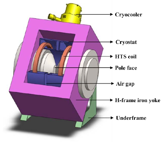
Figure 1 shows the proposed general-purpose HTS electromagnet. It consists mainly of four parts: a pair of HTS coils, cryogenic cooling system, H-frame iron yoke, and current charging system. Although the shape of the H-frame iron yoke is identical to that of a conventional electromagnet, the diameter of the excitation coil can be reduced because of the use of the HTS coils, meaning that the size of the iron yoke can be reduced. Each HTS coil consists of double-pancake coils, and the pole is surrounded by the HTS coils. The proposed configuration does not require a refrigerant and is compact.
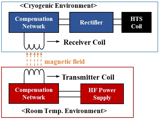
In the proposed model, contactless charging method is used instead of the conventional power-driven mode to charge current to the HTS coil. A schematic of a contactless current charging system using a magnetic coupler is shown in Figure 2. In the charging system, a compensation network is necessary to reduce the leakage inductance because the transmitter (TX) coil and receiver (RX) coil are loosely coupled. In this study, a series–series compensation network was used for the proposed electromagnet system, as this network facilitates power transfers even with a large air gap.
3. HTS electromagnet and magnetic coupler design
This study aims to propose an HTS electromagnet model that is more compact than a conventional electromagnet and has equal or better performance. Therefore, we proceed with the initial design based on model 3474 of GMW Associates, a representative general-purpose electromagnet manufacturing company. The model 3474 electromagnet has the following specifications: a pole diameter of 250 mm, H-frame iron yoke dimensions of 920 mm width × 636 mm thickness × 864 mm height, a weight of 1,800 kg, and a maximum magnetic field density of 3.5 T with a 10 mm gap distance and 25 mm pole face. The pole diameter of the proposed HTS electromagnet equals that of the model 3474 electromagnet but has smaller coil and iron yoke because of the use of the HTS coil.
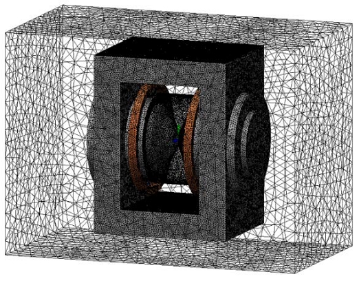
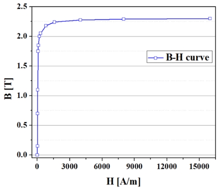
To design the HTS electromagnet, an electromagnetic analysis coupled with an electrical circuit analysis was performed using commercial finite element modeling software and an electromagnetic analysis tool for solving Maxwell equations to determine the magnetic field within the model. Figure 3 shows the 3D model that includes the HTS coils, H-frame iron yoke, the pair of poles, and the air domain. The cryocooler and cryostat for HTS coils, and the underframe were ignored for simplification of the model. In the case of air domain, a sub-air domain was built to analyze field distribution more precisely in a region between pole faces. For an H-frame iron yoke and poles, a ferromagnetic material with the magnetization curve shown in Figure 4 was used.
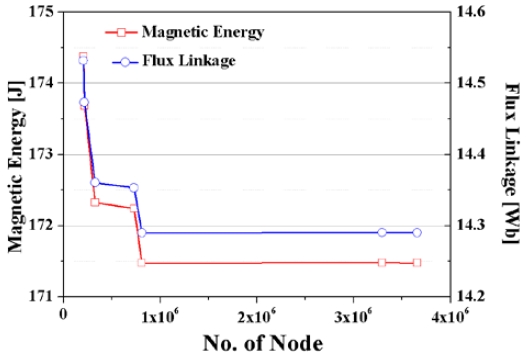
In addition, mesh convergence tests were performed to enhance the reliability of this simulation model, and the results are shown in Figure 3. The magnetic energy and flux linkage in the coil according to the number of nodes in the analysis model were simulated, and these values converged to 171.48 J and 14.3 Wb, respectively, at the number of nodes greater than 810,000.
The simulation was iterated while maintaining the pole diameter and changing the dimensions of the iron yoke and the magnetomotive force (MMF) of the HTS coil. Based on the simulation results, the height, width, and thickness of the iron yoke were designed to be 670, 750, and 400 mm, respectively, and the required MMF of the HTS coil was found to be 9.6 kA·t. When the HTS coil is excited with the maximum MMF, the magnetic field density at a gap distance of 20 mm and a pole face of 20 mm exceeds 3.8 T. Specifications of the proposed electromagnet model and commercial model 3474 electromagnet are compared in Table 1.

Comparison of specifications between the proposed electromagnet and commercial model 3474 electromagnet
Compared to the model 3474 electromagnet, the proposed electromagnet model has a 40% smaller overall volume and 20% higher field density at a 20 mm gap distance. In addition, the target specification of the field uniformity was determined so that the value could be further improved over the specification presented in model 3474. Based on the designed specifications of the electromagnet, an HTS coil capable of generating a target MMF was designed.
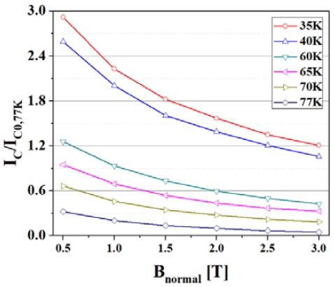
To design the HTS coils, the critical current degradation characteristics must be parameterized with the external magnetic fields and operating temperature. Figure 6 shows the measured dependency of the magnetic field on the critical current of the 2G HTS wire. The test equipment shown in Figure 7 was used for this experiment. The test equipment is a cryogen-free superconducting property measurement system (SPMS) which was developed by the Korea Electrotechnology Research Institute in 2011 [12]-[13]. The system consists of a racetrack-type background magnet, HTS current lead, and cryocooler. The background magnet has a split-pair winding configuration, and RT bore of the magnet has dimensions of 38 mm (length) × 134 mm (width) × 360 mm (depth). In addition, the field uniformity of SPMS is lower than 1% within the virtual sample region of 15 mm (width) × 100 mm(depth). The specifications of the test equipment are summarized in Table 2 [12].
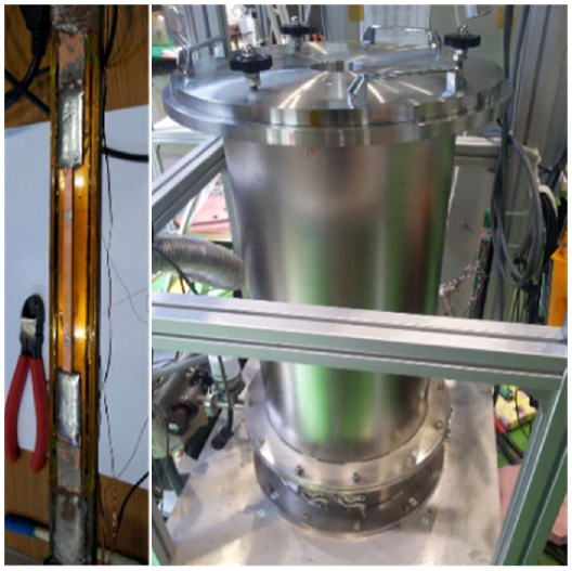
System used for measuring the critical current of the HTS tape according to the operating temperature and external magnetic field
After installing the HTS tape in the sample holder of the SPMS, the sample holder was inserted into the RT bore of the SPMS. Using a cryocooler connected to the sample holder, HTS tape was cooled to the target temperature. After that, the critical current of the HTS tape was measured using the 4-point method while gradually increasing the current flowing through the HTS tape using the power supply. In this experiment, the magnitude of the external magnetic field and the cooling temperature of the HTS tape were used as variables, and the critical current was measured while increasing the external magnetic field from 0.5 to 3 T at the field orientation (θ) of 90°. The Ic–B curve data at 40 K in Figure 6 was used to determine the maximum operating current of the HTS coil [14]-[15]. The specifications of the designed HTS coil are shown in Table 3.
In this study, a TX coil and an RX coil for contactless current charging of the HTS coil were designed. Considering the overall size of the HTS electromagnet system, planar circular-type geometries of the TX coil and RX coil were selected. The two coils were designed based on the coil geometry parameters and inductance. The fundamental geometric specifications of the two coils were roughly designed to enhance the coupling coefficient, and then the two coils were designed in more detail via a finite element analysis.
The compensation capacitances at the transmitter side and receiver side in the series–series compensation topology were calculated using Equation (1) [16]-[17].
| (1) |
where f0 is the operating frequency, which was set to 10 kHz in this study. The gap distance between the TX and RX coils was determined to be 30 mm considering the multi-layer insulation, which is used for radiation shielding of the cryogenic system. Table 4 shows the specifications of the magnetic coupler, including the TX coil, RX coil, and compensation network.
The contactless current-charging method used in the proposed electromagnet model has lower power transfer efficiency than the conventional power-driven method. However, the purpose of the proposed method is to improve the thermal stability of the HTS magnet system, which may be achieved by reducing the thermal load caused by the current lead. Therefore, in this study, the thermal load of the HTS magnet system under the power-driven method was compared to that under the contactless currentcharging method. The thermal loads of the HTS magnet system were calculated using Equations (2)-(4) [18]-[19].
| (2) |
| (3) |
| (4) |
where, QCL and QK are the conduction thermal loads by a pair of current leads and the leading-in tubes for the signal lines, respectively; QR is the thermal load by the radiation heat transfer from the vessel wall. The thermal load calculated from the equations was 4.87 W for the power-driven method and 1.94 W for contactless-charging method. Therefore, it is expected that the thermal load of the HTS magnet system can be reduced by more than 60% using the proposed model. Although the eddy-current loss due to leakage flux between Tx and Rx coils was not considered in this calculation, the use of a non-metallic material, such as glass fiber reinforced polymer for a part of the cryostat between the Tx and Rx coils is expected to reduce the effect.
4. Results and discussion
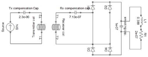
In this study, we analyzed the charging characteristics of the HTS coil by the contactless current-charging method. The excitation current to the HTS coil was supplied through a full-wave rectifier and a smoothing capacitor. Figure 8 shows the circuit diagram, including the full-wave rectifier and compensation network. Figure 9 shows the simulation results for the charging current in the transmitter current condition of 30 A and 10 kHz.
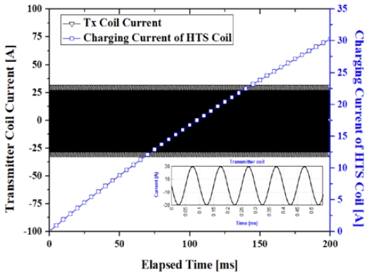
Simulation results for the current charging characteristics of the HTS coil by contactless current-charging method
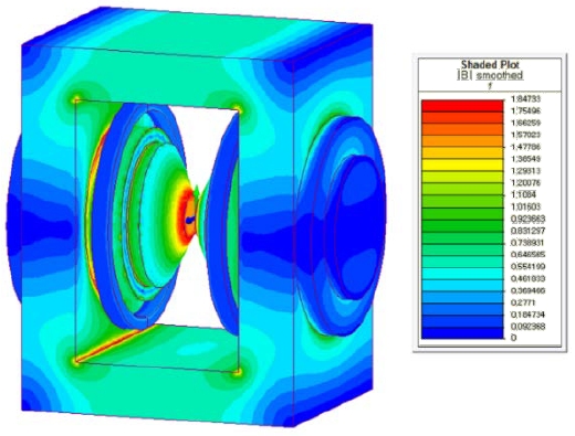
The current in the HTS coil was charged with an operating current of 30 A for approximately 200 ms, which is much faster than the normal charging speed of an HTS coil. Therefore, to stably charge the HTS coil, the current must be gradually increased on the transmitter side. After the current-charging of the HTS coil, the magnetic field distribution in the sample space was analyzed. Figure 10 shows the simulation results for the magnetic field distribution in the HTS electromagnet. The results indicate that the H-frame iron yoke and pair of poles play a significant role in guiding and focusing the magnetic field. Given that the H-frame iron yoke and poles consist of a ferromagnetic material with very high magnetic permeability, the magnetic field can flow across both pole tips through the air gap.
Figures 11(a) and (b) demonstrate that the HTS electromagnet provides spatial field uniformity of <2% over a 10 mm diameter of the spherical volume (DSV). The spatial field can be improved by increasing the area of the pole face. However, this weakens the concentration of the magnetic field and the air gap field density [18]. Compared to the conventional general-purpose electromagnet, the proposed HTS electromagnet model can generate a relatively high magnetic field while maintaining excellent spatial field uniformity.
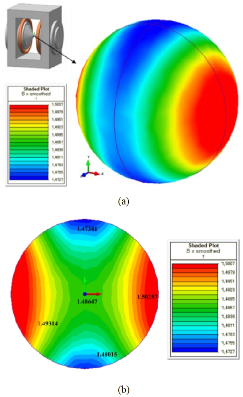
Magnetic field distribution in the 10 mm DSV of the air gap at a 20 mm gap distance, with 25 mm pole face, and at 8 kA·t: (a) 3D view, and (b) 2D view of the center
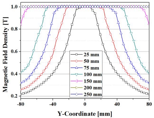
Figure 12 shows the distribution of the magnetic field in the y-axis direction. The graphs plot the magnetic field density from y = -80 mm to y = 80 mm in steps of 0.16 mm. Cut lines of the magnetic field at different positions are given, showing relatively good field homogeneity at r < 10 mm. The inhomogeneity of the magnetic field can be reduced by increasing the diameter of the pole face. Figure 13 shows the air gap field densities with the MMF and diameter of the pole face. The magnetic field densities in the air gap increase linearly to 2.0 T as the operating current increases. However, the magnetic field density in the oversaturated region is significantly limited by the coil current. This occurs because the leakage flux in the saturation region increases as the MMF stemming from the coil current increases. In addition, the maximum magnetic field of the HTS electromagnet with a 25 mm pole face and 5 mm gap distance is limited to 4.35 T or less based on the critical current of the HTS coil.
5. Conclusion
In this study, a general-purpose electromagnet utilizing a ferromagnetic iron yoke and HTS coils charged using a contactless charging method was designed, and the current charging characteristics of the HTS coil and the magnetic field performance were assessed using finite element analysis coupled with electrical circuit analysis. To design the HTS coil, the dependency of critical current on the external magnetic field of 2G HTS tape was experimentally evaluated. Based on the simulation results, we confirmed that the HTS coil in the proposed HTS electromagnet model can be excited using the contactless charging method. In addition, the designed HTS electromagnet provided variable magnetic fields of 0–3 T at a 20 mm gap distance and 100 mm pole face with field homogeneity of better than 2% within a 10 mm DSV. Compared to the conventional electromagnet, the proposed model is more compact and has higher field performance, implying greater suitability in situations affected by size limitations. Thus, this design is expected to be used in nuclear magnetic resonance equipment, superconducting synchronous motors for electric propulsion, and superconducting synchronous generators for offshore wind power as it can reduce the thermal load caused by current conductors. However, this study only considers simulation results, whereas the actual model has not yet been fabricated and assessed. Therefore, in future research, we plan to verify the proposed method through actual model fabrication and testing.
Acknowledgments
This work was supported by the Korea Maritime and Ocean University Research Fund in 2021, and a grant from the National Research Foundation of Korea (NRF) funded by the Korean government (MSIT) (No. 2021R1F1A1052767).
Author Contributions
Conceptualization, Y. J. Hwang and J. E. Park; Methodology, Y. J. Hwang; Software, Y. J. Hwang; Validation, Y. J. Hwang and J. E. Park; Formal Analysis, Y. J. Hwang; Investigation, Y. J. Hwang; Resources, Y. J. Hwang; Data Curation, Y. J. Hwang; Writing—Original Draft Preparation, Y. J. Hwang; Writing—Review & Editing, J. E. Park; Visualization, Y. J. Hwang; Supervision, J. E. Park; Project Administration, Y. J. Hwang; Funding Acquisition, Y. J. Hwang.
References
-
Y. J. Hwang, J. Y. Jang, S. -Y. Park and Y. S. Choi, “Feasibility study of a multipole electromagnet using a parallel iron-core structure,” in IEEE Transactions on Applied Superconductivity, vol. 28, no. 3, pp. 1-5, 2018.
[https://doi.org/10.1109/TASC.2018.2800715]

-
E. Arenholz, et al., “Design and performance of an eight-pole resistive magnet for soft x-ray magnetic dichroism measurements,” Review of Scientific Instruments, vol. 76, no. 8, p. 083908, 2005.
[https://doi.org/10.1063/1.2008027]

-
N. Hosseini, S. Khiabani, F. Sarreshtedari, and M. Fardmanesh, “Optimized design and implementation of low-cost, sensitive and versatile Vibrating Sample Magnetometer,” 20th Iranian Conference on Electrical Engineering (ICEE2012), pp. 202-205, 2012.
[https://doi.org/10.1109/IranianCEE.2012.6292353]

-
S. Boukari, et al., “Four pole electromagnet for in situ magneto-optical measurements,” Vacuum, vol. 52, no. 3, pp. 327-331, 1999.
[https://doi.org/10.1016/S0042-207X(98)00313-3]

-
C. Y. Lee, et al., “Design, fabrication, and operating test of the prototype HTS electromagnet for EMS-based maglev,” in IEEE Transactions on Applied Superconductivity, vol. 22, no. 3, p. 3600504, 2012.
[https://doi.org/10.1109/TASC.2012.2186778]

-
Y. J. Hwang, et al., “A study on the shape of iron-core for a hybrid electro-magnetic suspension system,” in IEEE Transactions on Applied Superconductivity, vol. 22, no. 3, p. 3600204, 2012.
[https://doi.org/10.1109/TASC.2011.2180280]

-
D. M. Pooke, et al., “A versatile laboratory electromagnet with HTS coils,” IEEE Transactions on Applied Superconductivity, vol. 14, no. 2, pp. 1202-1205, 2004.
[https://doi.org/10.1109/TASC.2004.830528]

-
J. Y. Jang, et al., “Development of a cryogen-free compact 3 T superconducting magnet for an electromagnetic property measurement system,” Applied Sciences, vol. 11, no. 7, p. 3074, 2021.
[https://doi.org/10.3390/app11073074]

-
S. You, et al., “Numerical simulation of magnetic field for compact electromagnet consisting of REBCO coils and iron yoke,” Superconductor Science and Technology, vol. 31, p. 075007, 2018.
[https://doi.org/10.1088/1361-6668/aac614]

-
S. Lee, et al., “Persistent current mode operation of a 2G HTS coil with a flux pump,” IEEE Transactions on Applied Superconductivity, vol. 26, no. 4, pp. 1-4, 2016.
[https://doi.org/10.1109/TASC.2016.2524519]

-
M. Yoon, et al., “Field Mapping of the Jointless HTS solenoid magnet in a persistent current mode operation,” IEEE Transactions on Applied Superconductivity, vol. 29, no. 5, pp. 1-4, 2019.
[https://doi.org/10.1109/TASC.2019.2898516]

-
M. H. Sohn, et al., “Fabrication and test results of HTS magnet for a superconducting property measurement system,” Physica C: Superconductivity and its Applications, vol. 471, no. 21-22, pp. 1449-1453, 2011.
[https://doi.org/10.1016/j.physc.2011.05.214]

-
M. H. Sohn, et al., “Design and manufacturing of a conduction-cooled sample holder for a superconducting property measurement system,” IEEE Transactions on Applied Superconductivity, vol. 25, no. 3, pp. 1-4, 2015.
[https://doi.org/10.1109/TASC.2014.2384533]

-
H. C. Jo, et al., “Characteristics comparison for the various winding methods of HTS magnets,” IEEE Transactions on Applied Superconductivity, vol. 22, no. 3, p. 4902907, 2012.
[https://doi.org/10.1109/TASC.2012.2186549]

-
M. Kang, et al., “Current estimation of an HTS BSCCO magnet having multiple power sources based on the field dependent E-J relation,” IEEE Transactions on Applied Superconductivity, vol. 19, no. 3, pp. 1257-1261, 2009.
[https://doi.org/10.1109/TASC.2009.2018042]

-
A. Khaligh, et. al., “Comprehensive topological analysis of conductive and inductive charging solutions for plug-in electric vehicles,” IEEE Transactions on Vehicular Technology, vol. 61, no. 8, pp. 3475-3489, 2012.
[https://doi.org/10.1109/TVT.2012.2213104]

-
W. Zhang, et al., “Analysis and comparison of secondary series- and parallel-compensated inductive power transfer systems operating for optimal efficiency and load-independent voltage-transfer ratio,” IEEE Transactions on Power Electronics, vol. 29, no. 6, pp. 2979-2990, 2014.
[https://doi.org/10.1109/TPEL.2013.2273364]

- F. P. Incropera, Fundamentals of Heat and Mass Transfer, John Wiley & Sons, New York, NY, USA, 1996.
-
J. M. Kim, et al., “A new outer-rotor hybrid excited fluxswitching machine employing the HTS homopolar topology,” Energies, vol. 12, no. 4, p. 2654, 2019.
[https://doi.org/10.3390/en12142654]


