Dynamic simulation of Methane Number variations in LNG fueled vessels with periodic bunkering operations
Copyright © The Korean Society of Marine Engineering
This is an Open Access article distributed under the terms of the Creative Commons Attribution Non-Commercial License (http://creativecommons.org/licenses/by-nc/3.0), which permits unrestricted non-commercial use, distribution, and reproduction in any medium, provided the original work is properly cited.
Abstract
The effect of periodic bunkering operations on methane number (MN) and Wobbe index (WI) variations in the fuel gas supply system of liquefied natural gas (LNG)-fueled vessels has been numerically investigated by considering the changes in the representative gas composition and separator temperature. As a result, it was possible to manage the MN to avoid the occurrence of abnormal operation for the commercial engine requirement of MN ≥ 65 when the separator temperature was set to −50 ℃ despite the rich gas composition for bunkering having MN < 65. All the simulation conditions indicated that the main and generator engines were operated with WI < 56, while the boiler was operated in a wide range of MN ≒ 37–85 and WI ≒ 53–80.
Keywords:
Bunkering, Methane number (MN), Wobbe Index (WI), Liquefied Natural Gas (LNG), Fuel Gas Supply System (FGSS), LNG fueled vessel1. Introduction
In recent years, liquefied natural gas (LNG)-fueled ships have gained international attention as a potential eco-friendly propulsion system to reduce exhaust gas emissions from ships, which is regulated by the Marine Environment Protection Committee (MEPC) in the International Maritime Organization (IMO). The types of dual-fuel engines classified into a high-pressure Diesel cycle and low-pressure Otto cycle are important in the design of fuel gas supply system (FGSS) for LNG [1].
The Diesel cycle engine (e.g., MAN B&W’s MEGI) has an autoignition method with a high compression ratio and high thermal efficiency but requires a high-pressure gas fuel supply above approximately 300 bar and a nitrogen oxide (NOx) emission reduction device such as selective catalyst reduction (SCR) [2]. In contrast, the Otto cycle engine (e.g., Winterthur Gas & Diesel’s X-DF) has a low operating pressure of approximately16 bar and satisfies the exhaust gas regulation standards without an after-treatment device, so it is preferred in the market in terms of economic feasibility [3]. However, since the compression ratio for the Otto cycle engine is limited by the occurrence of knocking, special attention is required in fuel quality control.
As a fundamental study, the critical compression ratio implying the occurrence of light knock in a Cooperative Fuel Research (CFR) F-2 engine was investigated as a function of methane number (MN) of alternative gaseous fuels [4]. Although recent research on engine combustion simulation has suggested that the appropriate minimum methane number is 70 [5], most engine manufacturers recommend MN ≥ 80 to achieve fuel economy for high power and low emissions [6]. The commercial Otto cycle engine (XDF) adopts active combustion control for the low MN conditions, resulting in MN ≥ 65 [7].
For LNG fueled ships with the Otto cycle engine, the steady and unsteady process simulations for the fuel gas supply systems were conducted for global oceangoing LNG carriers and propulsion vessels considering different MNs according to relevant sources [8][9]. The process control strategies were also studied to deal with MN fluctuations for different LNG compositions [10]. In this paper, we report the effect of periodic bunkering operations on methane number (MN) variations in LNG propulsion systems.
2. Simulation model
The LNG fueled vessel was modeled with a storage tank volume of 3,600 m3 with a boil-off rate (BOR) of 0.32%/day. A main engine and three generators of the low-pressure Otto cycle engine consumed LNG along with a gas boiler as summarized in Table 1.
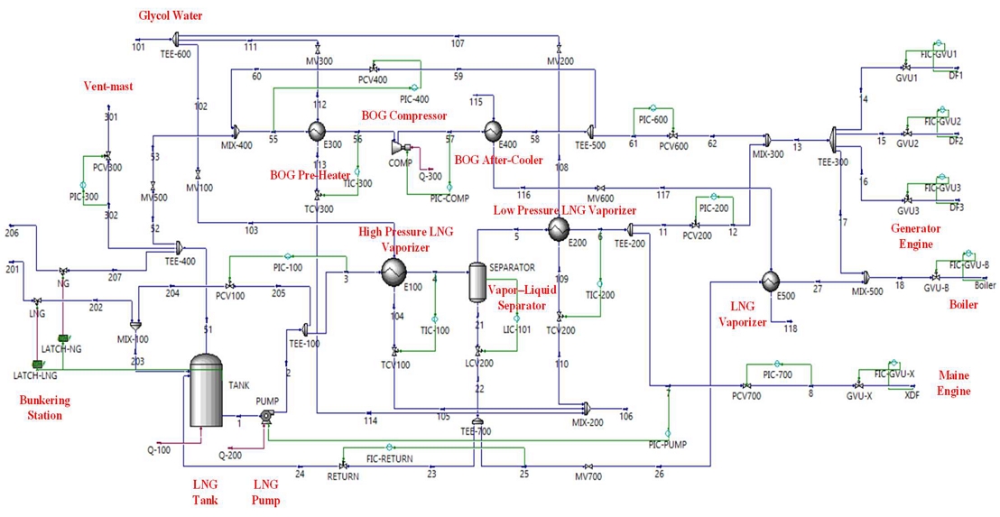
Figure 1 shows a process flow diagram for an LNG FGSS comprising vaporization, boil-off gas (BOG) treatment, vent, and bunkering equipment, which was modeled with ASPEN HYSYS software. The details of the operating conditions for each state are listed in Table 2. Here, the mass flow in the BOG (NG) pipeline occurred several hours after bunkering. Further, GW stands for glycol water. Table 3 shows representative gas compositions used in the simulation cases. The representative operating conditions in Table 2 were simulated with the initial gas composition with respect to the separator temperature of −50 ℃. MN was calculated as a function of the hydrogen/carbon ratio, x, as shown in Equation (1) [11].
| (1) |
where MON is the motor octane number fitted by the third-order polynomial.
In addition, the Wobbe index (WI) or Wobbe number was calculated with the volumetric higher heating value, HHVv, and relative density, RD, from Equation (2) [12].
| (2) |
3. Results and discussion
3.1 MN variations for the initial gas composition
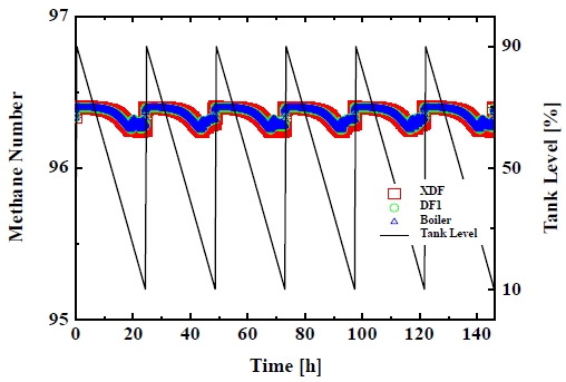
Figure 2 shows the MNs as a function of time, which were calculated at each state of XDF as an inlet of the main engine, DF1 as an inlet among the three auxiliary engine generators, and the Boiler. After the periodic bunkering of approximately 0.5 h from 10% to 90% of the liquid level of the LNG storage tank, the MNs decreased gradually from 96.39 to 96.25 during the voyage of approximately 27 h while steadily consuming the liquid level from 90% to 10%. Then, the MNs were recovered to those corresponding to the bunkering of the initial gas composition. In all processes, the MN deviations of each state were negligible with each other.
3.2 Power variations for abnormal operation
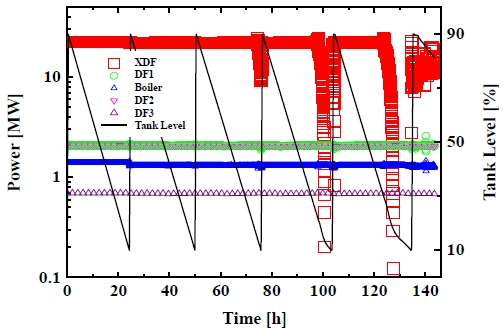
After one period, which is the single voyage after the first bunkering, the initial gas composition was switched to the typical gas composition for the second bunkering. And the separator temperature was set at the same time by lowering it from −50 ℃ to −80 ℃. The results are shown in Figure 3. During the second bunkering, the output power of the boiler was slightly reduced because of the fuel supply of the higher volume ratio of heavier hydrocarbons, but the power deviations in the three generators were negligible. However, the power for the main engine (XDF) dropped by approximately 10 MW at the end of the voyage before the fourth bunkering. It means that the amount of the relatively light methane fuel supplied to the main engine was inadequate to maintain the 85% load because the heavier carbon fuel accumulated in the LNG tank. In the case of continuous repetition, the output power rapidly dropped to the 0.1 MW level and the sailing time increased. It was recovered by the next bunkering, but the output control of the power supply completely deviated from the normal operation after the sixth bunkering.
3.3 Methane number variations with time
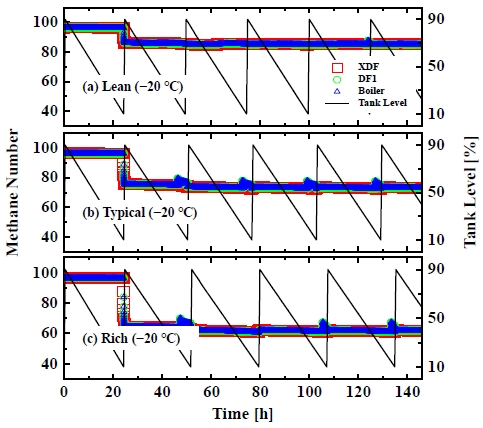
At the separator temperature of −80 ℃, the gas composition was changed to (a) lean, (b) typical, and (c) rich as shown in Figure 4. For the lean case, (a), the MNs were kept at approximately 89 for the main and generator engines and approximately 42 for the boiler, respectively. For the typical case, (b), the MN broke down from approximately 85 to 75, resulting in the abnormal operation after the sixth bunkering. For the rich case, (c), the abnormal operation appeared after the third bunkering. This indicates that the richer gas composition, the more accelerated the aging phenomenon with the heavier fuel accumulation in the LNG tank.
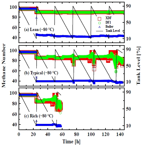
Methane number variations with time at the separator temperature of −80 ℃ for (a) lean, (b) typical, and (c) rich gas compositions
In Figure 5, the MNs for the three gas compositions were recorded with time when the separator temperature was heated up to −50 ℃ for the second bunkering. The lean, (a), and typical, (b), cases were normally operated with the MNs above approximately 73 for the engines and approximately 60 for the boiler.
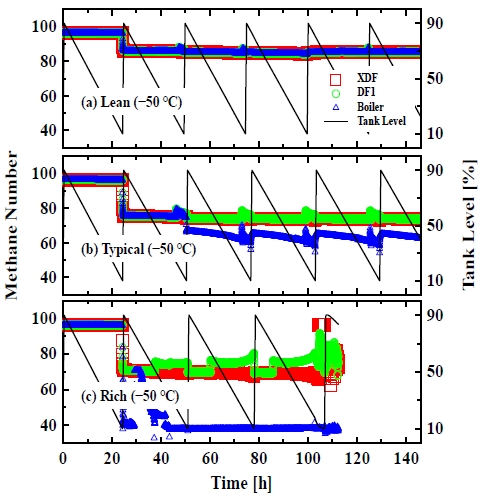
Methane number variations with time at the separator temperature of −50 ℃ for (a) lean, (b) typical, and (c) rich gas compositions
For the rich case, (c), although the rich gas composition has MN < 65, the MN management was in compliance with the commercial engine requirement of MN ≥ 65. However, the abnormal operation appeared after the fifth bunkering. Here the boiler was operated with the MN above approximately 37.
When the separator temperature was set to −20 ℃, all MNs in all devices maintained their own values for the three gas compositions, without experiencing abnormal operation as shown in Figure 6. However, the rich case, (c), was operated with MN < 65.
3.4 Methane number vs Wobbe index
WI is one of the best indicators of the interchangeability of gaseous fuel mixtures. Natural gas and LPG have typical ranges of WI values of 48–51 and 72–87, respectively [13]. In this regard, the MN over time as a result of the dynamic simulation was replotted by WI as shown in Figures 7–9, as a result of dynamic simulations for the separator temperatures of −20 ℃, −35 ℃, −50 ℃, and −80 ℃.
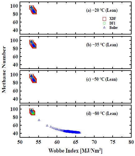
Methane number versus Wobbe index at the separator temperatures of (a) −20 ℃, (b) −35 ℃, (c) −50 ℃, and (d) −80 ℃ for the lean gas composition
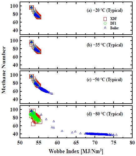
Methane number versus Wobbe index at the separator temperatures of (a) −20 ℃, (b) −35 ℃, (c) −50 ℃, and (d) −80 ℃ for the typical gas composition
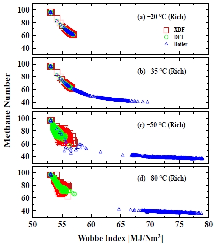
Methane number versus Wobbe index at the separator temperatures of (a) −20 ℃, (b) −35 ℃, (c) −50 ℃, and (d) −80 ℃ for the rich gas composition
Figures 7-9 for the lean, typical, and rich cases showed a general trend in which the MN was inversely proportional to the WI. The lower the separator temperature and the richer the gas composition, the greater the WI range, which clearly appears to be around 65–80 for the boiler inlet in Figure 9(c,d).
6. Conclusion
In this study, dynamic simulations were conducted to understand the effect of periodic bunkering operations on the MN variations in LNG propulsion systems. The time-dependent MN and WI for the engine and boiler devices were derived and compared with the changes in the representative gas compositions and separator temperatures. The main findings of this study are summarized as follows:
- ① Although the rich gas composition for bunkering has MN < 65, the requirement of a commercial engine with MN ≥ 65 could be satisfied by setting the separator temperature to −50 ℃.
- ② In the rich and −50 ℃ case, the occurrence of abnormal operation after the fifth bunkering implied that continuous bunkering with the rich gas composition should be discouraged.
- ③ All the simulation conditions indicated that the main and generator engines were operated with WI < 56. However, because the boiler was operated in a wide range of MN ≒ 37–85 and WI ≒ 53–80, the gas boiler should be designed to cover both natural gas and LPG fuels sufficiently.
Acknowledgments
This research was supported by Korea Institute of Marine Science & Technology Promotion (KIMST) funded by the Ministry of Ocean and Fisheries (20220603), Basic Science Research Program through the National Research Foundation of Korea (NRF) funded by the Ministry of Education (2022R1I1A3063360), Regional Innovation Strategy (RIS) through the National Research Foundation of Korea (NRF) funded by the Ministry of Education (MOE) (2021RIS-004), and University Innovation Support (UIS) project funded by the Ministry of Education.
Author Contributions
Conceptualization, B. C. Choi; methodology, J. I. Lee; Software, J. I. Lee; Formal Analysis, B. C. Choi; Investigation, J. I. Lee and B. C. Choi; Resources, J. I. Lee and B. C. Choi; Data curation, J. I. Lee and B. C. Choi; Writing-Original Draft Preparation, B. C. Choi; Writing-Review & Editing, J. I. Lee and B. C. Choi; Visualization, B. C. Choi; Supervision, B. C. Choi; Project Administration, B. C. Choi; Funding Acquisition, B. C. Choi.
References
-
M. Chorowski, P. Duda, J. Polinski, and J. Skrzypacz, “LNG systems for natural gas propelled ships,” IOP Conference Series: Materials Science and Engineering, vol. 101, p. 012089, 2015.
[https://doi.org/10.1088/1757-899X/101/1/012089]

- L. R. Juliussen, M. J. Kryger, and A. Andeasen, “MAN B&W ME-GI engines. Recent research and results,” Proceedings of the International Symposium on Marine Engineering (ISME), 585, 2011.
- M. Ott, I. Nylund, R. Alder, T. Hirose, Y. Umemoto, and T. Yamada, “The 2-stroke low-pressure dual-fuel technology: from concept to reality,” CIMAC Congress, vol. 233, 2016.
-
M. Malenshek and D. B. Olsen, “Methane number testing of alternative gaseous fuels,” Fuel, vol. 88, no. 4, pp. 650-656, 2009.
[https://doi.org/10.1016/j.fuel.2008.08.020]

-
J. Liu and C. E. Dumitrescu, “Numerical investigation of methane number and wobbe index effects in lean-burn natural gas spark-ignition combustion,” Energy & Fuels, vol. 33, no. 5, pp. 4564-4574, 2019.
[https://doi.org/10.1021/acs.energyfuels.8b04463]

-
S. Kuczynski, M. Laciak, A. Szurlej, and T. Wlodk, “Impact of liquiefied natural gas composition changes on methane number as a fuel quality requirement,” Energies, vol. 13, no. 19, p. 5060, 2020.
[https://doi.org/10.3390/en13195060]

- WIN GD, Low-pressure X-DF engines FAQ, 2020.
- Y. S. Yoo, A Study on the Process Analysis and the Fuel Gas Heating Temperature Change for the Improvement of Dual Fuel Engine Fuel Gas Methane Number of LNGC, Master's Thesis, Graduate School, Korea Maritime and Ocean University, 2018 (in Korean).
-
Y. Shao, S. Yun, and H. Kang, “Dynamic simulation of fuel tank ageing for LNG-fueled ship apparatus in an X-DF Otto cycle engine,” Energy Science & Engineering, vol. 7, no. 6, pp. 3005-3019, 2019.
[https://doi.org/10.1002/ese3.475]

-
S. -K. Hwang and B.-G Jung, “Methane number control of fuel gas supply system using combined cascade/feed-forward control,” Journal of Marine Science and Engineering, vol. 8, no. 5, p. 307, 2020.
[https://doi.org/10.3390/jmse8050307]

-
J. Kubesh, S. R. King, and W. E. Liss, Effect of Gas Composition on Octane Number of Natural Gas Fuels, Technical Paper 922359, SAE International, USA, 1992.
[https://doi.org/10.4271/922359]

- BSI Standards Publication, Natural gas – calculation of calorific values, density, relative density and Webbe indices form composition (ISO 6976:2016), 2016.
- R. D. Treloar, Gas Installation Technology, 2nd Edition: John Wiley & Sons, 2010.


