An attitude control of stabilizing system using indirect adaptive fuzzy control
Copyright © The Korean Society of Marine Engineering
This is an Open Access article distributed under the terms of the Creative Commons Attribution Non-Commercial License (http://creativecommons.org/licenses/by-nc/3.0), which permits unrestricted non-commercial use, distribution, and reproduction in any medium, provided the original work is properly cited.
The purpose of a tracking control system is to track a moving target and to find the exact information of the target. If the platform of the tracking control system is equipped on a moving vehicle such as a ship, the tracking control system will treat even the additional platform motion. In order to avoid the complexity comprising the tracking control system, a process to treat the platform motion, named stabilizing system, must be separated from the tracking control system. In this paper, a method to comprise an attitude control system for the platform stabilization is proposed using an adaptive fuzzy control which is applicable to the system with structural and parametric uncertainty. The suggested adaptive fuzzy control algorithm is the 2nd/1st-type indirect adaptive fuzzy control algorithm using the advantages of 1st-type and 2nd-type indirect adaptive fuzzy control algorithm. Several experiments using the implemented stabilizing system are executed for verifying the effectiveness of the suggested method.
Keywords:
Active stabilization, Indirect adaptive fuzzy control, Structural and parameter uncertainty, 1st-type and 2nd-type1. Introduction
The purpose of a tracking system equipped on a platform is to track the moving target and to find the exact motional information of the target in view of the azimuth angle and the elevation angle.
When the tracking system is equipped on the moving platform such as a moving car, a moving ship, a running person or etc., the tracking system will need the additional information about the motion of the platform in order to compensate it. Naturally, it may not only cause the complexity to comprise the corresponding tracking control system but also cause the degradation of the tracking performance [1].
In order to solve the above problem, it needs to design a stabilizing system and the tracking system independently and separately. In this case, the stabilizing system has only a function to compensate the motion of the platform on which the tracking system is equipped, while the tracking system can be fully devoted into the function to track the target.
The applications of the platform stabilizing system can widely be found for equipment on board of ships [2], the sun tracking control system equipped on moving vehicles [3], a camera servo control system to take a stable image against the vibration of the camera [4], and etc.
In order to accomplish the above purpose, in this paper, a scheme to comprise the stabilizing system using an active control method is discussed and also a real system with two-degree-of-freedom (DOF) is physic
ally implemented. Moreover, an adaptive fuzzy control algorithm as the active control method is suggested, which is applicable to systems with structural complexity and parameter uncertainty. A lot of researches [1][2][4]-[9] has been accomplished in order to control the linear or nonlinear system with the structural complexity and the unmatched uncertainty. The suggested control algorithm is the 2nd/1st-type indirect adaptive fuzzy control algorithm using advantages of 1st-type and 2nd-type adaptive control [8] and it is implemented as the controller based on CPU. Several experiments using the implemented stabilizing system are executed and then experimental results are analyzed in order to verify the performance and the effectiveness of the suggested stabilizing system.
2. Stabilizing System
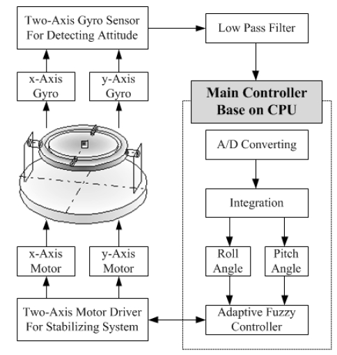
A stabilizing system considered in this paper is shown in Figure 1. It has two DOF axes in order to control the attitude of the platform in the direction of x-axis and y-axis. The composition and functional explanation of the stabilizing system are as follows. A pair of a gyro, a motor and a potentiometer is installed at each axis. The gyro detects the angular velocity about the rotation axis, the motor drives the corresponding gimbal comprising the platform, and the potentiometer measures the rotation angle of the gimbal shaft driven by the motor. The gyro signals are transferred to A/D converter through low pass filters and a multiplexer. The velocity data from the A/D converter are integrated in CPU and thus the roll angle about x-axis and the pitch angle about y-axis are calculated. The calculated angles are used in adaptive fuzzy control algorithm to generate the control signals to drive axis motors. Then, each axis motor drives to stabilize the platform.
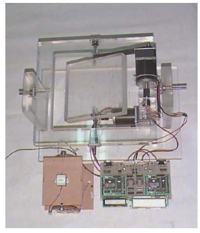
Figure 2 shows a stabilizing system physically implemented in this paper. It is used to execute several experiments to acquire results that are used to verify the effectiveness of the suggested stabilizing system.
3. Indirect Adaptive Fuzzy Control
In this section, an indirect adaptive fuzzy control theory [3] is considered, which is an active control method used to generate control inputs of gimbal axes for stabilizing the platform. The reason for using adaptive fuzzy control is that it is so adequate to control the system, just as the stabilizing system, which cannot be exactly modeled by the mathematical equation owing to the structural complexity. Indirect adaptive control theory is classified into 1st–type and 2nd–type and each has advantages and disadvantages.
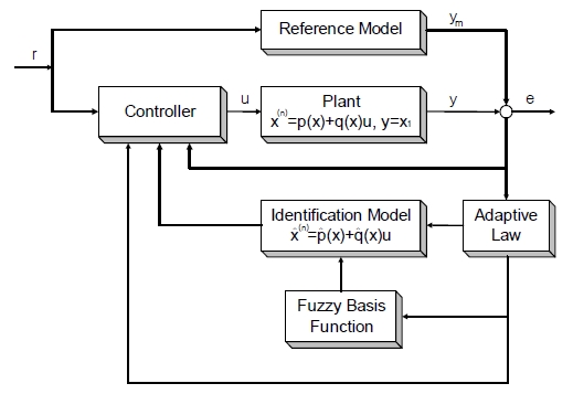
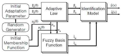
Figure 3 shows the general structure of the indirect adaptive fuzzy controller in [8]. The feature of the structure is that the control input for the unknown plant is generated using an identification model updated by the adaptive law and fuzzy basis function.
3.1 Identification Model
Consider the given nonlinear plant described by the nth-order differential equation shown in Equation (1) or Equation (2).

where p(x) and q(x) are unknown plant functions, u ∈ R and y ∈ R are an input and an output of the plant respectively, and
 is a state vector of the plant. Then, the unknown functions are identified by the indirect control algorithm given as Equation (3).

where β(x) is adaptation parameter vector and ξ(x) is fuzzy basis function vector defined as Equation (4).

3.2 Control Objective
The control objective of the indirect adaptive control is to determine the control input u = u(x | β) in order to satisfy Equation (5) based on fuzzy logic.

In this case, an adaptive law for adjusting the parameter β can be achieved under the assumption that the given system should be globally stable and all variables should be uniformly bounded.
If the functions p(x) and q(x) are known, the control law given as Equation (6) results in Equation (7) which implies the main control objective
 Equation (5).
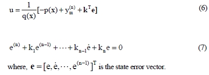
Unfortunately, the problem is that p(x) and q(x) are unknown, and so they must be identified using adaptive fuzzy control algorithm.
3.3 Certainty Equivalent Control
If unknown plant dynamics p(x) and q(x) are substituted by
 respectively, the resultant control law can be given as Equation (8).

By applying Equation (8) to Equation (2), the error differential equation can be obtained as shown in Equation (9).

And Equation (9) can be transformed into error state equation shown as Equation (10).

where Ac and bc are given as Equation (11) as followings and they can be considered as system matrix and input matrix for the derived error dynamic system given as Equation (10).
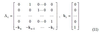
Since the control law Equation (8) was derived under the assumption that the output error should be bounded, Ac is a stable matrix, that is the roots of det(sI - Ac) = 0 are stable, there exists a positive definite matrix P which satisfy Equation (12).

If a Lyapunov function candidate Ve is chosen as Equation (13) which is positive definite except that e ≠ 0, the time derivative Ve can be derived as Equation (13).

Thus, if the time derivative is less than or equal to 0, that is
 the control law Equation (8) is very sufficient to control the given unknown plant. By the way, it is very difficult to find the control uc which forces the last term of Equation (14) less than 0 such that Ve ≤ 0.
3.4 Supervisory Control
In order to control the given unknown plant by the indirect adaptive control, it is necessary to find the control inputuwhich satisfy
 This problem can be solved by appending another control termsuto uc. It is called a supervisory control.

Substituting Equation (15) into Equation (2), the new error equation can be derived as Equation (16).

In this case, the time derivative of the Lyapunov function candidate is derived as Equation (17).

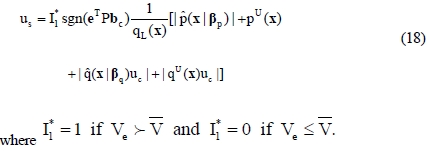
If it is assumed that pu, qu and qL are the plant function bounds such that
 and
and
 , the supervisory control us which satisfy
 can be obtained as Equation (18).
3.5 Derivation of the Adaptive Laws
It is necessary to derive the adequate adaptive law to find the adaption parameters βp and βq of the fuzzy logic system.
This problem can begin by defining the minimum approximation error ω shown in Equation (19).

where
 and
and
 are defined so as to satisfy Equation (20).

If
 are selected as fuzzy logic system according to Equations (3) and (4), the error equation given as Equation (16) can be rewritten as Equation (21).

where
 , and ξ(x) is the fuzzy basis function given as Equation (4).
In order to derive the adaptive laws, consider the Lyapunov function candidate defined as Equation (22), where ν1 and ν2 are positive constants.

The time derivative of V along the trajectory given as Equation (21) is derived as Equation (23).

Therefore, the adaptive laws for parameters pq and ββcan be obtained as Equation (24) such that


3.6 Characteristics of 1st and 2nd-type Indirect Adaptive Fuzzy Controller
The structure of the indirect adaptive fuzzy controller is classified into the 1st and the 2nd-type whether the membership functions for calculating fuzzy basis functions ξ(x) given as Equation (4) are fixed or not.
Figure 4 shows the structure of the 1st-type indirect adaptive controller. Since it uses the fixed membership functions, it has a low freedom in comprising the fuzzy logic system, it needs a large number of rules inevitably. In that aspect, it wastes much time to execute all rules for computing fuzzy basis functions. On the other hand, the adaptive laws which adjust the adaptation parameters are very simple.
Figure 5 shows the structure of the 2nd-type indirect adaptive controller. Fuzzy basis functions are composed and calculated using the adjustable membership functions in the IF parts of the fuzzy rules. Thus fuzzy logic functions
 are decided using rules smaller than those of 1st-type controller. Whereas, the adaptive laws which adjust the adaptation parameters are very complicated and the adaptive laws for adjusting membership functions must be required. For this reason, the pure 2nd-type indirect adaptive fuzzy controller is not preferable to the real-time control applications.
3.7 Suggestion of a New 2nd/1st-type Indirect Adaptive Fuzzy Controller
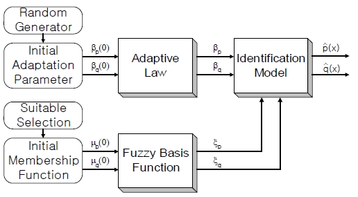
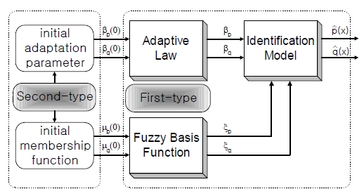
In section 3.6, the structures, advantages, and disadvantages for the 1st-type and 2nd-type indirect adaptive fuzzy controller were investigated. The 1st-type has an advantage in the type of fuzzy basis functions in the viewpoint that all basis functions are fixed. And also it has another advantage in the adaptive laws because the adaptive laws are simple. On the other hand, the 2nd-type has an advantage that it uses much smaller fuzzy rules than 1st-type because it tuned initial adaptation parameters and initial membership functions.
In this section, a new 2nd/1st-type indirect adaptive fuzzy control structure is suggested. Figure 6 presents the suggested control structure. Its control algorithm is composed by adopting the advantages of 1st-type and initial adaptation parameters and initial membership functions indirect adaptive fuzzy control structure. As meaning of the name, initial fuzzy basis functions are tuned in a way that initial adaptation parameters and initial membership functions are decided by 2nd-type in order to reduce the number of fuzzy rules. . It results in the same number of rules as those of 2nd-type structure. After then, all fuzzy basis functions are fixed during running adaption process as if it were the 1st-type case. It means that the adaptive laws are as simple as the case of 1st-type structure.
The purpose to suggest the 2nd/1st-type indirect adaptive fuzzy control structure is not only to improve the control performance but also to implement a real-time control system in spite of using low-price CPU.
4. An Attitude Control for Stabilizing System
4.1 Mathematical Model of the Stabilizing System
This chapter deals with an attitude control for the stabilizing system implemented with two DOF, as shown in Figure 2.
The plant dynamic for the roll plant of the implemented stabilizing system can be modeled as a highly nonlinear 2nd-order differential equation with parametric uncertainties given as Equation (25). The plant dynamic for the pitch plant can also be modeled as the same nonlinear 2nd-order differential equation as Equation (25). The only difference between the roll and pitch plant is the magnitudes of the least upper bounds for the uncertainties a1(t) and a2(t) in Equation (25).
Unfortunately, the exact magnitude of the each least upper bound for the two plants cannot be known.

The limits of the states x1 and x1 and the limit of the control input uwere prescribed as Equation (26) and the least upper bounds for uncertainties a1(t) and a2(t) were supposed as Equation (27).

In this case, plant constraint limits are calculated as Equation (28).

4.2 Attitude Controller Design for the Stabilizing System Physically Implemented
As referred in section 4.1, the dynamic characteristic of the given stabilizing system with two DOF is highly nonlinear and its model uncertainties caused by the structural complexity are not known.
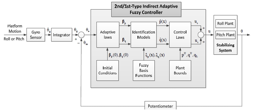
Figure 7: The control structure of the 2nd/1st-type indirect adaptive fuzzy control system for each roll and pitch plant.
The control structure of the 2nd/1st-type indirect adaptive fuzzy control system for each roll and pitch plant.
For the control of the attitude of this system, the indirect adaptive fuzzy control, named 2nd/1st-type indirect adaptive fuzzy control algorithm developed in chapter 3, was applied to the roll and pitch plant, respectively. The controller structure of each plant including hardware and software are the same. In the design process of each control system, it was assumed that the plant dynamics having been modeled in section 4.1should be unknown.
Figure 7 represents a block diagram of 2nd/1st-type indirect adaptive fuzzy control structure for each roll and pitch plant. And variables and functions described in the Figure 7 are explained as followings:
θg : integrated value of the gyro sensor output
θm : motor output angle measured by potentiometer
θe : angle error signal
uc : certainty equivalent control
us : supervisory control
u = uc = us : control input for the plant
 : identified plant functions
βp(0), βq(0) : initial adaption parameters
βp, βq : adjustable parameters by adaptive laws
ξp(x), ξq(x) : fuzzy basis functions
Two axis gyro sensors were used to measure the attitude of the platform motion, that is roll rate and pitch rate, of the stabilizing system. Therefore, the roll and pitch angle could be obtained by integrating the gyro sensor outputs. Two potentiometers were equipped on the rotating shafts of the roll gimbal and pitch gimbal for measuring the plant outputs. A digital controller was implemented based on CPU in view of hardware and software, in order to generate the control input for each roll and pitch plant. Naturally, the 2nd/1st-type indirect adaptive fuzzy control algorithm was implemented in CPU. By fully considering the computation time of the control algorithm, the sampling time for real time control could be selected as 0.05 second.
In order to identify the plant functions
 and
and
 in adaptive laws, the fuzzy basis functions ξp(x) and ξq(x) must be computed. To do this, fuzzy rules must be defined based on fuzzy membership functions.
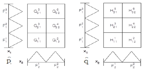
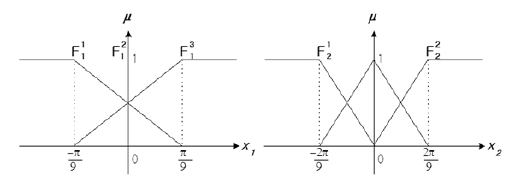
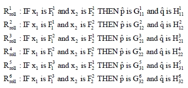
Figure 8 shows a lookup table for generating fuzzy rules necessary to the roll plant control system design. Figure 9 shows membership functions for states x1 and x2 of the roll plant.
Figure 9 shows membership functions for states x1 and x2 of the roll plant, which are used in fuzzy rules.
By using Figures 8 and 9, the corresponding fuzzy rules for the roll plant can be arranged as followings:
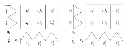
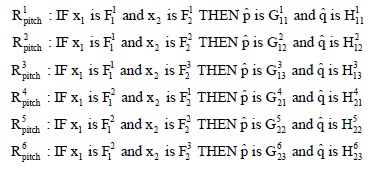
In the similar manner, a lookup table and membership functions must be defined for generating fuzzy rules necessary to the pitch plant control system design. Figures 10 and 11 show them, respectively.
By using Figures 8 and 9, the corresponding fuzzy rules for the pitch plant can be arranged as followings:
4.3 Experiments and Discussion for Results
In order to test the possibility of the suggested control system, several experiments were executed using the stabilizing system shown in Figure 2. As a method to generate the platform motion of the stabilizing system, the platform on which the gyro sensors are installed was swung with the angle range about -30o ≤ θg ≤ 30o by using hands for each roll and pitch plant. The angular velocity of the gyro platform was measured about
 and the swing frequency was about 1/6Hz, which was similar to the rolling and pitching motion of ships.
Figure 12 shows the experimental results of the simple feedback system for the roll plant without controller. The integrated gyro sensor output is exerted on the feedback system as a reference signal and thus the potentiometer output is just the output of the system.
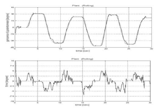
Angular position responses of the simple feedback system for the roll plant with time varying platform motion.
The upper figure in Figure 12 is to compare the integrated gyro sensor output with the potentiometer output. The lower figure in Figure 12 shows the output error between the integrated gyro sensor output and the potentiometer output. From the figure, it is known that the transient response of the simple feedback system for the roll plant reveals a considerable overshoot with the maximal error about ±7o.
Figure 13 shows the experimental results of the 2nd/1st-type indirect adaptive fuzzy control system for the roll plant. From the figures, it is known that the transient response of the suggested control system for the roll plant was improved in view of an overshoot. Although the transient response revealed a poor response similar to that of the simple feedback system during transient time, it was improved within the maximal error ±2.0o as time was passed to steady state.
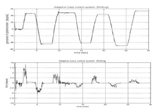
Angular position responses of the suggested control system for the roll plant with time varying platform motion.
Figure 14 shows the experimental results of the simple feedback system for the pitch plant without controller. The upper figure in Figure 14 is to compare the platform motion as a reference input with the feedback system output for pitch plant. The lower figure in Figure 14 shows the output error between the platform motion and the system output. From the figure, it is known that the transient response of the simple feedback system for the pitch plant reveals a overshoot with the maximal error with the range -1.0o to 6.0o. A distinguished feature of the error response is that the error was biased on positive side. The reason for this bias is just the influence of the mass unbalance caused by the geometrical complexity of the pitch plant.
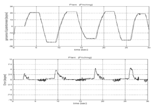
Angular position responses of the simple feedback system for the pitch plant with time varying platform motion.
Figure 15 shows the experimental results of the 2nd/1st-type indirect adaptive fuzzy control system for the pitch plant.
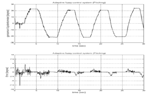
Angular position responses of the suggested control system for the pitch plant with time varying platform motion.
From the figures, it is known that the transient response of the suggested control system was improved well in view of the overshoot and the output error. The steady-state response was also improved as time was passed within the maximal error ±2.5o and also the bias trend was disappeared.
In the conclusion, the possibility of the indirect adaptive fuzzy control system suggested in this paper for the stabilizing system, was convinced. However, the control performance in terms of the overshoot and the output error in steady-state could not be highly improved. It is noted that the only six fuzzy rules were used to compute the fuzzy basis functions. If the more numbers of fuzzy rules are used, the better performance of the fuzzy control system can be achieved.
5. Conclusions
In this paper, a method to comprise the control system for the stabilizing system with two DOF was suggested. The suggested method is the 2nd/1st-type indirect adaptive fuzzy control algorithm utilizing advantages of 1st-type and 2nd-type indirect adaptive control algorithm. And the control system for the roll and pitch plant of the stabilizing system was implemented in view of hardware and software. Several experiments using the implemented stabilizing system were executed and then results obtained from experiments were analyzed. Conclusively, the effectiveness of the suggested control algorithm was assured by analyzing the experimental results.
Acknowledgments
This paper is extended and updated from the short version that appeared in the Proceedings of the International symposium on Marine Engineering and Technology (ISMT 2014), held at Paradise Hotel, Busan, Korea on September 17-19, 2014.
References
- M. Park, and M. Lee, “Identification of motion platform using the signal compression method with pre-processor and its application to siding mode control”, Journal of Mechanical Science and Technology, 16(11), p1379-1394, (2002).
-
H. Liang, L. Li, and J. Ou, “Fully coupled time-domain simulation of dynamic positioning semi-submersible platform using dynamic surface control”, Journal of Ocean University of China, 13(3), p407-414, (2014).
[https://doi.org/10.1007/s11802-014-2066-y]

-
W. Liang, and Z. Wang, “Several experience on automatic sun tracking system”, Proceedings of ISES World Congress 2007, 5, p1768-1772, (2009).
[https://doi.org/10.1007/978-3-540-75997-3_362]

-
S. Liu, H. Che, and L. Sun, “Research on stabilizing and tracking control system of tracking and sighting pod”, Journal of Control Theory and Applications, 10(1), p107-112, (2012).
[https://doi.org/10.1007/s11768-012-9152-8]

-
A.M. Kostygov, A. V. Kychkin, D. A. Dadenkov, and A. A. Kaverin, “Fuzzy control of wheel drives of a mobile intelligent platform moving along a predetermined path”, Russian Electrical Engineering, 84, p634-637, (2014).
[https://doi.org/10.3103/S1068371213110060]

- A. Filipescu, V. Minzu, A. Filipescu, and E. Minca, “Discretetime sliding-mode control of a mobile platform with four driving/steering wheels”, Advances in Automation and Robotics, 1, p401-409, (2012).
-
Y. Yang, J. Wu, and W. Zheng, “Concept design, modeling and station-keeping attitude control of an earth observation platform”, Chinese Journal of Mechanical Engineering, 25(6), p1245-1254, (2012).
[https://doi.org/10.3901/CJME.2012.06.1245]

- L. Wang, Adaptive Fuzzy Systems and Control: Design and Stability Analysis, Prentice-Hall Inc., (1994).
-
L. Wang, and J. Mendel, “Fuzzy basis function, universal approximation, and orthogonal least square learning”, IEEE Transaction on Neural Network, 3(5), p807-814, (1992).
[https://doi.org/10.1109/72.159070]


