A sun tracking control system using two DOF active sensor array
Copyright © The Korean Society of Marine Engineering
This is an Open Access article distributed under the terms of the Creative Commons Attribution Non-Commercial License (http://creativecommons.org/licenses/by-nc/3.0), which permits unrestricted non-commercial use, distribution, and reproduction in any medium, provided the original work is properly cited.
In our daily life, the need of energy increases day by day. However, the amount of natural resources on the earth is limited and thus gaining renewable energy as an energy resource is one of the important and urgent problems. Solar energy is one of the most popular available energy sources that can be converted into electricity by using solar panels. In order for solar panels to produce maximal output power, the incident angle of the sunlight needs to be persistently perpendicular to the solar panel. By the way, most of the solar panels are installed at fixed position and direction. Therefore, as the sun’s position changes, it is impossible to produce maximal output power inevitably. To improve this problem, in this paper, a sun tracking system using two degree-of-freedom (DOF) active sensor array is proposed so that the solar panel may always direct sunlight perpendicularly. And also a series of software, such as a search mode and a holding mode, which can control the developed sun tracking system is developed. Several experiments using the implemented sun tracking system are executed and the effectiveness of the system is verified from the experimental results.
Keywords:
Sun tracking system, Two degree-of-freedom active sensor array, Holding mode, Search modeIntroduction
Nowadays, concerns about the development of alternative energies are increased day by day, and naturally researches on the development of alternative energies are reported in many country of the world [1][2]. Moreover, it is very important to find alternative energies in this country which has little resources. There are many types of energies which belong to alternative energy, such as solar energy, wave energy, wind energy, and so forth. Solar energy is one of the most attractive alternative energies for the future because it is clean, consistently supplied, and widely distributed throughout the earth. Especially, it has high potential to be used in this country which has much better daylights a year.
By the way, the density of the solar energy is too low to use the solar energy di ectly and pay much cost to use it. In order to use the solar energy
effectively it must be needed to comprise a system to collect the sunlight. To comprise the sunlight collection system, first of all, a sun tracking system is necessary to track the sun continuously during daylight [3]-[5]. Lots of researches for sun tracking system have been reported and their results have been applied to real industrial world [6]-[10]. But most of them use passive sensor methods or computation methods as sun tracking method. However, their methods cannot have the ability to track the sun when installation position or orientation of the sun tracking system is changed.
This paper suggests a sun tracking system which can track the sun during daylight regardless of the change of installation position and/or orientation. The suggested system would be especially adequate to applications for ship of which position and orientation are changed continuously. The applied method to track the sun is an active sensor method with a two DOF sensor array. And this paper also develops all necessary software which can operate the overall tracking system. The representative software comprises a searching mode algorithm and a holding mode algorithm. Especially, the algorithm called holding mode is very useful to reduce the execution time for the real time tracking and to save energy for driving the system.
Composition of a Sun Tracking System
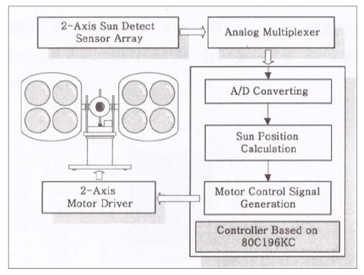
The following Figure 1 presents the composition of a sun tracking system suggested in this paper. It comprises a sun tracking sensor module, a two-axis driving motor module, and a signal processing and control module. The sun tracking sensor module is composed of two DOF sensor array, a lens assembly, and a focus adjustable screw set. The two-axis driving motor module is composed of two DC motors and motor driving circuits. And it drives the sensor module about two rotating axes such as elevation and azimuth axis independently. The signal processing and control module is composed of a multiplexer, an A/D converter, and a CPU-based controller.
2.1 Sun Tracking Sensor Module
Most conventional sensor methods referred to references adopt four photo sensors mounted on east side and west side for sun tracking in azimuth direction, and mounted on south side and north side for tracking in elevation direction with reference to an installation position of sun tracking system. The sun tracking mission in azimuth direction is finished when the outputs of east and west sensor are equal each other. The mission in elevation direction is finished in the same manner using south and north sensor. In this method, sensors installed outside causes a problem at maintenance. And also, it may take much time to finish the exact sun tracking. However, if the installation position or orientation of the sun tracking system is changed, a decision for the directions such as east and west must be executed newly.
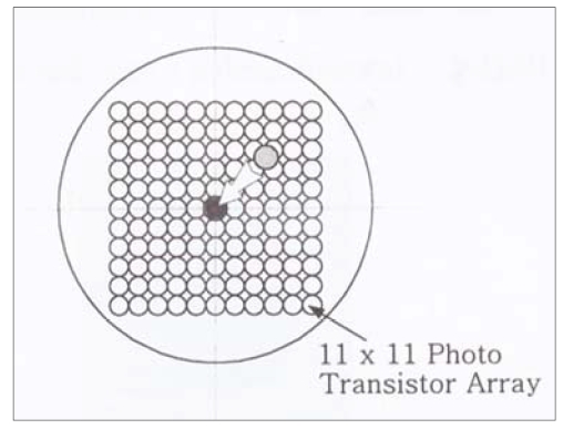
In order to avoid the above inconveniences and to give independence on the change of installation position and orientation, a sensor array with two DOF is adopted in this paper. Figure 2 presents a method to comprise the sensor array composed of 11 ⅹ 11 photo transistors.
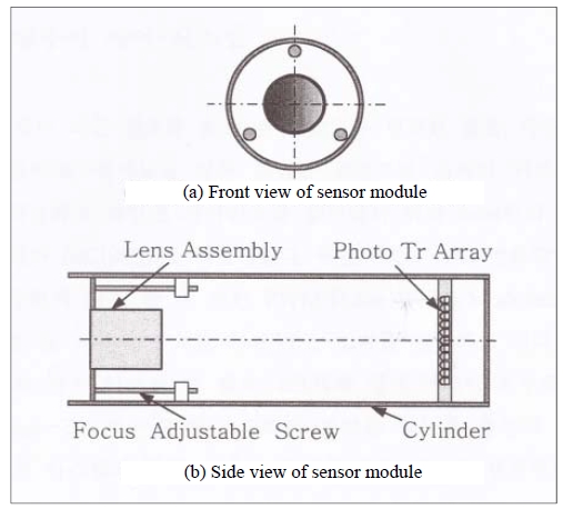
In order for the two DOF sensor array to have the sun tracking function, a sunlight focus on the sensor array must be made through a lens assembly.
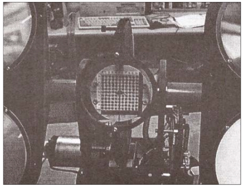
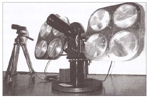
Moreover, the lens assembly must have the function of thermal filter to eliminate the heat resulted from focusing the sunlight. The technology is one of the key solution for comprising the suggested sun tracking system. Figure 3 presents the structure of the sun tracking sensor module and Figure 4 shows a photo of the sensor module implemented. A sun tracking method using this two DOF sensor array will be explained later in section 3.
2.2 Signal Processing and Control Module
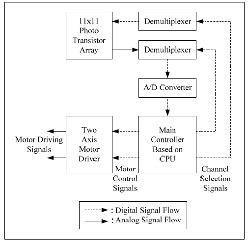
The analog multiplexer is necessary to transfer sensor output signals from 11 x 11 sensor arrays into an A/D converter in successive order by using scan code method. The A/D converter converts analog sensor signals from the multiplexer into digital sensor data when a main controller executes interrupt routine for A/D conversion.
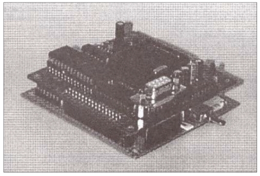
Figure 5 explains the signal flows in the signal processing and control module and Figure 6 shows the photograph of hardware physically implemented.
The main controller executes the decision of focus location on the sensor array and calculates the rotation angles for azimuth and elevation axis in order to move the focus to the center on the sensor array. And then, it generates PWM signals corresponding to the rotation angles to drive two DC motors about azimuth and elevation axis. When the focus lies on the center, the sensor module exactly directs the sun and the sensor array panel is perpendicular to the sunlight.
Development of software for driving the sun tracking system
3.1 Control Software for the Overall System
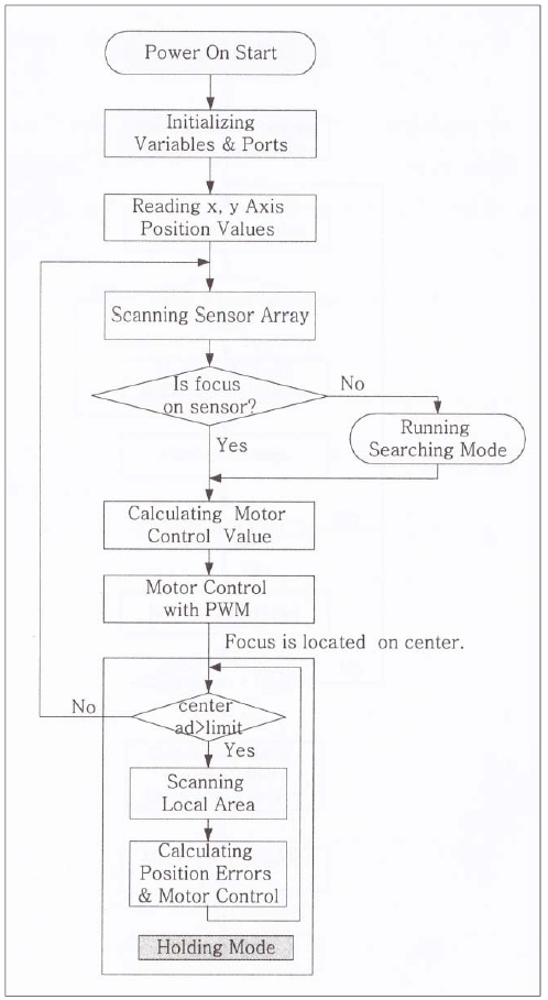
When the power of the sun tracking control system is on initially, each port of the control system is initialized and a main CPU reads x and y position of the sunlight focus on the sensor array panel through A/D conversion. And then, CPU reads current angular positions of DC motors. If the focus is on the sensor panel, a series of routine to track the accurate sun position is executed to move the focus into the center of the sensor panel by generating control signals. If the focus cannot be found on the sensor panel, a series of searching mode must be accomplished to find the sun position.
Figure 7 describes the flowchart to operate the sun tracking control system mentioned in the above.
3.2 Search Mode Software for Searching the Sun Position
If a sunlight focus is not on the sensor array, a series of process to detect the sun position is accomplished so that a focus may resultantly lie on the sensor panel. The process is called the searching mode.
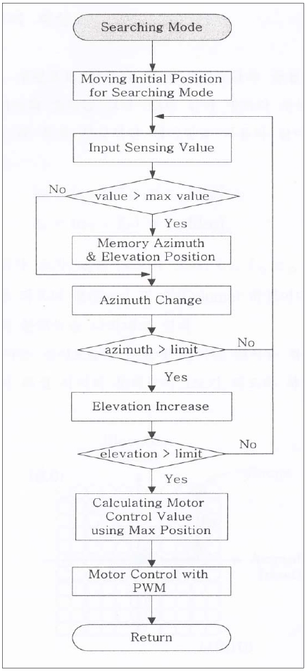
The searching mode is processed in the following manner. At first, the sun tracking system is moved at initial position for searching mode and then the CPU checks the current angular positions in the azimuth and elevation direction.
At second, under the current elevation position, azimuth motor is rotated from left-hand to right-hand limit angle position.
At third, if the focus is not found on the sensor array, the elevation angle is changed with defined increment by rotating elevation motor and then azimuth motor is rotated from left-hand to right-hand limit angle position.
The second and third step is repeated until the focus is found on the sensor array panel.
Figure 8 shows the flowchart of the process for the searching mode software mentioned in the above.
3.3 Calculating Command Inputs for Two Axis Controllers to Track the Exact Sun Position Based on Sensor Array
If a focus is on the sensor array by accomplishing the searching mode process, command inputs of two axis controllers for azimuth and elevation control must be generated in order for the sensor module to meet sunlight perpendicularly, that is, in order to track the sun exactly. Figure 9 explains a method to calculate the command inputs for motor controller. If the focus on an arbitrary sensor of the sensor array can be moved into the center of the sensor array, the sun tracking system can track the sun exactly.
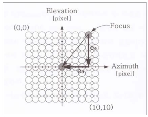
A method to generate command inputs of two axis motor controllers to track the sun position exactly.
In order to move the current focus into the center of the sensor array, angle errors corresponding to the position errors in Figure 9 between current coordinates of the focus and center coordinates on the sensor panel, must be calculated:

where ݁ea is an angle error along the azimuth axis, ee is an angle error along the elevation axis, cr, fr, cc and fc are the row and column coordinates of the center of the sensor panel and the current focus, respectively. re and ra are angle resolutions in azimuth and elevation, respectively.
The above equations expressed by unit [deg] can be converted into the equations expressed by unit [A/D digital value] for convenience,

where ce and ca are absolute reference values converted as A/D digital values and pe and pa are current elevation and azimuth angular position values of the sun tracking system read by A/D converter.
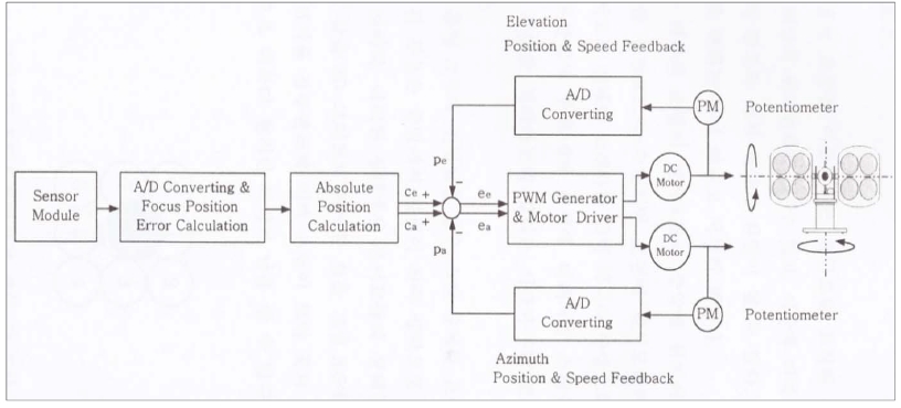
Conclusively, the sun tracking control system executes the sun tracking according to the functional block diagram as shown in Figure 10.
4. Experiments and Discussions for Results
4.1 Possibility Test of the Sun Tracking Using the Sensor Array
Figure 11 shows a photograph of the sun tracking control system used for experiments.
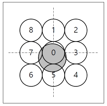
When a focus is nearly on a photo sensor of the sensor array, it is called the focus is in the holding mode. In the holding mode, only 9 sensor outputs from 0 to 8 as shown in Figure 12 are converted with priority. In this case, the only holding mode algorithm in Figure 7 is accomplished.
This means that the searching time for the sun and the converting time for sensor arrays are saved at the same time.
Naturally, their A/D converted output values are larger than the other sensor values.
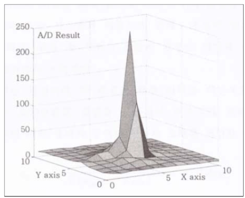
In order to verify this, an experiment was executed when a focus was nearly on the center in the holding mode as shown Figure 12. For experiment, all sensor outputs were acquired exceptionally beyond the holding mode. Figure 13 shows the measured sensor output values displayed in 3D graph. From the figure, it is apparently known that the output of the sensor in the center is much greater than other sensors.
Figure 14 shows the sensor output results using digital data expressed as the A/D converted values. It is seen that the centered sensor located at (5, 5) position in x-y coordinates of the sensor array produces maximal output.
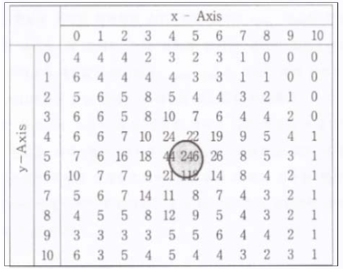
Sensor outputs expressed as A/D converted digital values when a focus is nearly on the center corresponding to Figure 13.
Therefore, it is concluded that whenever the output of the centered sensor of the two DOF sensor array is maximal, the sun tracking system always directs the sun almost normally.
4.2 Possibility Test for Searching the Sun
Whenever a focus is not in the sensor array, a searching mode algorithm must be accomplished regardless of the initial angular positions of azimuth and elevation axis in the sun tracking control system.
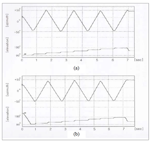
Figure 15 shows the searching mode results for finding the sun position for various initial angular positions. According to the searching mode algorithm, the elevation angle was initialized at angle 90 degree and then incremented from 90 degree to 180 degree as soon as the azimuth searching was finished within -50 degree to 50 degree range or reverse range. It is seen that the last position is near the holding mode position from the result of sun tracking.
Figure 16 shows a sun tracking process using the GUI screen which was designed for monitoring sensor states during tracking control process. The initial focus on (2,1) coordinate in the sensor array moved to (5,5) coordinate, the center of the sensor array. It means that the face of the sensor module directs the sunlight perpendicularly and thus the sun tracking process has been finished.
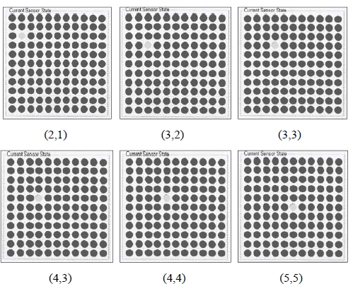
A sun tracking control process from (2,1) to (5,5) corresponding to the center on the GUI screen for monitoring sensor states.
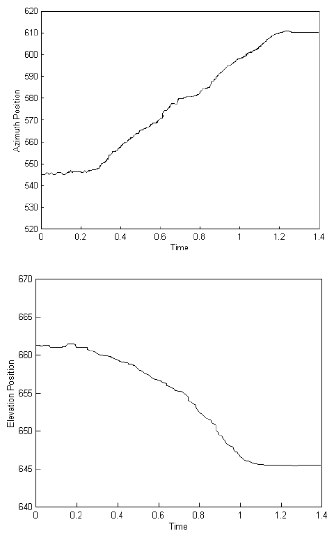
Figure 17 shows the tracking performance in the azimuth and elevation angle control for the case of Figure 16. In order to move the focus on (2,1) coordinate to (5,5) coordinate, the process must be operated in the direction that the azimuth angle is increased from right to left and also the elevation angle is decreased from top to down. Figure 17 explains the above mentioned process exactly.
Conclusions
In order to utilize the sunlight effectively, a sun tracking system must be composed in order to track the sun continuously during daytime.
In this paper, a sun tracking control system which can track the sun regardless of the change of installation position and/or orientation was proposed. As the system adopts the active sensor method for tracking the sun, it is especially adequate to applications such as ships or moving vehicles of which position and orientation are changed continuously. The active sensor method to track the sun is composed of two DOF sensor array. And this paper also developed all software necessary to operate the overall sun tracking control system. The main software is composed of the searching mode algorithm and the holding mode algorithm. Through several experiments, it turned out that the sun tracking control system including the hardware and the software was well operated and thus it is very effective and useful system for the sun tracking control.
Acknowledgments
This paper is extended and updated from the short version that appeared in the Proceedings of the International symposium on Marine Engineering and Technology (ISMT 2014), held at Paradise Hotel, Busan, Korea on September 17-19, 2014.
References
- Y. H. Kang, “A possibility of regenerable energy and its technology trend in Korea”, Proceedings of Regenerable Energy Workshop, (1998).
- Solar tracking & wind energy, http://www.linak.com Accessed September 30, 2014.
- A. Y. Hasan, “Design and implementation of a fuzzy logic computer-controlled sun tracking system”, Proceedings of the IEEE International Symposium on Industrial Electronics, 3, p1030-1034, (1999).
-
J. N. Khalifa, and S. S. Almutawalli, “Effective of two axis sun tracking on the performance of compound parabolic concentrator”, Energy Conversion and Management, 39(10), p1073-1079, (1998).
[https://doi.org/10.1016/S0196-8904(97)10020-6]

- T. Hawat, “Sun tracker for atmospheric remote sensing”, Society of Photo-Optical Instrument Engineers, p1633-1642, (1998).
-
Y. Sai, R. Ma, and X. Yang, “Design and analysis of a sun tracking system”, Proceedings of Advanced Research on Computer Science and Information Engineering, International Conference Part I, p8-14, (2011).
[https://doi.org/10.1007/978-3-642-21402-8_2]

-
W. Y. W. Adrian, V. Durairajah, and S. Gobee, “Autonomous dual axis solar tracking system using optical sensor and sun trajectory”, The International Conference on Robotic, Vision, Signal Processing & Power Applications Part VI, 507(520), (2014).
[https://doi.org/10.1007/978-981-4585-42-2_58]

-
B. M. Abdurakhmanov, S. K. Akbarov, A. I. Anarbaev, U. A. Tadzhiev, and R. A. Zakhidov, “A photoelectric station with two-axis sun tracking”, Applied Solar Energy, 43(3), p140-143, (2007).
[https://doi.org/10.3103/S0003701X0703005X]

-
W. Liang, and Z. Wang, “Several experience on automatic sun tracking system”, Proceedings of ISES World Congress, 5, p1768-1772, (2009).
[https://doi.org/10.1007/978-3-540-75997-3_362]

- W. Wei, and J. Su, “Anti-wind sun tracking system with optomechatronics technology”, Advances in Intelligent and Soft Computing, 112(663), p670, (2012).

