CFD analysis of geometric parameters that affect dean flow in a helical microchannel
Copyright © The Korean Society of Marine Engineering
This is an Open Access article distributed under the terms of the Creative Commons Attribution Non-Commercial License (http://creativecommons.org/licenses/by-nc/3.0), which permits unrestricted non-commercial use, distribution, and reproduction in any medium, provided the original work is properly cited.
Due to the presence of Dean flow in curved ducts, helical channels have drawn attention recently because of the practical industrial applications. The manipulation of fluids through microfluidic devices is widely used in many scientific and industrial areas. In the present study, numerical simulations were performed on a helical microchannel to predict the impact of different design parameters that affect Dean flow. Important geometric parameters such as the channel cross section, pitch, radius of curvature, and number of turns were considered for the analysis. The study also incorporates the effect of varying flow rate on Dean flows. It was found from the simulation results that microchannel cross section and pitch have a significant impact on maintaining the Dean flow, compared to the radius of curvature, number of turns, and flow rate.
Keywords:
Helical microchannel, Dean flow, Parametric study, CFDNomenclature
ρ density of fluid (kg/m3)
V average fluid velocity (m/s)
Dh hydraulic diameter (m)
μ dynamic viscosity of fluid (kg/m×s)
R radius of curvature (m)
Re Reynolds number
De Dean number
w width of the microchannel (μm)
h height of the microchannel (μm)
u fluid velocity (m/s)
Si mass distributed per unit mass
h thermal enthalpy
QH heat source per unit volume
Ԏik viscous shear stress tensor
qi diffusive heat flux
1. Introduction
Helical microchannels are widely applied in many areas because of their compact structure and the Dean flow that occurs within them [1]. Dean flows through curved channels are getting more attraction, not only because of the practical importance for various industrial applications but also because of the physically interesting phenomena [2]-[4]. Curvature in a duct causes centrifugal forces to act on the flowing fluid, which in turn results in a secondary flow that is perpendicular to the main axial flow [5]. This secondary flow has two counterrotating vortices that move fluid from the inner wall, through the duct center, and then towards the outer wall. After reaching the outer wall, the fluid then travels back to the inner wall, following the wall. These counter-rotating vortices are referred to as Dean flows [6]-[8]. These flow principles can be widely applied in microfluidic devices for manipulating fluids, which are used in many fields of science and technology [9].
Flow in microdevices has applications in many different areas, such as biomedical engineering, electro kinetics, mixing and dispersion, and multiphase flow. For instance, the development of Dean flow in a curved microchannel helps to enhance the lateral migration of particles, which in turn leads to the separation of particles [7]-[9]. With a shear-induced inertial lift force and Dean drag force, an alteration of larger and smaller particle equilibrium positions can be achieved by redistributing the velocity profile [10]. Dean flow plays a critical role in separation of particles, because in addition to focusing the larger particles in a single stream, the Dean flows will transpose the smaller particles from the inner half to the outer half of the microchannel cross section, which in turn results in migration of the particles [2][8][9]. In the present study, numerical simulations were performed on a helical microchannel to predict the effect of parameters such as channel cross section, pitch, radius of curvature, number of turns, and flow rate on Dean flow.
2. Numerical Simulation
2.1 CFD Analysis
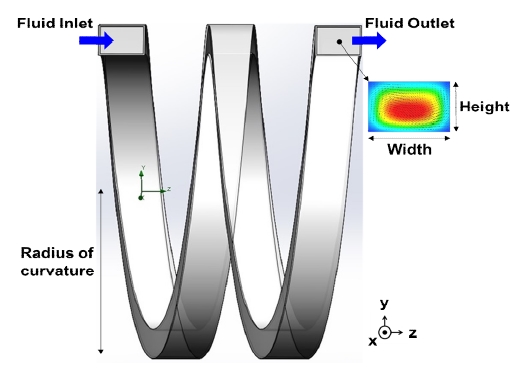
The numerical simulations were carried out with the aid of the commercial CFD code SolidWorks Flow Simulation. The 3D physical models for the analysis were modeled in SolidWorks, as shown in Figure 1. The flow was set to be steady, incompressible, and non-turbulent. The properties of the fluid, such as density and viscosity, were set equal to those of water (density = 991 kg/m3 and viscosity = 0.001 Pa×s). The inlet boundary condition was a fixed flow rate, while the outlet was set to zero pressure with no viscous stress condition. A no slip condition was enforced at the channel walls. Laminar flow equations were used to solve the specified conditions. Grid independence studies were conducted from coarser to finer meshes, until the optimal mesh size was found.
2.2 Governing Equations
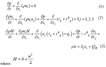
Flow simulation works on the basis of Navier-Stokes equation, which are formulations of mass, momentum and energy conservation laws for fluid flows. It uses one system of equations to solve the laminar and turbulent flows which will calculate the flow according to the given conditions. The governing equations can be written in a Cartesian coordinate system with an angular velocity through the axis of rotation in the conservation form as,
2.3 Model Validation
To assess the accuracy of the CFD results obtained from Flow Simulation, a validation study was conducted by comparing the
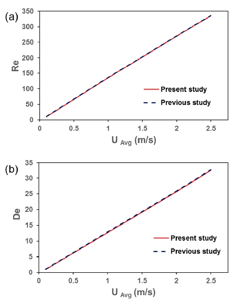
CFD results with those in a spiral microchannel by Martel et al. [10]. In the present study, a 5 turned rectangular spiral microchannel with an aspect ratio of 8 and a radius of curvature = 1.5 mm was modeled in SolidWorks and simulated in Flow Simulation. The simulations were performed under varying velocities of 0.1 to 2.5 m/s in the spiral microchannel, with the assumptions and boundary conditions mentioned above. Figure 2 shows that the results obtained are in very good agreement with the previous study. The calculated values of Reynolds number (Re) from Figure 2 (a) and Dean number (De) from Figure 2 (b) showed a linear relationship with varying velocities, which was found to be in the same range as that of the previous study.
3. Results and Discussion
Helical microchannel design is based on geometric factors such as channel cross section, pitch, number of turns and radius of curvature. Therefore, it is very important to perform a case– by-case parametric study by varying each individual parameter while fixing the others as constant, to determine the impact of each parameter on Dean flow. The advantage of such a study is that an optimum design condition for the helical microchannel could then be derived by researchers according to the type of application in their respective field of interest. The magnitude of the Dean flow is represented by using the dimensionless Dean number (De) and it can be calculated mathematically by using the relation [7][8]:

3.1 Effect of channel cross section
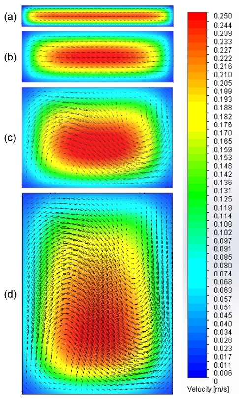
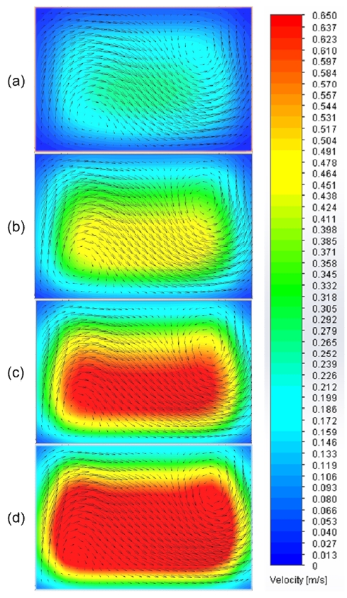
Figure 3 illustrates the variation in velocity vectors for the helical microchannel at a flow rate of 0.4 mL/min, 1 mL/min, 2 mL/min and 4 mL/min corresponding to four different aspect ratios: 7.5 (w/h = 600 μm/80 μm), 3 (w/h = 600 μm/200 μm), 1.5 (w/h = 600 μm/400 μm), and 0.75 (w/h = 600 μm/800 μm). In this case, along with the microchannel cross section, channel flow rate was also varied so that the effect on channel cross section can be clearly studied by maintaining a constant average input velocity, and all other parameters were fixed: Pitch = 1 mm, radius of curvature = 2.5 mm, and number of turns = 2. From the contours, we can see a disappearance of rotating Dean flow vectors at the low cross sectional height of 80 μm when compared to the higher channel heights. This means that in order for a proper Dean flow to occur in a helical microchannel, the channel aspect ratio (w/h) is an important factor; the height should not be too small in comparison to the width. At higher channel cross sectional size the Dean flow is maintained consistently, even at a height of 800 μm. The calculated Dean number takes values of De = 0.5, 33.5, 64.9, and 100.1 for channel heights of 80, 200, 400, and 800 μm, respectively. The changes in Dean number were due to the change in hydraulic diameter with respect to the average velocity of the flowing fluid.
3.2 Effect of pitch
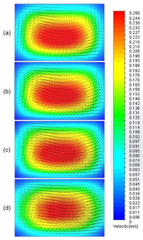
A helix with 2 turns, radius of curvature 2.5 mm, and aspect ratio of 1.5 (w/h = 600 μm/400 μm) was modeled at pitch values of 1, 1.5, 2, and 2.5 mm. Figure 4 shows the variation in velocity with Dean vortices at different pitch values under a flow rate of 2 mL/min. From the figure, it can be seen that as the pitch value increases from 1 to 2.5 mm, the Dean flow vortices begin to disappear due to the increase in distance between the two channel loops. Therefore, when designing a helical microchannel, the pitch value should be maintained at a minimum with respect to the microchannel aspect ratio. Furthermore, the calculated Dean number shows a decrease in its value from De = 64.9 for 1 mm pitch to De = 60.3 for 2.5 mm pitch, which indicates a decrease in the velocity in the microchannel fluid flow that is associated with the increase in pitch.
3.3 Effect of radius of curvature
Figure 5 depicts the variation in velocity with Dean flow vectors in the microchannel cross section at a flow rate of 2 mL/min for different curvatures. A helical microchannel with 2 turns, pitch of 1 mm, and aspect ratio of 1.5 (w/h = 600 μm/400 μm) was considered in this case. It can be seen from the contours that as the radius of curvature increases from 1 to 2.5 mm, the Dean flow patterns are not greatly distorted in the microchannel cross section, but there is a decrease in the Dean number value from De = 96.7 at 1 mm radius of curvature to De = 67.9 at 5 mm radius of curvature. This is because of the decrease in velocity in the helical microchannel with an increase in De = 64.9 at 5 mm radius of curvature. Therefore, the effect of the radius of curvature on Dean flow vortices is less significant than that of the cross sectional size and pitch.
However, a low radius of curvature can cause a high flow velocity, which may be an advantage for certain microfluidic applications.
3.4 Effect of number of turns
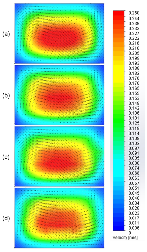
A helical microchannel with a pitch of 1 mm, radius of curvature of 2.5 mm, and aspect ratio of 1.5 (w/h = 600 μm / 400 μm) was modeled with 2, 4, 6, and 8 turns. Fig. 6 illustrates the variation in velocity with Dean flow vortices under a flow rate of 2 mL/min in the microchannel cross section for different numbers of turns. It can be visualized from the contours that as the number of turns increases, the Dean flow vortices are maintained consistently throughout the flow. The increase in the number of turns does not have sufficient effect on the Dean flow to distort its pattern. However, there is a decrease in flow velocity as the number of turns increases due to the increase in length of the helical channel, which causes the value of Dean number to decrease from De = 64.9 for 2 turns to De = 59 for 8 turns. Therefore, for a helical microchannel with more turns, a high input flow rate is recommended.
3.5 Effect of flow rate
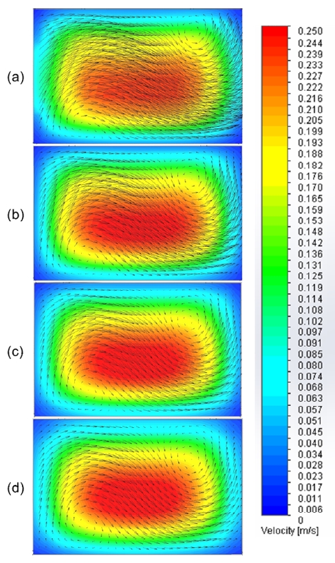
Figure 7 illustrates the variation in velocity with Dean flow vortices in the microchannel cross section for different flow rate conditions: 2, 4, 6, and 8 mL/min. A helical microchannel with 2 turns, pitch of 1 mm, radius of curvature of 2.5 mm, and aspect ratio of 1.5 (w/h = 600 μm/400 μm) was considered for this case. It is clear from the contour that as the flow rate increases, the Dean flows are maintained throughout the flow variation by the generation of stronger Dean vortices than in the other cases. The increase in flow rate obviously results in an increase in the Dean number value from De = 64.9 for 2 mL/min to 261.4 for 8 mL/min. Therefore, a properly designed helical microchannel with a better flow rate can give consistent flow distribution with good Dean flow patterns, which can be widely applied to relevant application areas.
4. Conclusion
In the present study, CFD based simulations were performed on a helical microchannel to determine the impact of various design parameters that affect the rotating Dean flow vortices. Simulations were carried out for following parameters: channel cross section, pitch, radius of curvature, number of turns, and flow rate. From the results, it was found that channel cross section and pitch have a significant impact on Dean flow vectors that are maintained in the microchannel cross section, in comparison to the other parameters. Furthermore, the flow rate study indicates that an optimal flow rate can cause strong Dean flow vortices. Therefore, by considering the above-mentioned parameters, a helical microchannel can be designed and developed efficiently with consistent Dean flow patterns, suitable for use in various microfluidic application areas.
Acknowledgments
This research was supported by grants from the Basic Science Research Program (NRF-2013R1A1A2059539) through the National Research Foundation (NRF) funded by Ministry of Education and from the Human Resources Development Program (20134010200580) of the Korea Institute of Energy Technology Evaluation and Planning (KETEP) funded by the Ministry of Trade, Industry and Energy, Republic of Korea. Bibin Prasad was funded by the Global Scholarship Program for Foreign Graduate Students at Kookmin University in Korea.
This paper is extended and updated from the short version that appeared in the Proceedings of the International symposium on Marine Engineering and Technology (ISMT 2014), held at Paradise Hotel, Busan, Korea on September 17-19, 2014.
References
-
T. J. Rennie, and V. G. S. Raghavan, “Numerical studies of a double-pipe helical heat exchanger” , Applied Thermal Engineering, 26(11-12), p1266-1273, (2006).
[https://doi.org/10.1016/j.applthermaleng.2005.10.030]

-
W. R. Dean, “XVI. Note on the motion of fluid in a curved pipe”, The London, Edinburgh, and Dublin Philosophical Magazine and Journal of Science, 4(20), p208-223, (1927).
[https://doi.org/10.1080/14786440708564324]

-
W. R. Dean, “LXXII. The stream-line motion of fluid in a curved pipe (Second paper)”, The London, Edinburgh, and Dublin Philosophical Magazine and Journal of Science, 5(30), p673-695, (1928).
[https://doi.org/10.1080/14786440408564513]

-
H. Chen, B. Zhang, and J. Ma, “Theoretical and numerical analysis of convective heat transfer in the rotating helical pipes”, International Journal of Heat and Mass Transfer, 46(25), p4899-4909, (2003).
[https://doi.org/10.1016/S0017-9310(03)00350-8]

-
H. Ito, “Flow in curved pipes”, JSME International Journal: bulletin of the JSME, 30(262), p543-552, (1987).
[https://doi.org/10.1299/jsme1987.30.543]

-
D. G. Prabhanjan, T. J. Rennie, and G. S. V. Raghavan, “Natural convection heat transfer from helical coiled tubes”, International Journal of Thermal Sciences, 43(4), p359-365, (2004).
[https://doi.org/10.1016/j.ijthermalsci.2003.08.005]

-
G. Guan, L. Wu, A. A. S. Bhagat, Z. Li, P. C. Y. Chen, S. Chao, C. J. Ong, and J. Han, “Spiral microchannel with rectangular and trapezoidal cross-sections for size based particle separation”, Scientific Reports, 3, p1475, (2013).
[https://doi.org/10.1038/srep01475]

-
S. S. Kuntaegowdanahalli, A. A. S. Bhagat, G. Kumar, and I. Papautsky, “Inertial microfluidics for continuous particle separation in spiral microchannels”, Lab on a Chip, 9(20), p2973-2980, (2009).
[https://doi.org/10.1039/b908271a]

-
N. Nivedita, and I. Papautsky, “Continuous separation of blood cells in spiral microfluidic devices”, Biomicrofluidics, 7(5), p054101, (2013).
[https://doi.org/10.1063/1.4819275]

-
J. M. Martel, and M. Toner, “Inertial focusing dynamics in spiral microchannels”, Physics of Fluids, 24(3), p032001, (2012).
[https://doi.org/10.1063/1.3681228]

-
S. A. Berger, L. Talbot, and L. S. Yao, “Flow in curved pipes”, Annual Review of Fluid Mechanics, 15(1), p461-512, (1983).
[https://doi.org/10.1146/annurev.fl.15.010183.002333]

- H. A. Stone, A. D. Stroock, and A. Ajdari, “Engineering flows in small devices: microfluidics toward a lab-on-achip”, Annual Review of Fluid Mechanics, 36, p381-411, (2004).

