Spray characteristics of misaligned impinging injectors
Copyright © The Korean Society of Marine Engineering
This is an Open Access article distributed under the terms of the Creative Commons Attribution Non-Commercial License (http://creativecommons.org/licenses/by-nc/3.0), which permits unrestricted non-commercial use, distribution, and reproduction in any medium, provided the original work is properly cited.
The variances of atomization characteristics with the misalignment of injectors defined as the fraction of skewness for various angles of impingement and pressure conditions were studied using the doublet impinging injectors with a like-on-like arrangement. Water was used as simulant and the spray characteristics along with the changes in the skewness were analyzed using the methods of spray image photography. Experiment was carried for the impinging nozzles of orifice diameter of 1.2 mm within Reynolds numbers ranging from 9 x10³ - 4.5 x10⁴ and the fraction of skewness considered for the experiment ranges from 0.0 to 0.9 at ambient temperature condition. Flat sheet with a distinct rim produced perpendicular to the plane of impinging jets goes ondisappear and sheet appears comparatively shorterwith the increase in fraction of skewness resulting the atomization of fluid droplet very close to impingement point with decrease in breakup length and increase in spray angle up to certain extent. The maximum allowable skewness was found as the result. The skewness up to the certain extent can be considered as the parameter to control the atomization characteristics of simulant inside the combustion chamberproviding the high economic performance of fuel and time.
Keywords:
Fraction of Skewness, Atomization, Impinging Injectors, Spray Characteristics1. Introduction
Primary designs of rocket engines are regulated by certain design parameters such that exist of high economic performance of fuel and time. Since the early 1950’s , there has been series of researches of an impinging injectors for the optimization of their design and performance considering it as the primary injectors for the liquid rocket engines. Itconcludes spray drop size as a function of orifice size, injection velocity, impingement angle, and impingement distance. The relationship between several impinging jets conditions and atomization characteristics has been always the quest for researcher from then to now. As the impinging injectors are used with the motives of providing the uniformly mixed sprays with a compatibility of the combustion chambers, therefore the number of injectors in the injector head of a typical liquid propellant rocket ranges from single to multiples depending upon the required thrust levels. The atomization by those injectors depends upon the degree of impingement i.e. the perfect of impingement, rate of atomization characteristics, impingements of two jets. It is preliminary to make them coplanar.
There has been series of researches related with impinging injectors all around the globe. Anderson et al. [1] investigated the spray characteristics of turbulent impinging jets by measuring the sheet breakup length, and drop size as a function of injector geometry and flow velocity. Moreover he also concluded that the breakup length increases with decrease in impingement angle and increase in jet velocity. H. M. Ryan et al. [2] remarked that the initial conditions of the impinging jets significantly influence the sheet breakup mechanism. Kihoon Jung.et.al. [3] concluded that the increase of impinging angle in impinging injection, has a problem of backflow and can be solved by increasing pre-impinging length, which does not affect the spray pattern significantly. They also added that the results of measuring the radial mass flux distribution using PLIF show that most sprays concentrate at the center, which may lower the combustion efficiency. The reason is that there are so many large drops at center of plane, and this is a disadvantage of impinging type injector. Therefore, it is important to find the means which can reduce this concentration.
Also, since in the big scale engines injectors head several numbers of injectors are used and there remains the certain limitations of manufacturing resulted by the loss of straightness of the orifice and also the inherent jet instabilities created in some pressure range which results the skewness of jets to certain extent with the variance of atomization characteristics then those assumed during the chamber design. As the basic parameters behind the construction of combustion chamber are in proportion with the atomization characteristics of simulants used [4] but the consequences of skewness has not been still considered as one of the design parameter for the combustion chamber design nor the study has been carried out. The impact of skeweness on impinging injectors and the variation of mass distribution and SMD (Sauter Mean Diameter) has been observed by Hrishikesh [5] for various skewness fraction but they did not explain the breakup phenomenon and its impact on atomization of spray jets. So it is necessary to study spray characteristics and instability caused by skewness so that we can predict the performance inside the combustion chamber for several impinging conditions and trace out several known and unknown problems for the better performance of an engine.
This paper is concerned on the study of like on like skewed impinging injectors and its consequences in atomization characteristics with water as simulant. The variation of spray characteristics i.e. sheet breakup length, ligament separation characteristics, of a skewed impinging jets with the variation in impinging angles, pressure and nozzle diameter were analyzed to establish skewness as a considerable control parameter to alter the atomization and spray characteristics of an impinging injectors.
2. Experimental Apparatus and Procedure
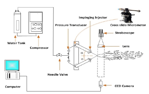
The experimental setup for our experiment is been illustrated schematically in Figure 1.The experimental system is composed of an impinging jet systems and the pressurized water tank compressed by air supply which on operation results the liquid sheet and the atomization. As illustrated in schematic, the pressurized water from the tank passes through the flow control valve and gets divides into two identical branches and passes through the pressure transducer and goes through the two individual impinging injectors.
The two individual impinging injectors were designed with an orifice diameter of 1.2 mm. The experimental impinging injectors were mounted on the coplanar and linear profile with the objectives of fine adjustments such that the distance of separation between two injectors tip, impingements angles as well as the pre-impingement length can be varied easily can be maintained constant on requirements. Both of the injectors are assembled such that they operate in similar physical condition of pressure and temperature and also act as a like on like type of injectors.
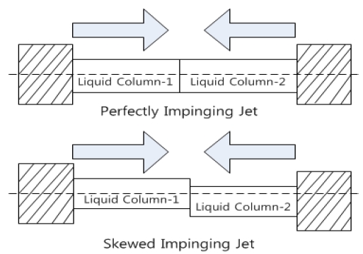
The angle of impingement of spray in the system can be adjusted by sliding the injectors around the micrometer as per the requirement. The pressure across each injector was measured by pressure transducer with an accuracy of 1% connected just ahead of injectors The fraction of skewness (SF) defined as the ratio of the offset between the axis of the jets to the diameter of the jets, as in Figure 2 of one injector with another was achieved by moving one of the jet injector with respect to another in precise fraction of millimeter. As our injectors are mounted on a cross slide with a micrometer of list count of 0.01mm, this feature of our system helps us to shift the injector through the fractional distance of 0.5 mm for each complete rotation.
The experiment was started with the calibration of orifice followed by the image photography. The breakup pattern of spray was visualized using the shadowgraph technique using the CCD cameras, one parallel and perpendicular to the plane of injectors, and two stroboscopes were used as the light sources and plane convex lens was used as the screen of visualization. An average of 30 spray images wasanalyzed to observe the stationary condition of spray test.
The experiment was carried out for several conditions of angle of incidence, factor of skewness and several pressure conditions. Experiments for each case were repeated three times to check reliability and the data hence obtained were averaged. The results obtained from our study were finally compared with similar researches, and study performed for like on like impinging injectors by others scholars and conclusions were derived.
3. Experimental Condition
For our experiment purpose,water was used as a simulant, the angle of impingement (2Φ) considered were 40,60 and 90 degree, preimpingement length was 4.0 cm and the Reynolds condition was ranged from 9 x 10³ - 4.5 x10⁴ based on the orifice diameter. The fraction of skewness considered for our experiment was ranged from 0.0-0.90 with the increment of 0.5 per steps. The coefficient of discharge for each injector was in the range of 0.70-0.85.The experimental conditions for the experiment are listed in Table1.
4. Results and Discussion
The following sub-sections illustrate the details of the results of study carried out for an impinging injector with the variancein fraction of skewness at different condition of pressure and impinging angle
4.1 Spray Structure
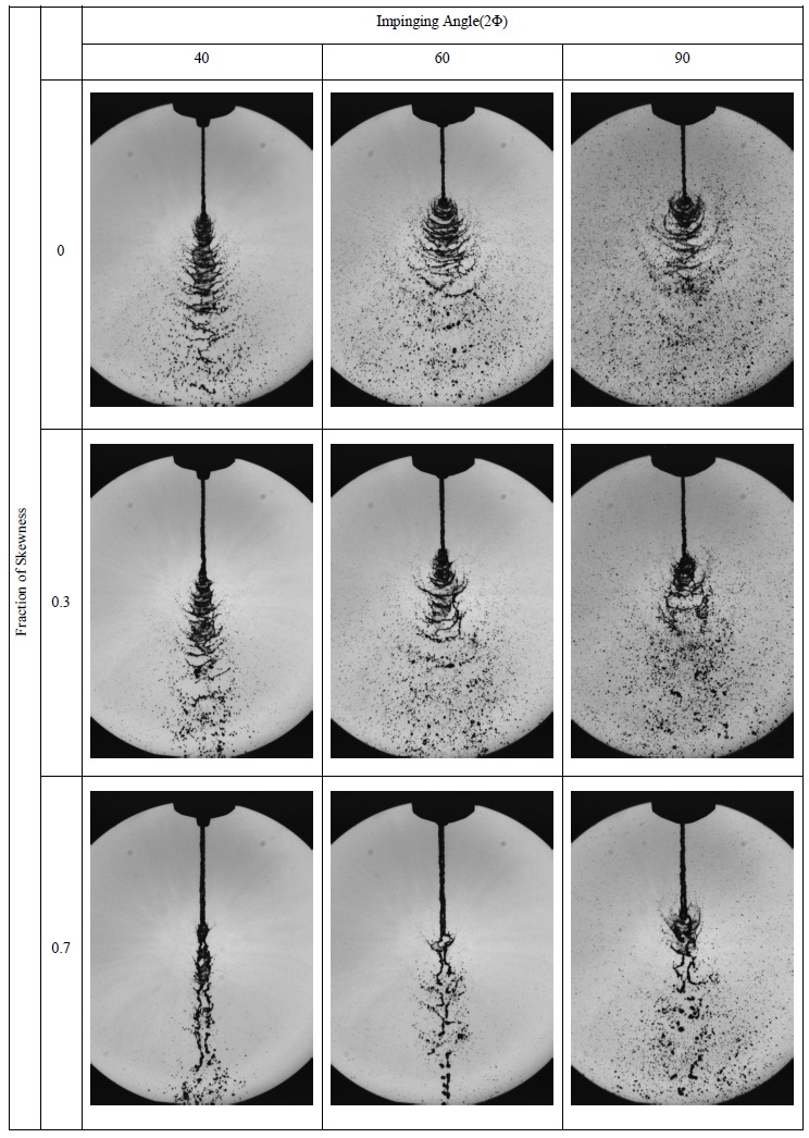
To study the impact of skewness in an atomization and combustion properties of an impinging injector, a spray test was conducted. The simulant delivered and projected from an orifice promptly stretches forward and forms a thin sheet laterally in a direction perpendicular to the plane of impinging jets. The breakup pattern of spray was then visualized and captured using the shadowgraph technique with the CCD cameras equipped with the lens of 18X, where CCD was installed such that one parallel and perpendicular to the plane of injectors, and two stroboscopes were used as the light sources and plane convex lens was used as the screen of visualization. An average of 30 spray images was analyzed to observe the stationary and stabilized condition of spray jets. The spray image hence captured were generally features an inertial jet core and the thin liquid sheet as the surrounding. For our study, the fraction of skewness (SF) defined as the ratio of the offset between the axis of the jets to the diameter of the jets is specified underneath of every individual images and was varied within the range from 0.0-0.9 and angle of impingement (2Φ) was 400, 600and 900. The spray images photography in Figure 6 present a brief illustration of how the fraction of skewness alters the breakup phenomenon of an impinging jets.
4.1 Break up length
With the start of a spray test a flat sheet with a distinct rim separating in a stochastic manner is seen produced perpendicularly to the plane of impingement. With the increase in fraction of skewness from perfect impinging to partial impingement, flapping motion of the lower part of the sheet break up the rim. The rim goes on spreading for a while and after gets slimmer and sheet appears shorter. As it is cleared from the shadow graph images different breakup patterns of skewed impinging jets in accordance with variance in fraction of skewness can be noticed.
The variance of the breakup length with the variance in pressure and the fraction of skewness were calculated using the shadowgraph images from Figure 6 and calculated results were plotted as the graph in Figure 3. As it isdemonstrated clearly in Figure 3, for impinging angle of 400breakup length were noticed decreased when the fraction of skewness was up to the 0.5 and goes on increase hence onward., while breakup length was found decreased up to fraction of skewness of 0.1 and increasing hence onward for an impinging angle of 600. Comparatively for impinging angle of 900,variance of breakup lengthwas found comparatively constant smallerup to the 0.3 and was found increase hence onward.
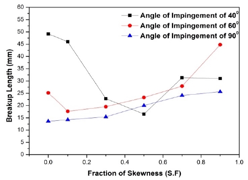
Variation of breakup length of skewed impinging injector with impinging angle of 400, 600 and 900 at pressure of 1bar
With the consequent increase of fraction of skewness, mode of sheet breakup changes by a Kelvin-Helmholtz-type instability, where ligaments seems separated rapidly and early, shortening the wave length. The mode of breakup is as similar to the ‘Ruffled Sheet Ligaments’ as described by Bailard et.al [6].
4.2 Angle of Spray
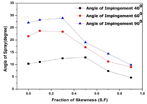
The variances of angle of spray with the variance in fraction of skewness were also calculated using the shadow graphic images in Figure 6 and results were demonstrated as Figure 4. The angle of spray was found increasing up to the skewness fraction of 0.3 for angle of impingement of 600and 900and goes on decreasing with the increased fraction of skewness, while angle of spray was found increasing up to the skewness fraction of 0.5 for angle of impingement of 400and goes on decreasing with increase in fraction of skewness. Illustrating the fact that there existcomparatively the lower provability of impingement of impinged solvent when with the fraction of skewness greater than 0.3.
4.3 Effect of Orifice Diameter
The variation of spray characteristics of skewed impinging injector with the discharge orifice diameter was studied by using gas jet orifice diameter of 1.5 mm and 1.2 mm. The atomization characteristics for same mass flow rate was found depended of orifice diameter. For water as simulant spray angle from both orifices at lo w liquid –air pressure were found comparatively similar possibly due to the dominant of prompt mode of atomization. As the larger orifice diameter case undergoes the classical mode of atomization, whereas the smaller orifice diameter undergoes the prompt mode of atomization with the increase in liquid pressure the smaller gas orifice results a higher spray angle. With the qualitative analysis of spray angle and penetrating distances, using smaller gas orifice has shown improved breakup for similar gas and liquid flow rates.
4.4 Effect of impinging angles
The comparative shadow graph images for the spray test with water as simulant is shown in Figure 6. As it is illustrated from the Figure 3 and Figure 4 significant alternation of the phenomenon was not clearly demonstrated but the atomization of spray was found better with the increasing in impinging angle with the shorter break up length and higher angle of spray and less alternation to the spray characteristics during the misalignment.
Figure 5, demonstrate the relationship between the angle of spray and the breakup length for the impinging angle of 900 for several fraction of skewness. When the factor of skewness was increased from zero i.e. from perfect impinging to partial impingement, increase in breakup length and decrease in spray angle was observed concluding that the maximum allowable fraction of misalignment for the impinging injectors in terms of fraction of skewness to be below the 0.3 for impinging angle of 900 and 600, and 0.5 for the impinging angle of 400as the spray characteristics are comparatively similar.
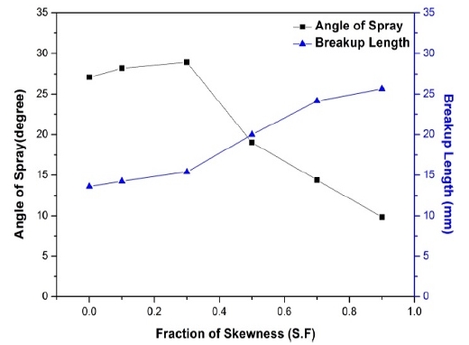
Variation of angle of sprayof skewed impinging injector with impinging angle of 900 at pressure of 1bar
5. Conclusions
The study of variation of atomization characteristics of an impinging injector with the factor of skewness was done and conclusion was derived. The maximum allowable skewnesswas found and the skewness was inversely proportional tothe angle of impingement. When the angle of impingement increased, the sensitivity of skewness decreased. In terms of spray performance, the skewness can be also used to predict the spray characteristics such as a breakup length and spray angle.
Acknowledgments
This work was supported by the SME Development Support Project (S2081919) through the Small and Medium Business Administration (SMBA).
This paper is extended and updated from the short version that appeared in the Proceedings of the International symposium on Marine Engineering and Technology (ISMT 2014), held at Paradise Hotel, Busan, Korea on September 17-19, 2014.
References
-
W. E. Anderson, H. M. Ryan, S. Pal, and R. J. Santoro, “Fundamental Studies of Impinging Liquid Jets”, Proceedings of the 30th Aerospace Sciences Meeting (AIAA-1992-0458), (1992).
[https://doi.org/10.2514/6.1992-458]

-
H. M. Ryan, W. E. Anderson, S. Pal, and R. J. Santoro, “Atomization characteristics of impinging liquid jets”, Journal of Propulsion and Power, 11(1), p135-144, (1995).
[https://doi.org/10.2514/3.23851]

- K. Jung, Y. Yoon, and S. S. Hwang, “Spray Characteristics of Impinging Jet InjectorsUsing Imaging Techniques”, Proceedings of the 36th AIAA/ASME/SAE/ASEE Joint Propulsion Conference & Exhibit (AIAA-2000-3396), (2000).
- M. F. Heidmann, R. J. Priem, J. C. Humphrey, A Study of Sprays Formed by Two Impinging Jets, NASA TN 3835, (1957).
-
H. P. Gadgil, and B.N. Raghunandan, “Effect of skewness on the characteristics of impinging jet atomizers”, Atomization and Sprays, 19(1), p1-18, (2009).
[https://doi.org/10.1615/AtomizSpr.v19.i1.10]

- G. Bailardi, M. Negri, and H. K. Ciezki, “Several aspects of the atomization behavior of various Newtonian fluids with a likeon-like impinging jet injector.”, Proceedings of the 23rd European Conference on Liquid Atomization and Spray Systems, (2010).

