
Influence on centrifugal force control in a self-driven oil purifier

Copyright © The Korean Society of Marine Engineering
This is an Open Access article distributed under the terms of the Creative Commons Attribution Non-Commercial License (http://creativecommons.org/licenses/by-nc/3.0), which permits unrestricted non-commercial use, distribution, and reproduction in any medium, provided the original work is properly cited.
The use of lubrication oil is of many purposes and one among them is to drive the engine mounted on a ship. Hence the supply of clean lubrication oil is important. And an oil purifier is one of key components in marine diesel engines. At present, the element type full-flow oil filter has been widely used for cleaning the engine oil. The self-driven centrifugal oil purifier is a device which is used to remove the impurities in lubrication oil using a jet flow. The flow characteristics and the physical behaviors of particles in this self-driven oil purifier were investigated numerically and the filtration efficiencies were evaluated. For calculations, a Computational Fluid Dynamics method is used and the Shear Stress Transport turbulence model has been adopted. The Multi Frames of Reference method is used to consider the rotating effect of the flows. The influence of centrifugal forcehas been numerically investigatedto improve filtration efficiency of tiny particles. As a result of this research, it was found that the particle filtration efficiency using the only center axis rotating and outer wall rotating system are higher than that of the fully rotating system in the self-driven oil purifier.
Keywords:
Self-driven oil purifier, Multi frames of reference, Filtration efficiency, Computational fluid dynamics1. Introduction
The extension of life expectancy of oil is of paramount importance due to rise in oil prices. As a result, the role of purifier is critical. An oil purifier is one of the key components in diesel engines. Generally, FO (Fuel Oil) purifier, LO (Lubrication Oil) purifier and system oil filter are widely used to maintain clean conditions of marine engines.
Figure 1 shows a schematic diagram of circulation system of lubrication oil. Most of the purifiers used for the full flow filter. This filter belongs to element types, and this kind of filters can't purify the sub-micron sized matters in the oil. In order to purify such matters the pore size should be reduced in the conventional filters. However, this produces large pressure drops, which eventually produces the oil circulations worse in the main lubricating lines. To solve this problem, a centrifugal oil purifier which takes about 10% of the total circulating oil from the main oil circulation system for purification is used

Sectional view of a self-driven type oil purifier
Several studies on the centrifugal type filters have been carried out. Jeong [1] carried out a study on the standard criteria of solid particle separation test for marine centrifugal purifier. Lee et al.[2] carried out a basic study on the integrated lubrication system for large scale marine diesel engine in terms of the lubrication efficiencies. Kim et al. [3] studied on the enhancements of filtration efficiencies of centrifugal purifiers in case of gas-liquid two phase flows. Bang et al. [4] evaluated the flow characteristics and the filtration efficiencies of a cylindrical centrifugal purifier for the case with simple inlet and outlet conditions. Smiles [5] investigated the centrifugal filtration of particulate systems by numerical analysis method. Most of the researches have focused on the cases having simple inlet and outlet conditions not considering actual conditions.
The purpose of this paper is to investigate flow characteristics and to enhance the filtration efficiency of tiny impurities. At the previous study, Jung and Pyo [6][7] investigated the filtration efficiency of centrifugal oil purifier about full rotating system which is rotating both axis and outer wall together. Figure 2 shows one of the previous results. In this figure, most of big impurities(over 50μm) are eliminated.

Filtration efficiency for the various condition at the result of previous study(effects of particle size and rotating speed)
But the filtration efficiencyof under 20μm is reported about 40 %.To improve this filtration efficiency of under 20μm, new ideas are needed. Why do we get poor efficiency in case of tiny particles? Many trial and errors make us think thoroughly the reason why small particles do not reach to the outer wall. The momentum for going to the outer wall decreases as the size of particles decreases. So, particles do not overcome the big pressure difference between the outer wall and axis and do not reach to the outer wall. This is the key reason. If we decrease the pressure gap between the outer wall and axis, we can get good efficiency for even tiny particles. We focus on the concept that centrifugal force induces the pressure difference between the outer wall and axis in rotating system. The new idea we adopted is to control the centrifugal force by changing the mechanism of rotating system.
To control the centrifugal force we adopted threemodels as shown in Figure 3, which are fully rotating system (case 1), outer wall rotating system (case 2) and axis rotating system (case 3). And we have investigated the effect of rotating speed(1800 rpm, 2700 rpm and 3600 rpm) for each case.

Threemodels ofrotating system to control centrifugal force
2. Numerical Analysis
Figure 4 shows the analysis domain of a centrifugal oil purifier. The oil comes in from the inlet at the upper part of the rotating shaft and it goes out through the outlet at the lower part. Generally, the oil inside the purifier is accelerated with the rotating wall and centrifugal force.The impurities in oilmove toward the outer wall of the rotating cylinder due to the inertia of their mass and are lastly accumulated at the outer wall of the purifier where a sheet of paper filter is installed. The centrifugal force is produced by the rotational moments which are generated by injecting oil via two nozzles installed oppositely at the lower part of the purifier as shown in Figure 1.

Analysis domain and boundary conditions for numerical simulation
Figure 5 shows the grid system for analysis. The tetrahedral meshes are used and the prism layer has been constructed at the wall side. The number of the grids is 700,000 cells.

Grid system forsimulation
The physical properties of the operating oil tested (SAE 30) are as follows;oil density ρ=853.9 kg/m^3, particle densityρ=6,000 kg/m^3and viscosity μ=0.00356 Pa∙s.
The SST (Shear Stress Transport) turbulence model is adopted due to its known superior standards and its reliability to model flows having higher shear stresses. To analysis the rotational effects of the flow fields, the function of MFR (Multi Frames of Reference) is applied and the equilibrium equation for the force acting on the particles is represented by the equation of a discrete particle traveling in a continuous fluid medium. This equation is derived by Basset, Boussinesq and Oseen for a rotating reference frame as follows;
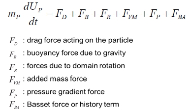
Where mp and up are mass of a particle and velocity of a particle respectively [8].
The inlet mass flow rate of oil is 0.92 kg/s and 1,000 particles are inserted into to evaluate filtration efficiency. And the coefficient of restitution of the outer wall is set to 0, which means that particles stick to the outer wall if particles reach to the outer wall. Pressure conditionis adopted as outlet boundary condition.
3. Result and Discussions
The filtration efficiency is defined by the ratio of the particle numbers filtrated over the total particle numbers inserted into the purifier. Accordingly, the filtration efficiency can be described as the following Equation (4).
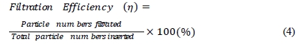
Figure 6 shows streamlines of the flow fields. At the case 1, the almost flow is gone to the outlet directly because of big pressure difference between the outer wall and axis as shown in Figure 8.Thebehavior of particles is influenced by flow pattern. So, case 1 represents low filtration efficiency regardless of three different rotating speeds. The flow pattern of case 2 and case 3 shows that the flow spreads out overall. The results show that case 2 and case 3 succeeded in reducing big pressure gaps by changing the rotating mechanism.

Flow patterns of three models with three RPMs
Figure 7 shows the particle behavior. At case 1, the pattern of particle behavior changeswith rotating speeds. Particles move widely with decreasing rotating speed. Because that centrifugal force decreases as rotating speed decreases. And it was confirmed that particles can move to the outer wall easily at case 2 and case3 due to small pressure gap between the outer wall and axis. But, in case of model 2, it should be pointed that particles stick to the narrow band.

Particle tracking forthree different rotating systemswith three rotating speeds
Figure 8 shows pressure distributions for the threemodels. It represents different distributionsquantitatively according to the types of rotating system. The pressure difference between the central axis and outer wall of Case 1 is about 400kPa. But the pressure differences of case 2 and case 3 are about 40kPa and 20kPa respectively. The pressure difference of case 1 is more10 times higher than case 2 and case 3. The pressure difference of case 1 is very big, so, it’s difficult that particles move to the outer wall. At the case 2, almost particles reach to the outer wall due tosmall pressure gapcomparing to case 1. The case 3 shows the smallest pressure gap. But it should bereminded that some particles of case 3 are rotating around outer wall as shown in Figure 7.

Pressure distributionsof threemodelswith 3600 rpm
Figure 9 represents thecomparison of filtration efficiency for the different three rotating systems and speeds. As we discussed above, relatively big particles (about 20-50μm) arehighly influenced by rotating speed. But,in case of tiny particles (4μm),it reveals that particles are not influenced by rotating speed comparing to big particles. Figure7 showthat the filtration efficiency can beimproved by controlling pressure difference caused by centrifugal force. And it was proven that case 2 and case 3 have good filtration efficiency as authors predicted theoretically.

Filtration efficiencyof threemodels
In this study, the effect of centrifugal force has been mainly investigated to improve the filtration efficiency of small particles. Because that centrifugal force in rotating fluid motion influences pressure difference as already known in fluid dynamics (F=ma normal to the streamline).
4. Conclusions
The characteristics of fluid flow and the physical behavior of the dust particles in various rotating conditions of the self-driven oil purifier have been numerically investigated by using CFD simulations to estimate the filtration efficiency. It was found that centrifugal force is the key factor to control pressure differences between the outer wall and center that hinder particle movement to the outer wall. And by investigating the filtration efficiency of three rotating systems (case 1: Fully rotating system, case 2: outer wall rotating system, case 3: axis rotating system),the filtration efficiency ofaxis rotating and outer wall rotating system is about 2 times higher than fully rotating system. It was also confirmed that the filtration efficiency increases as rotating speed increases.
The movement of particle is influenced by the fluid flow and internal distribution of pressure.
Acknowledgments
This research was financially supported by the ministry ofTrade, Industry and Energy (MOTIE) and Korea Institutefor Advancement of Technology (KIAT) through thePromoting Regional specialized Industry
This paper is extended and updated from the short version that appeared in the Proceedings of the International symposium on Marine Engineering and Technology (ISMT 2014), held at Paradise Hotel, Busan, Korea on September 17-19, 2014.
References
-
S. H. Jeong, “A study on the standard criteria of solid particle separation test for marine centrifugal purifier”, Journal of the Korean Society of Marine Engineering, 31(8), p1028-1034, (2007).
[https://doi.org/10.5916/jkosme.2007.31.8.1028]

- I. Y. Lee, and J. W. Kim, “A basic study on the integrated lubrication system for large scale marine diesel engines”, Proceeding of Spring Conference of the Korean Society for Power System Engineering, p262-266, (2003).
- J. M. Kim, J. H. Lee, Y. K. Yoon, and H. D. Kim, “A study of the performance improvement of a centrifugal separator for gasliquid two-phase flow”, Proceedings of the KSME 2007 Spring Annual Meeting, p3352-3357, (2007).
-
K. H. Bang, K. K. Kim, Y. A. Song, and P. S. Kim, “Numerical analysis of fluid flow and filtering efficiency in centrifugal oil filter”, Journal of the Korean Society of Marine Engineering, 33(6), p867-872, (2009).
[https://doi.org/10.5916/jkosme.2009.33.6.867]
-
D. E. Smiles, “Centrifugal filtration of particulate system”, Journal of Chemical Engineering Science, 54(2), p215-224, (1999).
[https://doi.org/10.1016/S0009-2509(98)00229-2]
-
H. Y. Jung, Y. H. Choi, Y. W. Lee, and D. H. Doh, “Numerical visualization of fluid flow and filtration efficiency in centrifugal oil purifier”, Journal of the Korean Society of Marine Engineering, 34(1), p84-91, (2010).
[https://doi.org/10.5916/jkosme.2010.34.1.084]
-
Y. S. Pyo, H. Y. Jung, Y. H. Choi, D. H. Doh, and Y. W. Lee, “Separation characteristics of particles in a self-rotating type centrifugal oil purifier”, Journal of the Korean Society of Marine Engineering, 38(2), p147-153, (2014).
[https://doi.org/10.5916/jkosme.2014.38.2.147]
- K. S. Hue, and S. Y. Seol, “Simulation of particle behavior in a swirl tube separator”, Proceedings of the KSME Spring Annual Meeting, p3051-3056, (2005).