
Numerical simulation of bubble growth and liquid flow in a bubble jet micro actuator

Copyright © The Korean Society of Marine Engineering
This is an Open Access article distributed under the terms of the Creative Commons Attribution Non-Commercial License (http://creativecommons.org/licenses/by-nc/3.0), which permits unrestricted non-commercial use, distribution, and reproduction in any medium, provided the original work is properly cited.
Numerical models of fluid dynamics inside the micro actuator chamber and nozzle are presented. The models include ink flow from reservoir, bubble formation and growth, ejection through the nozzle, and dynamics of refill process. Since high tapered nozzle is one of the very important parameters for overall actuator performance design. The effects of variations of nozzle thickness, diameter, and taper angles are simulated and some results are compared with the experimental results. It is found that the ink droplet ejection through the thinner and high tapered nozzle is more steady, fast, and robust.
Keywords:
Numerical smulation, Micro actuator; Bubble growth, Drop ejection, Volume of fluid1. Introduction
Thermal micro actuator, especially inkjet printhead has been researched and developed widely because of its high quality and low-cost printing ability [1]-[6]. In the thermal micro actuator, the explosive boiling generates high pressure to eject ink droplet through nozzles[5]. This superheat takes place on a thin layer of the heater inside the micro actuator head. This heating makes vapor bubbles on the heater.
A lot of small bubbles grow and form a big, high pressure bubble that transfers momentum to surrounding ink and ejects droplets. This bubble collapses after the ejection and ink refills inside chamber from the ink channel and reservoir [7]. Because of wetting problem on the surface of the nozzle, some anti-wetting materials need to be used for the final nozzle or nozzle surface finish.
Micro actuator nozzle can be made of metals like nickel and Stainless Steel (SS) or polyimide like Kapton-EⓇ and UpilexⓇ. Normally the thicknesses of micro actuator nozzles are 25–50 ㎛ and the diameters are 20–50 ㎛ depending on its purpose. Currently, a micro punching technique is used for SS nozzle and electro-forming is a standard fabrication process for the gold-coated – because of wetting problem - nickel nozzle.
In addition, the polyimide has better anti-wetting and anti-chemical characteristics. Because of natural characteristics of the excimer laser, we can expect some taper angles through the nozzle. Since the micro actuator holes have to work as real “nozzles”, some researchers tried to make high taper angle nozzles for high performance micro actuator [6].
In this paper, we will explain the basic design and function of polyimide nozzles and a three dimensional finite difference algorithm based on VOF method is used to predict the bubble behavior and the drop ejection in a micro actuator. The calculation results are compared with experimental data and the effect of nozzle dimension changes on the drop size and velocity is numerically investigated.
2. Principle of micro actuator
The substrates of thermal micro actuator heaters are fabricated using silicon wafers. This is done to take advantage of the tremendous material, process, and the equipment inventory built up by MEMS and because silicon is an excellent thermal conductor.
Figure 1 shows the droplet ejection form of commercial micro actuator (inkjet printhead). The Hp inkjet printhead is indicated in Figure 1 (a). This sketch is for an roof-shooter configuration. The Cannon’s inkjet printhead layout, however, is the edge-shooter, depicted in Figure 1 (b).

The commercial thermal micro actuator
For all thermal micro actuator (inkjet printhead), heater passivation, including the protection of leads, is critical to the service of the device. The violence of the bubble collapse and the chemical migration of atoms from the ink into the heater passivation materials are operational realities. They must be counteracted by exceptional materials innovation and attention to every design detail near the heater.
3. Designs for micro actuator nozzle
The design of micro actuator nozzle has been researched and developed because of its important role in overall micro actuator performance. It has been presented that the fluid ejection velocities, shapes of the fluid droplets, and formation and dynamics of satellites which can prevent high quality printing, are closely related to the characteristics of the raw materials, thickness, diameter and taper angle of the micro actuator nozzles [5].
Reducing the trials of the excimer laser micromachining of nozzles, numerical studies are carried out using a commercial software, Flow-3D. The drawing of the tapered nozzle is shown in Figure 2. The SEM photograph of one nozzle is shown in Figure 3. The nozzle plate thickness can be 25-50 ㎛, nozzle outlet diameters can be 20-50 ㎛, and taper angles can be 13–45°.

Designed polyimide nozzles

SEM photograph of one nozzle
Considering the micro actuator which is designed to eject 120-140 pico-liter (pl) through each nozzle (It is a huge volume for a droplet of inkjet printer), the nozzle diameter should be big (50–60μm) compared with the one designed to eject 30-50 pl. The nozzle material used here is polyimide film. The film thickness, nozzle diameter, taper angle, and shapes are to be determined from the design considerations with heater shape and overall performance. Most polyimide nozzles which are using in inkjet printers have 25-50 ㎛ thickness, 20-50 ㎛ outlet diameter, and 14-40° taper angles.
For our testing models, first of all, we started from the heater and chamber design. After we determined ink velocities, volumes, and firing frequencies, we made the numerical models and did a lot of parametric studies to find out optimal heater and chamber size, nozzle diameter, thickness, and taper angles. Based on numerical parametric studies, we could determine optimal parameters for all variables and excimer laser process.
4. Numerical simulation
When a short electrical pulse is applied to a thin film heater inside an micro actuator, fluid around the heater is superheated and the bubble nucleation is processed. The nucleated bubble is merging and expanded eventually ejected through the nozzles as droplets [6]. Figure 4 shows the bubble nucleation, growth and collapse process of micro actuator.

Bubble growth and collapse process
We made three-dimensional numerical models for our test model of micro actuator. The solver is used the Volume of Fluid (VOF) method of Flow-3D [8].
For the numerical model, it is necessary to calculate the temperature and pressure inside the bubble. One can calculate equilibrium vapor pressure as a function of temperature by integrating the Clausius-Clapeyron relation, resulting in the expression [2].
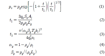
where pg, ρg, and Lg are vapor pressure, vapor density, and the heat of vaporization at the temperature Tg. al is the thermal diffusivity of the liquid and qh is the average heat flux from the heater to the liquid before the vapor film is formed. Also, Sh means the uniform heat flux area and kl is the heat conductivity of the liquid. Here, Al means the inertance of the liquid region, defined by,
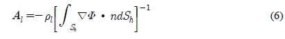
where n is the outward unit normal vector at the heating surface. Here Φ is the solution of the differential equation.
It is assumed that the temperature inside the bubble is uniform, and change of the bubble pressure follows Asai’s time profile.
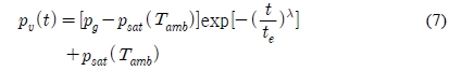
where Tamb is the ambient temperature, t is the time, pg is the pressure of bubble nucleation, psat is the saturation pressure, te is the time constant of pressure decrease, and λ is a parameter which depends on the thermal property of the fluid, heating condition, and magnitude of liquid inertance. It is also assumed that the initial bubble is formed around heater with 0.1-0.3 ㎛ thickness. The bubble grows from the initial stage, ejects the ink droplets and finally collapses inside the fluid chamber. The cold fluid fills up the chamber again while the bubble collapses.
A lot of numerical simulations are performed to find out optimal heater and chamber design. Using the results of this optimal heater and chamber design, we tried to find out the optimal nozzle thickness, diameter and taper angle. Figure 5 shows the geometry of test model.

Geometry of test model
5. Results and discussion
The numerical results of test model and the micrograph of inkjet droplet are shown in Figure 6. We can see the fluid firing of the test model at the time of 20 μs through 40 μs. The taper angle of this model is 14° and nozzle diameter and thickness are both 50 μm.

Fluid firing of test model
In this figure, two droplets are shown at the time of 20 μs and near 40 μs. The simulation result of drop velocity is 12.2 m/s and drop volume is 121.3 pico-liter (pl). On the other hand, the experimentally measured droplet velocity is about 12.0 ± 1.6 m/sec and volume is 122.3 ± 9.7 pl. It is found that the numerical results are well matched with the experimental results.
In Figure 7, we present the results of nozzle thickness changes. In this case, nozzle diameter is 50um and taper angle is 14°. According to nozzle thickness changes, the droplet velocity is increased 12.20m/sec to 13.24m/s and the droplet volume is changed 121.3 pico-liter (pl) to 124.5 pico-liter (pl).

Fluid droplet volume and velocity according to nozzle thickness
Following Figure 8 is the simulation result of the effects of the nozzle diameter changes. From the Figure 8, we can notice that the nozzle diameter increase can result droplet volume increase. However, the droplet velocity is not so much changed.
The calculating results of the effects of nozzle thickness and diameter changes are expressed in Table 1.

Fluid droplet volume and velocity according to nozzle diameter

Prediction results of the effects of nozzle thickness and diameter change
In Figure 9, the numerical results of fluid droplet velocity and volume changes according to nozzle taper angles of 14°, 30°, and 45° are shown. In addition, the experimental results of taper angles of 13.5° is presented for comparison. The velocity change is proportional to the taper angle change of the nozzle. The volumes do not change while the taper angle is increased. The amount of firing ink volume is actually more related to the size of chamber and operating frequency.

Fluid droplet volume and velocity according to nozzle taper angle
In Figure 10, the simulation results of the fluid droplet distance versus time according to nozzle taper angle is shown. We find that the slight nozzle taper angle increase results slight droplet distance increase. Table 2 shows the calculating results of the effects of nozzle taper angle.

Fluid droplet distance versus time according to nozzle taper angle
Prediction results of the effects of nozzle taper angle
Comparing each result in the figures, we conclude that the high tapered nozzle shows faster droplet velocity and almost same ink volumes. Although the velocity is not the only factor which can improve the printing quality of an inkjet printer, a faster droplet generally means less satellites, better anti-wetting condition, more effective alignment, and straight ejection
Comparing the results of the nozzle thickness changes, we find that thinner nozzle makes faster droplets.
6. Conclusions
The numerical simulation is successfully applied to the prediction of the micro bubble growth and the drop ejection phenomena. Compare with the results of the nozzle thickness changes, we find that thinner nozzle makes faster droplets. Also, the nozzle diameter increase can result droplet volume increase. In this numerical investigation, when we increased 20% of nozzle diameter the droplet volume is increased by 49.3% and decreased 20% of nozzle thickness the droplet velocity is increased by about 8.5%.
According to prediction result of the nozzle taper angle changes, we conclude that the high tapered nozzle shows faster droplet velocity and almost same fluid volumes.
Although the droplet velocity is not the only factor which can improve the quality of an drop ejection, a faster droplet generally means less satellites, better anti-wetting condition, more effective alignment, and straight ejection.
References
- A. Asai, S. Hirasawa, and I. Endo, “Bubble generation mechanism in the bubble jet recording process”, Journal of Imaging Technology, 14, p120-123, (1988).
-
A. Asai, “Bubble dynamics in boiling under high heat flux pulse heating”, Journal of Heat Transfer, 113, p973-979, (1991).
[https://doi.org/10.1115/1.2911230]

-
A. Asai, “Three-dimensional calculation of bubble growth and drop ejection in a bubble jet printer”, Transactions of the American Society of Machnical Engineers, 114, p638-641, (1992).
[https://doi.org/10.1115/1.2910079]
- P. M. Burke, and T. L. Weber, “Particle tolerant architecture”, IS&T’s NIP 16 International Conference on Digital Printing Technology, p39-43, (2000).
- N. Maluf, An Introduction to Micro Electro- mechanical Systems Engineering, Norwood: Artech House, p97-98, (2000).
- S. F. Pond, “Inkjet technology and product development strategies”, Carlsbad: Torrey Pines Research, p115-117, (2000).
- P. O. Michael, V. D. Narayan, J. D. Donald, “Drop Generation Process in TIJ Printheads”, IS&T’s 10th International Congress on Advances in Non-Impact Printing Technologies, p169-171, (1994).
- Flow Science Inc., Flow-3D User’s Manual Version 7.7, Los Alamos: Flow Science Inc., (2000).