Numerical analysis results of the cathodic protection for the underground steel pipe by anode installation method
Copyright © The Korean Society of Marine Engineering
This is an Open Access article distributed under the terms of the Creative Commons Attribution Non-Commercial License (http://creativecommons.org/licenses/by-nc/3.0), which permits unrestricted non-commercial use, distribution, and reproduction in any medium, provided the original work is properly cited.
This study aims to find out the best anode location for buried pipelines. Numerical simulation program known as CATPRO (Elsyca, Belgium) were used for confirming the best location of anodes and the effects of impressed current cathodic protection system. Applied conditions for numerical simulation were similar to on-site environmental conditions for optimal application of cathodic protection system. Used criterion of cathodic protection was NACE SP 0169, which describes that minimum requirement for cathodic protection is -850mV vs. CSE. Various layouts for anodes’ installation were applied, which were distance between anodes, anode installation location, and applied current. The areas where cathodic protection potential was lower than -850mV vs. CSE was limited up to 50m from anode installation locations. It was founded numerical analysis obtain cost-effective and efficient cathodic protection methods before design and application the impressed cathodic protection system to on-site environment.
Keywords:
Cathodic protection, Potential, Anode arrangement, Pipeline1. Introduction
Corrosion has been issued for a long time to deteriorate the steel and other materials. Various factors such as chlorides have negative influences on the deterioration of steel structures [1].
A lot of buried steel pipelines and buried steel tanks are used throughout the world for transport and storage of water, gas, fuel oil, and other chemicals. Corrosion damage results in loss of product, contamination of soil, and accidents that cause loss of service life [2].
The underground environments have a lot of moisture contents, high dissolved salt concentration, and sometimes high acidity is expected to be the most corrosive. However, soils alone have been found to have little corrosive. After long times goes by, the residence water on the surface of the pipeline or tank will control the corrosion underground environment. In fact, high corrosion rate in soils of low dissolved oxygen content are appeared. The anaerobic sulfate-reducing bacteria induced corrosion is common residents, which is microbiologically influenced corrosion.
Diverse protection methods have been developed, which can be changing mechanical and material properties, chemical protection such as using chemical inhibitor, and electrochemical protection typically known as the cathodic protection [3]-[8]. Among these methods, the cathodic protection is the common prevention method and considered as one of the efficient ways for the protection of the corrosion. There have been proper applications around the world including the protection of corrosion in pipelines.
The cathodic protection can be divided into two categories, which are the sacrificial anode cathodic protection and the impressed current cathodic protection. The sacrificial anode cathodic protection system is normally used due to its’ simplicities such as easier maintenance and simple installation. However, since sacrificial anode cathodic protection system has limit of throwing power, the distance that cathodic protection current is arrived to achieve good cathodic protection effects on the structures; thus, this system is difficult to be used in high resistivity conditions such as dry soil, and concrete.
Therefore, an alternative way is using impressed current cathodic protection system. Although it has high in installation and maintenance cost as well as system complexity, high current can be supplied to the protected material. There are several applications of impressed current cathodic protection system for pipeline [9]-[15].
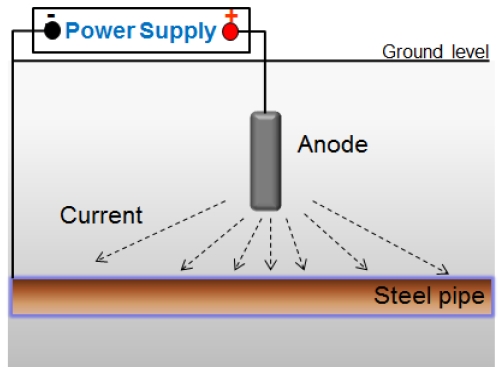
Figure 1 shows the schematic drawing of impressed current cathodic protection system in soil environment. A power supplies impressed current for cathodic polarization by converting alternating current to direct current and insoluble anode distribute the cathodic currents to the protected steel pipe structure, it may be high-silicone cast iron or platinum coated titanium. A steel pipe structure can be cathodically protected by connection to the negative pole of power supply unit.
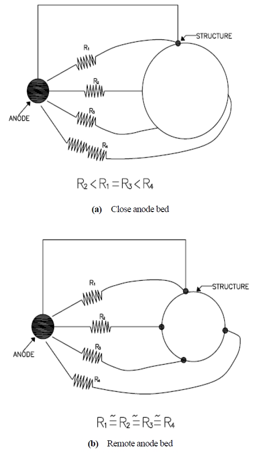
Figure 2 presents the schematic drawing of enhancing the importance of remote ground bed of insoluble anodes.
According to the ohm’s law, the protection current from the power supply unit by anode flows to the buried steel pipeline differently, and leads to the current distribution by the distance.
If the system keeps the distance sufficiently between the ground bed of the anode and the pipeline, it can be ensured to uniform current distribution and enlarge the protection range of the structure to solve this problem.
In this paper, therefore, influence factors in enhancing protection effects on the underground steel pipeline were introduced by using numerical simulation program, CATPRO (Elsyca, Belgium).
2. Experimental Methods
In order to find the best location for anode installation, numerical analysis program known as CATPRO (Elsyca, Belgium) was utilized, and impressed current cathodic protection system was used as a protection method. Used anode was Titanium coated by platinum with rod type. For practical on-site application, similar conditions were applied given in Table 1.
The basic dimension of pipeline was a length of 1km, an inner diameter of 1m, and pipeline thickness of 0.05m. Normal carbon steel called as SS400 was used in accordance with onsite applications. Used standard for the cathodic protection was NACE SP 0169 with maximum potential of -850 mV vs. copper/copper sulfate reference electrode (CSE) [16][17].
Various layouts for anodes’ installation were applied. Firstly, investigation related to the number of anode and the cathodic protection effects were carried out in case when anode and pipe was arranged with horizontally. With a distance of 5m between anode and pipe and applied current of 5A, comparison was conducted between at the center of pipeline (500m) with one anode and at the 300m, 500m, and 700m with three anodes. Secondly, in case when a distance of 5m between anode and pipe, the cathodic protection effects were analyzed between when one anode was installed at the center of pipe (500m) with applied current of 30A and three anodes were installed at pipe lengths of 498m, 500m, and 502m with applied current of 10A each.
In addition, the influence of distances between anodes on potential changes was confirmed. Specific experimental conditions for numerical analysis are given in Table 2.
3. Results
Figure 3 shows the cathodic protection effects of CASE 1. At the center of specimens (500m), the cathodic protection potential was the minimum value with -1,150mV vs. CSE, which satisfied the NACE SP 0169. Areas that satisfied NACE criterion was only up to 50mV away from location of anodes, which means that the potential of other 900m areas was higher than -850mV vs. CSE. Thus, it was not enough to install one anode at the center of pipeline in case when pipeline length is long.
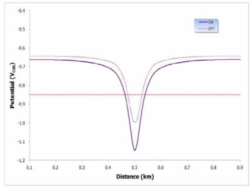
The cathodic protection potential of CASE 1 (Output current: 5A, the distance between pipeline and an anode installation location: 5m, resistivity: 8,000 Ω·cm)
Figure 4 presents the cathodic protection potential of CASE 2. Anode was horizontally arranged against pipe, and it is located at 300m, 500m, and 700m areas. The potential of location that anode was installed was -1,150mV vs. CSE, which was coincided with CASE 1. In addition, the areas where potential was lower than -850mV vs. CSE was limited up to 50m from anode installation locations.
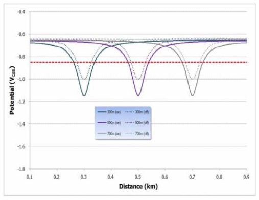
The cathodic protection potential of CASE 2 (Output current: 5A, the distance between pipeline and an anode installation location: 5m, resistivity: 8,000 Ω·cm)
Thus, the potential distribution of CASE 2 is exactly same as CASE 1. The areas where potential was lower than -850mV vs. CSE were proportionally increased with the number of anodes.
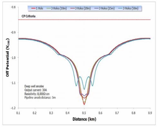
Figure 5 compares the cathodic protection potential result of CASE 3 and CASE 4. The off-potentials of CASE 3 and CASE 4 were same, which means that if the distance between anodes is close and the supplied current from three anodes is same as that from one anode, there is no difference between using three anodes with proximity and using one anode.
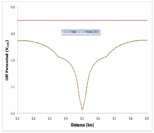
The cathodic protection potential of CASE 3 and CASE 4 (Output current: 30A vs. 10A+10A+10A, the distance between pipeline and anode installation location: 5m, resistivity: 8,000 Ω·cm)
Figure 6 presents the cathodic protection potential result of CASE 4, CASE 5, CASE 6, CASE 7, and CASE 8 related to the distance between anodes. As distance between anodes increased, the inclination of potential distribution was obvious. Large potential distribution could be confirmed as the distance between anodes increased. Compared to CASE 4, 5, 6, 7 and CASE 8 have a uniform potential distribution. It means that if we distribute the anode properly, uniform potential distribution can be confirmed.
4. Conclusions
This numerical analysis was conducted to obtain cost-effective and efficient cathodic protection methods, and following results have been obtained:
1) In case when one anode was installed at the center of the pipeline, the cathodic protection potential was -1,150mV vs. CSE. In addition, distance satisfying NACE cathodic protection criterion was 50m from anode. Thus, installing one anode at the center of pipeline is not a good solution.
2) In case of CASE 2, the potential of location that anode was installed was -1,150mV vs. CSE, which was coincided with CASE 1. In addition, the areas where potential was lower than -850mV vs. CSE was limited up to 50m from anode installation locations. Thus, if the supplied current as well as other environmental conditions are same, the minimum potential was always same in numerical analysis, which needs to be confirmed in the field experiment.
3) In case when the distance between anodes were close, distribution of cathodic protection was exactly same as when one anode was installed. From the numerical analysis results, distance between anodes should be longer than 25m to give uniform cathodic protection potential distribution.
This numerical analysis could show the basic trend of cathodic protection system. Specific field experimental should be provided to confirm the results of numerical analysis.
Acknowledgments
This paper is extended and updated from the short version that appeared in the Proceedings of the International symposium on Marine Engineering and Technology (ISMT 2014), held at Paradise Hotel, Busan, Korea on September 17-19, 2014.
References
-
C. Q. Li, and M. Mahmoodian, “Risk based service life prediction of underground cast iron pipes subjected to corrosion”, Journal of Reliability Engineering & System Safety, 119(13), p102-108, (2013).
[https://doi.org/10.1016/j.ress.2013.05.013]

-
W. Tian, N. Du, S. Li, S. Chen, and Q. Wu, “Metastable pitting corrosion of 304 stainless steel in 3.5% NaCl solution”, Journal of Corrosion Science, 85(41), p372-379, (2014).
[https://doi.org/10.1016/j.corsci.2014.04.033]

-
A. Bakkar, and S. Ataya, “Corrosion behaviour of stainless steel fibre-reinforced copper metal matrix composite with reference to electrochemical response of its constituents”, Journal of Corrosion Science, 85(38), p343-351, (2014).
[https://doi.org/10.1016/j.corsci.2014.04.037]

-
A. Ongun, Y. Basak, D. Mert, G. Kardas, and B. Yazici, “Electrochemical and quantum chemical studies of 2-amino-4-methyl-thiazole as corrosion inhibitor for mild steel in HCL solution”, Journal of Corrosion Science, 83(32), p310-316, (2014).
[https://doi.org/10.1016/j.corsci.2014.02.029]

- A. M. Al-Sabagh, N. G. Kandile, N. M. Nasser, M. R. Mishrif, and A. E. Ei-Tabey, “Novel surfactants incorporated with 1,3,5-triethanolhexahydro-1,3,5,-triazine moiety as corrosion inhibitors for carbon steel in hydrochloric acid : Electrochemical and quantum chemical investigations”, Egyptian Journal of Petroleum, 22(3), p351-365, (2013).
- D. A. Jones, Principles and Prevention of Corrosion, 2nd Edition, Upper Saddle River, New Jersey, the US: Prentice-Hall, (1996).
-
A. Conde, M. A. Arenas, and J. J. de Damborenea, “Electrodeposition of Zn-Ni coatings as Cd replacement for corrosion protection of high strength steel”, Journal of Corrosion Science, 53(4), p1489-1497, (2011).
[https://doi.org/10.1016/j.corsci.2011.01.021]

-
R. B. Polder, G. Leegwater, D. Worm, and W. Courage, “Service life and life cycle cost modelling of cathodic protection systems for concrete structures", Journal of Cement and Concrete Composites, 47(10), p69-74, (2014).
[https://doi.org/10.1016/j.cemconcomp.2013.05.004]

- E. Redaelli, F. Lollini, and L. Bertolini, “Throwing power of localized anodes for the cathodic protection of slender carbonated concrete elements in atmospheric conditions”, Journal of Construction and Building Materials, 39(15), p95-104, (2013).
- L. Bertolini, and E. Redaelli, “Throwing power of cathodic prevention applied by means of sacrificial anodes to partially submerged marine reinforced concrete piles : Results of numerical simulations”, Journal of Corrosion Sciences, 51(9), p2218-2230, (2009).
-
J. A. Jeong, and C. K. Jin, “Tidal water effect on the hybrid cathodic protection systems for marine concrete structures”, Journal of Advanced Concrete Technology, 10(12), p389-394, (2012).
[https://doi.org/10.3151/jact.10.389]

-
S. K. Jang, M. S. Han, and S. J. Kim, “Electrochemical characteristics of stainless steel using impressed current cathodic protection in seawater”, Journal of Transactions of Nonferrous Metal Society of China, 19(4), p930-934, (2009).
[https://doi.org/10.1016/S1003-6326(08)60380-5]

-
A. Yan, L. Feng, and Z. Wang, “Influence on yttrium addition on properties of Mg-based sacrificial anode”, ournal of Rare Earths, 28(1), p393-395, (2010).
[https://doi.org/10.1016/S1002-0721(10)60354-7]

-
J. A. Jeong, and C. K. Jin, “The effect of temperature and relative humidity on concrete slab specimens with impressed current cathodic protection system”, Journal of the Korean Society of Marine Engineering, 37(3), p260-265, (2013).
[https://doi.org/10.5916/jkosme.2013.37.3.260]

-
Y. B. Ko, G. B, Kim, and K. C. Park, “Soundness evaluation of friction stir welded A2024 alloy by non-destructive test”, Journal of the Korean Society of Marine Engineering, 37(2), p135-143, (2013), (in Korean).
[https://doi.org/10.5916/jkosme.2013.37.2.135]

-
J. H. Jeong, Y. H. Kim, K. M. Moon, M. H. Lee, and J. K. Kim, “Evaluation of the corrosion property on the welded zone of seawater pipe by A.C shielded metal arc welding”, Journal of theb Korean Society of Marine Engineering, 37(8), p877-885, (2013), (in Korean).
[https://doi.org/10.5916/jkosme.2013.37.8.877]

-
S. J. Kim, S. J. Lee, and S. O. Chong, “Effect of cavitation for electrochemical characteristics in seawater for austenitic 304 stainless steel”, Journal of the Korean Society of Marine Engineering, 37(5), p484-492, (2013), (in Korean).
[https://doi.org/10.5916/jkosme.2013.37.5.484]


