
Heat transfer enhancement of nanofluids in a pulsating heat pipe for heat dissipation of LED lighting

Copyright © The Korean Society of Marine Engineering
This is an Open Access article distributed under the terms of the Creative Commons Attribution Non-Commercial License (http://creativecommons.org/licenses/by-nc/3.0), which permits unrestricted non-commercial use, distribution, and reproduction in any medium, provided the original work is properly cited.
The effect of nanofluids on the heat transfer performance of a pulsating heat pipe has been experimentally investigated. Water-based diamond nanofluid and aluminium oxide (Al2O3) nanofluid were tested in the concentration range of 0.5-5%. The pulsating heat pipe was constructed using clear Pyrex tubes of 1.85 mm in inner diameter in order to visualize the pulsating action. The total number of turns was eight each for heated and cooled parts. The supply temperatures of heating water and cooling water were fixed at 80oC and 25oC respectively. The liquid charging ratio of the nanofluid was 50-70%. The test results showed that the case of 5% concentration of diamond nanofluid showed 18% increase in heat transfer rate compared to pure water. The case of 0.5% concentration of Al2O3 nanofluid showed 24% increase in heat transfer rate compared to pure water. But the increase of Al2O3 nanofluid concentration up to 3% did not show further enhancement in heat transfer. It is also observed that the deposited nanoparticles on the tube wall played a major role in enhanced evaporation of working fluid and this could be the reason for the enhancement of heat transfer by a nanofluid, not the enhanced thermal conductivity of the nanofluid.
Keywords:
Light emitting diode, Pulsating heat pipe, Nanofluid, Heat dissipation1. Introduction
Energy and environmental issues in the 21st century have prompted global interests in development of eco-friendly as well as higher efficiency energy systems. Among these, the LED (Light Emitting Diode) lamps have been replaced the conventional bulbs such as tungsten or fluorescent lamps. It has been known that the electrical power consumption of an LED lamp can be as low as one third of the tungsten bulb for the same luminance. Besides this advantage of low power consumption, the lifetime of an LED lamp could be infinite. But even by a practical estimate, it is much longer than that of conventional bulbs, typically more than 50000 hours.
One notes, however, that an LED lamp has not only such a great merit over the conventional lamps but also some technical issues that have to be overcome. One of them is heat dissipation technique. An LED is basically a semiconductor so that the allowed maximum operating temperature is as low as 100oC. Though the lower power consumption of an LED lamp is a great advantage, it is known that about 90 percents of the power consumed is still converted into heat [1] and this amount of heat must be properly dissipated in order for the temperature
of the LED module to be kept lower than the maximum allowed temperature.
For a high-power LED lamp, typically larger than 100 W, sufficient heat dissipation is essential to prolong the rated luminance and the lifetime. For those of water-proof or explosion-proof LED lamps, in particular, the LED electronic module must be physically isolated from the surrounding air, which is the ultimate heat sink for the heat produced in the LED module. In this case, an efficient heat transport path must be constructed between the inner electronic circuit of the lamp and the surrounding air.
For such a particular purpose, heat pipes are commonly used as an efficient and economical device. A typical heat pipe has so-called wicks on the inner surface of the heat pipe. The enlarged surface area by wicks provides large surface tension force that helps push back the condensed liquid at the cooled part to the heated part where the liquid evaporates again. The heat transport capability of this type of heat pipe is, therefore, largely dependent on the wick design. Another type of heat pipes is an oscillating heat pipe, or sometimes called a pulsating heat pipe, which has no wick, but plain surface of the heat pipe.
A pulsating heat pipe is an efficient heat transport device which employs evaporation of charged working fluid at the heat source and condensation at the heat sink of the heat pipe. The pressure difference between the evaporation and condensation parts acts to move the working fluid inside the heat pipe in an oscillatory pattern. A construction of multiple turns out of a long, capillary-size tube can amplify this pressure difference. Despite the advantages of simple and economical construction of a pulsating heat pipe, a practical application to cooling of electronic packages has been scarce. This is mainly because the pulsating action may not be sustained in some poor designs. It can be slowed down or seize sometimes.
In the past several decades, the experimental as well as theoretical studies on the pulsating heat pipe have been abundant since Akachi [2] patented it in 1990. The physical parameters that influence the operation and performance of the pulsating heat pipes are known to be tube diameter, thermal conditions (i.e., temperature range), type of working fluid, charging ratio, number of channels, and the arrangement (or inclination against gravity direction). Clear understanding and quantitative evaluation of the effect of these parameters on the PHP performance are crucial to the optimum design of the PHP for various application fields [3][4].
Kim et al. [5][6] conducted a series of experiments to investigate the effects of type of working fluid, charge ratio and the orientation of heat pipe on the heat transfer performance of a pulsating heat pipe. The fluids they tested were water, ethanol, acetone, R-123, and FC-72. Water was identified as the fluid that showed the best heat transfer performance. The best charge ratio, i.e., the ratio of charged liquid fluid volume to the total internal volume of heat pipe, was found to be near 50% regardless of the type of working fluid. It was also observed that for the orientation in which the heat pipe was vertically installed and the heating part was on the top and the cooling part was at the bottom, only R-123 was working properly. The number of turns of the pulsating heat pipe was also affecting the heat transfer performance; the more turns, the larger heat transfer.
In recent years, a nanofluid, which was first introduced by Choi [7], has drawn a great attention in the area of heat transfer augmentation technique. A nanofluid is a fluid containing nanometer-sized particles (1-100 nm), called nanoparticles. The nanoparticles are mixed with the base fluid in a form of colloidal suspension. Nanofluids generally show enhanced thermal conductivity and thus higher convective heat transfer coefficients compared to the base fluid. The nanoparticle materials of interest encompass metals and oxides such as silver, copper, Al2O3, CuO, SiO2, SiC, and recently grapheme oxide.
Ma et al. [8] first attempted to apply a nanofluid to a pulsating heat pipe to investigate the level of heat transfer enhancement by the nanofluid. They used diamond nanofluid (1% in volume) whose thermal conductivity was increased to 1.00 W/mK from 0.581 W/mK of pure water. The pulsating heat pipe was made of copper tube of 1.65 mm inner diameter. They observed the heat transfer performance was greatly enhanced by using this nanofluid. The thermal resistance across the heat pipe was reduced by 40%. It is noted, however, that their experiment was limited to heat flux boundary condition, i.e. they varied heat input to the heat pipe and measured the driving temperature difference. Since the heat transfer rate is proportional to the temperature difference, but also evaporation is dependent on the actual value of temperature of heated wall, the heat pipe performance is also affected by the temperature boundary condition.
In this study, the effect of nanofluids on the heat transfer performance of a pulsating heat pipe has been experimentally investigated. Waterbased diamond nanofluid and Al2O3 nanofluid were tested in the concentration range of 0.5-5%.
2. Experiment
2.1 Experimental Apparatus
The present experiment was designed to provide constant temperature boundary conditions to both heating and cooling sections by circulating water at a preset temperature through each water box in which the pulsating heat pipe was installed. Water box was made of polycarbonate plate for clear view. Penetrations of heat pipe through water box wall were sealed using adaptor and union tube fittings. A schematic diagram of the experimental apparatus is shown in Figure 1 and a photograph of the test section is given in Figure 2.

Schematic diagram of experimental apparatus

Photograph of experimental pulsating heat pipe
The pulsating heat pipe was constructed using clear Pyrex tubes in order to visualize the pulsating action. The inner diameter of the tube was 1.85 mm and the outer diameter was 3.0 mm. The total number of turns was eight each for heated and cooled parts. The maximum inner diameter of the tube for proper capillary force is given by [4],
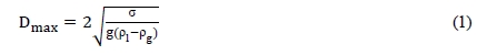
where σ is surface tension, ρl is liquid density, ρg is vapor density, and g is the gravitational acceleration. For water at 300 K, σ = 0.00717 N/m, ρl = 997 kg/m3, ρg = 25.6 kg/m3, thus Dmax = 1.74 mm. Based on this calculation, the inner diameter of the Pyrex tube is a little larger than this constraint, but it seems an acceptable size.
To obtain the heat transfer rate from the heating part to the cooling part, the flow rates of circulating water and the inlet and outlet water temperatures of each water box were measured. A rotameter was used for water flow rate measurement and it was calibrated in the laboratory to compensate the effect of water temperature. At the inlet of each water box, one thermocouple was installed to measure the supply water temperature. At the outlet of each water box, however, three thermocouples were installed with a proper spatial distribution to accurately measure bulk temperature at the exit. The temperature data were monitored using a Labview system and recorded at 60 Hz sampling rate.
2.2 Experimental Procedure
The major experimental parameters were the type of nanofluid, nanoparticle concentration, and the liquid charging ratio. For a test with the same nanofluid, the test heat pipe was reused for another concentration and charging ratio, but for a different nanofluid, a new heat pipe was replaced.
For every test run, the pulsating heat pipe was first vacuumed down to about 0.3 kPa using a vacuum pump. Then, the three-way ball valve was turned to charge a predetermined volume of liquid contained in a syringe which was connected to the ball valve. The valve was closed again. The valve connecting the two ends of the pulsating heat pipe was open for the open-type heat pipe or closed for the closed-type heat pipe. For most of runs in this study, the closed-type was chosen.
The heating water and the cooling water at a preset temperature were circulated through each water box. In this study, the heating part was the bottom section and the cooling part was the top section of the verticallyaligned pulsating heat pipe. As the water began circulation, the pulsating action started. It took some time, typically one or two hours, to reach a steady-state operation. Except when the video was taken for visualization purpose, the water boxes were insulated over the outside surfaces to minimize heat loss.
The heat transfer rate was calculated using the temperature rise of the cooling water since the heat loss in the cooling water box is negligibly small since the cooling water temperature was close to the ambient temperature. The heat balance across the cooling water box is given by,

The temperature data that were used for Equation (2) were sampled at several points during the period of steady state and were averaged value over 20 seconds at each point.
The measurement uncertainty was 0.1oC for the temperature difference, 3% for the flow rate. The cooling water circulation rate was 1 LPM and the lowest temperature rise in the cooling water box was 1.7oC. Thus, this lead to 6.6% of uncertainty in the heat transfer rate after the error propagation analysis.
3. Results and Discussions
3.1 Experimental Results
The experimental parameters were the type of nanofluid, nanoparticle concentration, and the liquid charging ratio. The nanofluids tested were water-based diamond nanofluid (NeoEnBiz Co.) and Al2O3 nanofluid (Aldrich Co.). The nanoparticle size and the thermal conductivity of these nanofluids are listed in Table 1. The supply temperatures of heating water and cooling water were fixed at 80oC and 25oC respectively. The water circulation rate was 1.0 LPM for both water boxes.

Nanoparticle size and thermal conductivity for 2% concentration in volume and 300 K
First, the pulsating heat pipe was charged with pure water for the base condition and the charging ratio was varied from 50% to 70%. The pulsating action as well as evaporation and condensation patterns were visualized through the transparent Pyrex tube, as shown in Figure 3. A long liquid slug and vapor slug were observed as expected. Pulsating characteristics and frequency are in the same trend as already reported in the previous study [5][6]. The heat transfer rate decreased as the charging ratio was increased as shown in Figure 4. The highest heat transfer rate was obtained at the charging ratio of 50%, and this result is consistent with the previous experimental study [5][6].

Long vapor and long liquid slugs observed through transparent Pyrex tube wall (Top: heating, Bottom: cooling)

Heat transfer rates of diamond nanofluid
Second, diamond nanofluid was tested for the nanoparticle concentrations of 1%, 3% and 5%. Diamond nanofluid was manufactured by NeoEnBiz Co. The charging ratio was also varied from 50% to 70%. The measured heat transfer rates are plotted in Figure 4. The case of 5% concentration of diamond nanofluid showed Figure 4. The case of 5% concentration of diamond nanofluid showed 18% increase in heat transfer rate compared to that of pure water.
After several runs with diamond nanofluid, it was clearly seen by bare eyes that the tube inner surface was coated with the nanoparticles. The nanoparticle coating certainly affects the evaporation at the heated wall. This will be discussed in more details later. For the tests with Al2O3 nanofluid, the Pyrex tubes were all replaced with a new set of tubes.
Al2O3 nanofluid was tested for the nanoparticle concentrations of 0.5%, 1% and 3%. The liquid charging ratio was 60% only in this case since the effect of liquid charging ratio has been fully investigated. The measured heat transfer rates are plotted in Figure 5. The case of 0.5% concentration of Al2O3 nanofluid showed 24% increase in heat transfer rate compared to that of pure water. The increase of Al2O3 nanofluid concentration up to 3% did not show further enhancement in heat transfer, as shown in Figure 5.

Heat transfer rates of Al2O3 nanofluid
One interesting observation through the clear Pyrex tube was that the nanoparticles were deposited on the inner tube wall, as noted already. This observation issued the effect of deposited nanoparticles. So, after empting the Al2O3 nanofluid, pure water was charged again and the ex periment was repeated. In this case, the heat transfer rate was about the same level of the cases with the nanofluid as shown in Figure 6. This implies that the evaporation of working fluid and this could be the reason for the enhancement of heat transfer by a nanofluid, not the enhanced thermal conductivity of the nanofluid.

Comparison of heat transfer rates
3.2 Remark on Heat Transfer Enhancement
The advantage of using a nanofluid is known enhanced thermal conductivity and thus enhancement of convective heat transfer coefficient. This is generally true for single phase convection where the heat transfer coefficient is directly proportional to thermal conductivity [7]. However, two-phase boiling heat transfer involves not only the convective evaporation at the liquid-vapor interface but also bubble nucleation and departure at the heated wall, called nucleate boiling. The size and frequency of bubble in nucleate boiling is strongly dependent on the heater surface conditions.
Coating or more generally surface modification by nanoparticles can greatly alter nucleate boiling characteristics. The deposition of nanoparticles on the heated wall provides increased number of smaller nucleation sites thus enhance evaporation rate.
The two-phase flow boiling heat transfer coefficient can be written in two contributions, namely nucleate boiling and convective boiling [9]

where F is enhancement factor for convection and S is suppression factor for nucleate boiling. The mass flux in pulsating heat pipe is usually small, thus nucleate boiling can be dominant. The nucleate boiling correlation proposed by Forster and Zuber [9] indicates the following proportionality between the heat transfer coefficient and the nucleation cite radius.

Here, r is the radius of nucleation site. Since the deposition of nanoparticles serves smaller nucleation site than that of bare surface, the nucleate boiling heat transfer coefficient increases. The quantitative evaluation of this enhancement requires the information on the size distribution of nucleation sites formed by the nanoparticle coating. This needs further study on the surface morphology.

Photograph of Al2O3 nanoparticles coated on the inner surface of Pyrex heat pipe.
4. Conclusions
The effect of nanofluids on the heat transfer performance of a pulsating heat pipe has been experimentally investigated. Water-based diamond nanofluid and Al2O3 nanofluid were tested in the concentration range of 0.5-5%. The liquid charging ratio of the nanofluid was 50-70%. The test results showed that the case of 5% concentration of diamond nanofluid showed 18% increase in heat transfer rate compared to pure water. The case of 0.5% concentration of Al2O3 nanofluid showed 24% increase in heat transfer rate compared to pure water, but the increase of Al2O3 nanofluid concentration up to 3% did not show further enhancement in heat transfer.
It is also observed that the deposited nanoparticles on the tube wall played a major role in enhanced evaporation of working fluid and this could be the reason for the enhancement of heat transfer by a nanofluid, not the enhanced thermal conductivity of the nanofluid.
Acknowledgments
This research was supported by the MSIP (The Ministry of Science, ICT and Future Planning), Korea, under the ITRC (Information Technology Research Center) support program supervised by the NIPA (National IT Industry Promotion Agency (NIPA-2013-H0301-13-2009)
This paper is extended and updated from the short version that appeared in the Proceedings of the International symposium on Marine Engineering and Technology (ISMT 2014), held at Paradise Hotel, Busan, Korea on September 17-19, 2014.
References
- M. H. Shin, “State of the art on a large output of power LED packaging”, Physics & High Technology, Korea Physical Society, 17(1), p16-21, (2008).
- H. Akachi, “Structure of a Heat Pipe”, U.S. Patent no. 4921041, (1990).
- J. S. Kim, N. H. Bui, J. W. Kim, J. H. Kim, and H. S. Jung, “Flow visualization of oscillation characteristics of liquid and vapor flow in the oscillation capillary tube heat pipe”, International Journal of Korean Society of Mechanical Engineers, 17(10), p1507-1519, (2003).
-
H. Yang, S. Khandekar, and M. Groll, “Operational limit of closed loop pulsating heat pipes”, Applied Thermal Engineering, 28, p49-59, (2008).
[https://doi.org/10.1016/j.applthermaleng.2007.01.033]

- H. T. Kim, A Study on Cooling of Flameproof LED Lightings using Pulsating Heat Pipes, M.S. Thesis, Korea Maritime University, (2012).
-
H. T. Kim, H. K. Park, and K. H. Bang, “Heat dissipation of sealed LED light fixtures using pulsating heat pipe technology”, Journal of the Korea Society of Marine Engineering, 36(1), p64-71, (2012).
[https://doi.org/10.5916/jkosme.2012.36.1.64]
- S. K. Das, S. U. S. Choi, W. Yu, and T. Pradeep, Nanofluids Science and Technology, Wiley, (2008).
- H. B. Ma, C. Wilson, B. Borgmeyer, K. Park, Q. Yu, S. U. S. Choi, and M. Tirumala, “Effect of nanofluid on the heat transport capability in an oscillating heat pipe”, Applied Physics Letter, 88(143116), p1-3, (2006).
- J. G. Collier, and J. R. Thome, Thome, Convective Boiling and Condensation, 3rd ed, Oxford, (1994).