Autonomous surveillance maneuvers for marine vessels in specially designated waters with a focus on the consecutive port and starboard turning cases
Copyright ⓒ The Korean Society of Marine Engineering
This is an Open Access article distributed under the terms of the Creative Commons Attribution Non-Commercial License (http://creativecommons.org/licenses/by-nc/3.0), which permits unrestricted non-commercial use, distribution, and reproduction in any medium, provided the original work is properly cited.
Abstract
This paper deals with autonomous surveillance maneuvers for marine vessels in specially designated waters (SDW) where the Sewol ferry disaster occurred. This study considers consecutive port and starboard (STBD) turning cases under multisinusoidal disturbances. Quintic polynomial damping has been suggested for mathematical development. The results reveal that the error performance decreased compared to the existing dynamics, which have no higher nonlinear damping. Model-based path-following control synthesis and tracking performances on curved routes are presented. Subsequently, an adaptive backstepping method is implemented to solve the nonintegrable constraints on accelerations in nonholonomic systems. The sway dynamics in an underactuated ship model are constructed using passive-boundedness, because sway control cannot be performed independently, whereas the other two motions (surge and yaw) are controlled independently. The closed stability of the controlled vessel system is guaranteed by Lyapunov theory. Finally, when a coast guard boat scans the entire area consistently, it may help decrease marine accidents in the SDW.
Keywords:
Specially designated waters (SDW), Underactuated, Error dynamics, Quintic polynomial damping, Surveillance routes, Disturbances1. Introduction
The International Convention on Maritime Search and Rescue (SAR) specifies best practices with regard to maneuvers in search and rescue areas rather than limited zones based on the experiences of the parties to the convention. The Korea Coast Guard (KCG) has designated special surveillance zones in coastal waters to prevent marine accidents, such as capsizing, collisions, and stranding. Even though the KCG already set security zones, they added specially designated waters (SDW) near the Mokpo and Tong-Yeong coastal seas owing to the special considerations that need to be made in these coastal seas to achieve a quick response. The SDW contributes to preventing marine accidents, such as the Sewol ferry disaster, by providing cumulative information such as traffic volumes, weather conditions, and distribution of fishing grounds in the SDW.
Patrol ships are monitored for 24 h to preemptively detect and counteract marine accidents. However, surveillance activities in SDW are usually dependent on the subjective judgment of the captains based on their individual experiences rather than a systematic sailing route. The SDW was placed in the shade because it was an unpatrolled area. Therefore, this study suggests an effective surveillance route to scan the SDW near Mokpo using a coast guard patrol model.
Autonomous marine vessels are state-of-the-art vessels in the marine industry. They have the potential to redefine the roles of humans in the marine industry. Autonomous vehicles have also been introduced in the fields of automated subways, self-driving, intra-logistics, and automated guided vehicles on container terminals [1].
Path-following control is considered one of the essential skills for autonomous maneuvers of marine vessels. Motion control can be classified into setpoint stabilization, trajectory tracking, and path/target following [2][3][4]. Recently, Zheng [5] studied path-following control of marine vessels with error constraints based on a moving frame. Zhang et al. [6][7] investigated the path-following control of an underactuated ship by considering actuator saturation and unknown disturbances. They constructed the concepts of a logical virtual ship and an actual following ship using a neural network algorithm. However, many studies [6][7][8][9] started with the idea of the passive boundedness of sway motion in point-to-point navigation of underactuated ships [10].
“Underactuated” systems are very important in the motion control field, especially in marine surface vessels. An underactuated system of marine vessels has fewer actuators than generalized coordinates [11][12]. In general, 3 degrees-of-freedom (DOF) marine vessels have two actuators, such as a propeller for surge control and various types of rudders for yaw moment control, exclusive of the sway actuator. The sway motion cannot be controlled directly, whereas the other two motions (surge and yaw) are controlled independently. Therefore, sway control cannot be performed independently for surface ships.
The sway motion of an underactuated surface vessel is bounded when the other variables are bounded [10]. This is related to the hydrodynamic resistance in the turning cases. The underactuated system cannot be asymptotically stabilized by feedback control; furthermore, it is not solvable by feedback linearization [3][13]. In this study, adaptive backstepping based on the Lyapunov scheme for a strict feedback system is employed to solve the nonintegrable constraints on acceleration in nonholonomic systems [10].
The concept of error dynamics also plays an important role in path-following control schemes. Based on the error dynamics, backstepping control is defined to converge the error variables (surge, sway, and yaw motions) to an invariant set. In addition, the hydrodynamic resistance in clam water consists of frictional, wave-making, and eddy resistances. These effects are represented in the form of nonlinearity [14], ignoring higher nonlinear damping terms.
For reference, marine vessels in calm water represent the sway force per yaw moment (equal to the sway/yaw added mass, m23) in turning cases. However, it is time-consuming to obtain off-diagonal elements from experiments and theory. In addition, the off-diagonal elements of a positive inertia matrix are significantly smaller than their diagonal counterparts [12]. Thus, a nondiagonal matrix, including m23, is not considered. Moreover, it does not consider the restoring force term.
This study implements model-based path-following control under multi-sinusoidal disturbances in the directions of surge, sway, and yaw. This study is based on a previous numerical approach [15] for the mathematical development of a ship model and control scheme, instead of an experimental study in an ocean environment. To solve the differential problem in the case of consecutive port and starboard (STBD) turning cases during a sufficient calculation, this study deals with consecutive port and STBD turning with a sufficient sailing time. It may overcome simple routes, such as straight-line, single-port, or STBD turning, for fast convergence and robust stability. Above all, this study reveals that the inclusion of quintic polynomial damping in a mass-damping system improves the error performance of a specific 3DOF ship model. This is the main difference between this study and the existing literature [6]-[10] that does not consider higher nonlinear damping terms.
The remainder of this paper is organized as follows. Section 2 introduces the mathematical formulation of the 3DOF model and the control synthesis. In Section 3, numerical simulations are performed to verify the control scheme. Finally, conclusions are presented in Section 4.
2.Mathematical Formulation
2.1 Underactuated 3DOF ship model
In this section, we organize the mathematical modeling for autonomous surveillance maneuvers based on an underactuated 3DOF model including surge, sway, and yaw motions. To improve error performance, we modify the damping terms in the vector representation. A well-known backstepping skill is considered to stabilize the error dynamics via virtual input. Then, an adaptive law treats both the unknown parameters and disturbances.
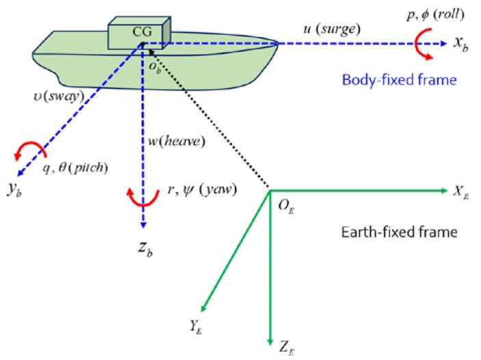
As shown in Figure 1, one can see two frames: body-fixed obxbybzb(moving coordinate) and earth-fixed OEXEYEZE.
The origin ob of the body-fixed frame is located at the center of gravity (CG). The body axes xb, yb, and zb are chosen to coincide with the principal axes of inertia eh [12]. The (x, y, z) and its time derivatives in the frame are equivalent to the position and translational movement, whereas (ϕ, θ, ψ) and their derivatives indicate the rotational change. No heave (w), pitch (q), or roll (p) are presented under the assumption that these motions are small.
Then, assuming that the marine vessels have a homogeneous mass distribution and symmetry in the xz-plane (port/STBD symmetry) such that Ixy = Iyz = 0 [12], the kinematics can be summarized as a mass-damper-spring system, as shown in Equations (1) and (2).
| (1) |
| (2) |
where η and ν are the orientation/position vector and linear/angular velocity vector, respectively; M denotes the system inertia matrix for kinetic rigid-body mass (Mb) and for hydrodynamic added mass (Ma); C is the Coriolis-centripetal matrix including the added mass; D is the linear viscous damping matrix generated by skin friction, wave drift, and vortex shedding; Dn(v) is the nonlinear damping matrix of quadratic and high-order; g(η) is the hydrostatic term of the gravitational forces and moments. It will be ignored in this study, however; and Aii (added mass) and Bii (linear frequency-dependent damping) are the potential coefficients (i = 1, 2, 6) at the center of flotation. The hydrodynamic terms can be computed based on the potential theory, where it is assumed that the flow is constant, irrotational, and incompressible; Tsurge, Tsway, and Tyaw are the time constants in the surge, sway, and yaw related to the linear viscous damping; τu and τr are the two actuators for surge and yaw; dwi(i = 1, 2, 3) is the environmental disturbance in the directions of the surge, sway, and yaw, sequentially [12], an underactuated 3DOF marine vessel can be rearranged as
| (3) |
| (4) |
where
m11=m-, m22=m-, m33=Iz-
Wu=[m22 / m11, du1 / m11, du2 / m11, du3 / m11, du4 / m11]
Wv=[m11 / m22, dv1 / m22, dv2 / m22, dv3 / m33, dv4 / m33]
Wr=[(m11-m22)/m33, dr1 / m33, dr2 / m33, dr3 / m33, dr4 / m33]
fu=[υr, -u, -u|u|, -u3, -u5]T
fv=[ur, -v, -v|v|, -v3, -v5]T
fr=[uυ, -r, -r|r|, -r3, -r5]T
where , , and are the known vectors; , , and represent the unknown vectors with the dimensions nu, nv, and nr ; du2, du3, du4, dv2, dv3, dv4, dr2, dr3, and dr4 denote the unknown nonlinear damping [3][7]. As stated in the Introduction, we suggest a novel damping-like quintic polynomial form. Thus, we can expect a better performance of the error dynamics.
Remark 1. There are various types of environmental disturbances acting on marine vessels, such as longitudinal/beam waves, winds, ocean currents, and hydrodynamic interaction forces between two marine vessels. See details in previous reports [16]–[21].
Assumption 1. The environmental disturbances can be observed in specially designated waters. However, the accurate amounts of disturbance are unknown and immeasurable. Thus, it is reasonable to assume that the time-varying disturbances dwi are bounded by the unknown constants dwu max, dwv max, and dwr max, that is, |dwu| ≤ dwu max, |dwv| ≤ dwv max, |dwr| ≤ dwr max [10].
Assumption 2. The sway velocity (v) is stable under passive boundedness. For the definition of the passive bound, see [10].
2.2 Control design
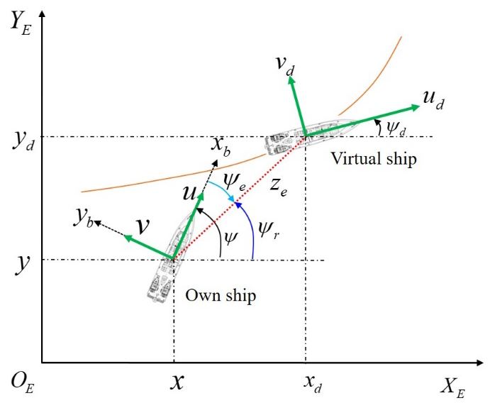
The basic framework of the control design is shown in Figure 2. One can see a virtual ship in front of it. The ideal (virtual) ship is defined as follows:
| (5) |
| (6) |
| (7) |
where xd, yd, ψd, ud, and rd are the desired positions, yaw angle, forward speed, and turning rate of the virtual ship, respectively. Sailing routes can be generated using rd .
Assumption 3. The surveillance routes are generated by virtual marine vessels that are similar to their own marine vessels, such that ηd = [xd, yd, ψd]T and its first/second derivatives , are all bounded [10].
As stated in [7][10], let the error variables be xe = xd - x, ye = yd - y , and ψe = ψr - ψ , the azimuth angle ψr(ψr ∈(−π,π]) of the ship can be defined as
| (8) |
where is the error in the diagonal line and sgn(⋅) denotes a sign function with sgn(0) = 1 .
Then, let the error variables be xe = zecos(ψr) and ye= zecos(ψr), and the derivatives of tracking errors ze and ψe are calculated as
| (9) |
| (10) |
To succeed in stabilization and tracking, backstepping can be designed recursively by applying the state variable as virtual control for surge ( αu ) and yaw ( αr ), as well as actual control inputs for surge ( τu ) and yaw ( τr ) are chosen as
| (11) |
| (12) |
| (13) |
| (14) |
where ku1, kr1, ku2, and kr2≥0 are the design parameters and zm is a positive value. The virtual ship is situated in front of the ship by ze-zm; The function ϑ(⋅) satisfies Lemma 1 [10].
Lemma 1. The δ > 0 , there exists a smooth function ϑ(⋅) , such that ϑ(0)=0
| (15) |
Remark 2. As stated in [10], ϑ(ς)=(1/4δ)ς satisfying Lemma 1 is used in this study.
Finally, the parameter updating law and estimated disturbances are given as
| (16) |
| (17) |
| (18) |
| (19) |
where is an estimate of Wi(i=u,r ); γwi1 ∈ ℜni×ni (i=u,r ) is the positive definite matrix; γwi2>0 , γdwi1 , γdwi2 ≥0 (i=u,r ) is the weighting factors; Wu0 , Wr0 , dwu max 0, and dwr max 0 are the initial design parameters [7][10].
Theorem 1. Consider a marine vessel in Equations (3) and (4) with Assumptions 1 to 3, the control law in Equations (13) and (14), and the adaptive law in Equations (16) to (19). All the signals in the closed-loop system are satisfied as being semiglobally uniformly ultimately bounded (SGUUB) [7].
Proof. See detailed in Appendix.
3. Simulation results
3.1 Surveillance routes and disturbances
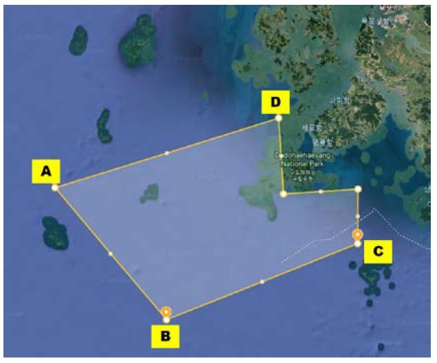
Figure 3 shows the specially designated waters (SDW) near Mokpo. After the Sewol ferry disaster occurred, the KCG established SDW near the Mokpo and Tong-Yeong coastal seas. In addition, the SAR convention already specified sufficient maneuvers in search and rescue areas rather than limited zones. The International Convention for the Safety of Life at Sea, 1974) specifies the practical and necessary arrangements for surveillance of search and rescue services considering the density of seagoing traffic and navigational dangers. However, environmental situations such as islands, wrecks, passing ships, and fishing distribution are not considered. This study focuses on surveillance routes consisting of consecutive ports and STBD turning cases with sufficient sailing times rather than traffic distribution.
| (20) |
As seen in Figure 3, the surveillance maneuvers will be done by zig-zag pattern (A-B-C-A-D-B-C-A points). First, the rate of turn (ROT, rd ) of the virtual ship generates the surveillance routes according to Equation (20). In order to understand the analysis of the results, we marked the turn numbers such as 1) to 8) in the turning states. It should be noted the proposed algorithm maintains the ship’s courses using ROT only, which is impractical for the current merchant ships depending on the rudder utilization.
where positive and negative values indicate predominant port and STBD turning, respectively. One can see the downsized sailing routes can be observed using Equation (20).
In addition, considering Remark 1 and Assumption 1, we assume that the environmental disturbances in the directions of surge, sway, and yaw are given as
| (21) |
Remark 3. The estimation of noisy sinusoidal signals is a significant problem for control system. It is known that the periodic disturbances can be expressed as the sum of bias (or offset), amplitude, frequency, and phase (or randomness). In practice, waves acting on marine vessels are nonstationary and unknown in advance. In particular, it is difficult to estimate the frequencies of unknown disturbances [22]. However, it is notable that the proposed control requires only boundaries of periodic disturbances, especially an upper bound. This study chooses the values in Equation (21) for a simple occurrence [23].
The initial conditions are [ x(0) , y(0) , ψ(0) , u(0) , v(0) , r(0) ] = [−50 m, 18 m, −0.15 rad, 0, 0, 0 rad/s]. The other parameters for the simulation are taken from [7][10]. The own ship is a patrol boat governed by Australian custom [1][15].
3.2 Results analysis
Autonomous surveillance maneuvers are performed within a sufficient time (1600 s). The consecutive port and STBD turning under severe disturbances may cause calculation problems in the underactuated system. In practice, officers on the bridge contemplate port turning in navigational situations such as head-on, crossing, and overtaking. In this simulation, we assume that there was no traffic distribution.
Table 1 shows the quantitative results of the maximum position errors (MPE) between surveillance routes (dashed blue) and trajectories (dashed red) during the port and STBD turning cases. From the initial position in Figure 4, own marine vessel navigates in the direction of the arrow until the vessel returns to the initial position. We numbered the each turning state in Equation (20). The MPE values in Table 1 were obtained using Equation (20). For example, a case of turn number 4) results in the two values such as 0.19 m for outer circle and 0.16 m for inner circle. The MPE of both port and STBD do not exceed 0.2 m in any turning situations. There are no significant differences between port and STBD turning maneuvers.
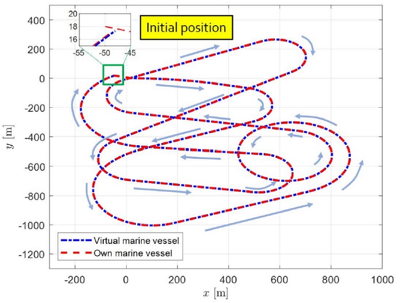
Path trajectories of a patrol boat (red line) and its virtual one (blue) including consecutive port and STBD turning
Figure 4 depicts the path trajectories of a patrol boat (red dash) and its virtual one (blue dash and dot) including consecutive port and STBD turning. In the figure, the surveillance course is represented by the blue dash and dot while the trajectories obtained by the proposed algorithm are represented by the red dash. Thus, the red line always should be situated on the blue line as long as possible, regardless of environmental disturbances. Starting from the initial position (A point) in Figure 3, the own marine vessel bound for the east will turn to STBD in the first turning state rd=−exp(0.005t/ 300) in 60 s, as seen in Equation (20). Then, a dubbin-type path can be seen from STBD turning (rd = −0.05 ), and the ship stays her course. The ROT remains zero so that the patrol boat can navigate southwest. After arriving near point, the vessel turns to the port (rd = 0.05t / 600 ) bound for the northeast. Likewise, the same step is performed until circular surveillance is carried out near point C. After surveillance from C to A, the vessel moves to point D. Similarly, consecutive STBD and port turning are performed until the marine vessel returns to its initial position.
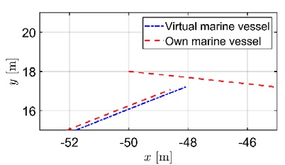
Figure 5 illustrates a magnification of a part of the return position. The return position error (RPE) is almost within 2 m of the final destination. In addition, the RPE are 0.15–0.2 m between the surveillance routes and actual trajectories.
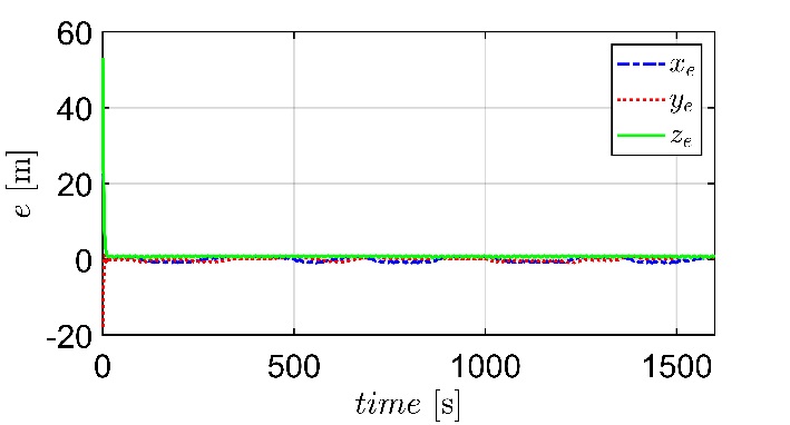
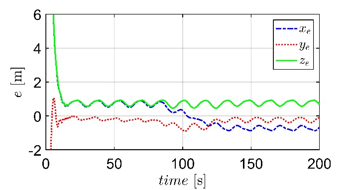
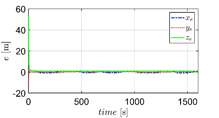
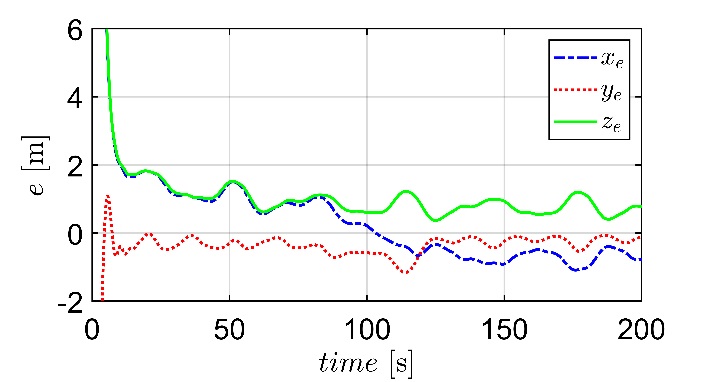
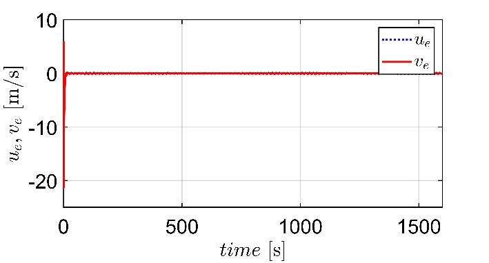
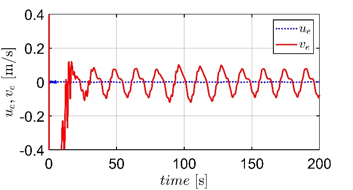
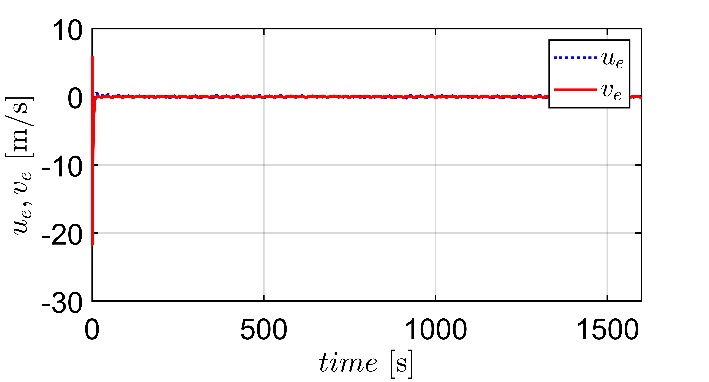
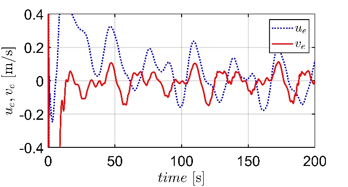
Contrary to Figure 4, the position ( xe, ye, ze ) and velocity errors ( ue, ve ) between one’s own vessel and the virtual vessel continue to fluctuate. This implies that the trajectories converge to an invariant set rather than an equilibrium. To analyze the performance of position and velocity errors, we compare the results of the proposed algorithm modified with quintic polynomial damping in Figures 6 and 7 for position errors and Figures 10 and 11 for velocity errors. The corresponding cases described in existing papers [6]-[10] without higher nonlinear damping are depicted in Figures 8, 9, 12, and 13. In addition, enlarged graphs such as Figures 7 and 11 for the current results by the authors and Figures 9 and 13 for the existing results by others [6]-[10] are presented. In addition to the transient state, the quantitative results of the position errors did not exceed 2 m in both the current and existing results.
For example, the maximum error of existing results in xe is 1.8 m in Figure 9 whereas the current result is 0.7–0.8 m in Figure 7 for steady-state responses. In particular, the improvement in error performance is dominant in ue by the suggestion of quintic polynomial damping. The surge velocity errors are suppressed in Figure 11, whereas the corresponding existing cases fluctuate, as shown in Figure 13. Overall, the application of quintic polynomial damping results in lower and periodic responses in the error performance.
Some error variables can be adjusted by changing the control parameters. The position errors reveal that the marine vessel follows behind the virtual vessel within 1 m despite multi-sinusoidal disturbances in the surge, sway, and yaw directions.
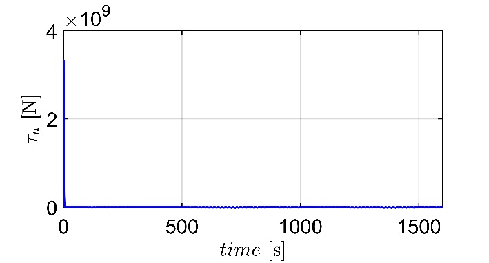
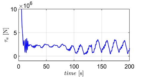
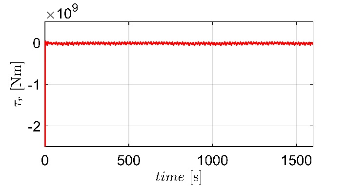
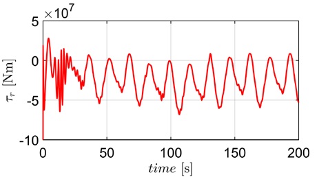
Then, the actual corresponding inputs for surge (τu) and yaw (τr) are shown in Figures 14 and 16. The enlarged graph at the start of control activation can be seen in Figures 15 and 17. This study improves the error performance in ue considerably. However, the high peak in surge control load in Figure 14 and its corresponding chattering in the transient state (see Figure 11) are somewhat disappointing because the path following control uses constant forward speed at start of simulation. This means that a careful trade-off is necessary to obtain a better performance and lower chattering. Otherwise, the sliding mode control with adaptive super-twisting is recommendable to treat such a problem [17][18]. Finally, it can be seen that the goals of consecutive port and STBD turning maneuvers depending on ROT are reached for autonomous surveillance of marine vessels in the SDW.
4. Conclusion
We analyzed consecutive port and STBD turning maneuvers of marine vessels for autonomous surveillance in the SDW where the Sewol ferry disaster occurred. First, a specific 3DOF ship model was formulated to improve the mathematical development for the application of a ship-handling simulator for education. A quintic polynomial damping term in the vector representation is suggested to improve error performance. In particular, the error of the surge dynamics almost reaches zero. However, the high peak in the surge control load and its corresponding chattering in the transient state remain unsatisfactory. Second, a model-based path-following scheme was summarized to achieve the goal of path tracking and sway boundedness for an underactuated system based on unknown nonlinear damping, which increases the resistance in turning maneuvers. Third, sufficient sailing routes for a patrol boat were presented to scan the SDW continuously, thus minimizing the unpatrolled area. Finally, the position and velocity errors demonstrate that the marine vessel follows the virtual vessel within 1 m, despite multi-sinusoidal disturbances in the surge, sway, and yaw directions.
Finally, the possibility of autonomous control in a real ocean under the same conditions as in this study is far from fully understood because the SDW is not a calm river. Thus, we should tackle the question “is it really controllable?” in future studies. In addition, the estimation of unknown disturbances is treated using adaptive backstepping control.
Author Contributions
Conceptualization, S. D. Lee; Methodology, S. D. Lee; Software, G. S. Jeong; Formal Analysis, S. D. Lee; Investigation, S, J. Lee; Resources, S, J. Lee; Data Curation, S, J. Lee; Writing-Original Draft Preparation, G. S. Jeong; Writing-Review & Editing, S. D. Lee; Visualization, S. D. Lee; Supervision, S. D. Lee.
References
-
S. D. Lee, X. Xu, H. S. Kim, and S. S. You, “Adaptive sliding mode control synthesis of maritime autonomous surface ship,” Journal of Korean Society of Marine Environment & Safety, vol. 25, no. 3, pp. 306-312, 2019.
[https://doi.org/10.7837/kosomes.2019.25.3.306]

-
Z. Zheng and L. Sun, “Path following control for marine surface vessel with uncertainties and input saturation,” Neurocomputing, vol. 177, no. 12, pp. 158-167, 2016.
[https://doi.org/10.1016/j.neucom.2015.11.017]

-
S. D. Lee, Y. S. Song, D. H. Kim, and M. R. Kang, “Path following control of an underactuated catamaran for recovery maneuvers,” Sensors, vol. 22, 2233, 2022.
[https://doi.org/10.3390/s22062233]

-
L. Liu, D. Wang, Z. Peng, C. L. Chen, and T. Li, “Bounded neural network control for target tracking of underactuated autonomous surface catamarans in the presence of uncertain target dynamics,” IEEE Transaction Neural Network Learning Systems, vol. 30, no. 4, pp. 1241-1249, 2018.
[https://doi.org/10.1109/TNNLS.2018.2868978]

-
Z. Zheng, “Moving path following control for a surface vessel with error constraint,” Automatica, vol. 118, 109040.
[https://doi.org/10.1016/j.automatica.2020.109040]

-
G. Zhang, C, Zhang, T. Yang, W. Zhang, “Disturbance observer-based composite neural learning path following control of underactuated ships subject to input saturation,” Ocean Engineering, vol. 216, 108033, 2020.
[https://doi.org/10.1016/j.oceaneng.2020.108033]

-
G. Zhang, X. Zhang, Y. Zheng, “Adaptive neural path-following control for underactuated ships in fields of marine practice,” Ocean Engineering, vol. 14, pp. 558-567, 2015.
[https://doi.org/10.1016/j.oceaneng.2015.05.013]

-
Z. Sun, G. Zhang, B. Yi, and W. Zhang, “Practical proportional integral sliding mode control for underactuated surface ships in the fields of marine practice,” Ocean Engineering, vol. 142, pp. 217-223, 2017.
[https://doi.org/10.1016/j.oceaneng.2017.07.010]

-
C. Zhang, G. Zhang, and X. Zhang, “DVSL guidance based composite neural path following control for underactuated cable-laying vessels using event-triggered inputs,” Ocean Engineering, vol. 238, 109713, 2021.
[https://doi.org/10.1016/j.oceaneng.2021.109713]

-
J. H. Lee, P. M. Lee, B. H. Jun, and Y. K. Lim, “Point-to-point navigation of underactuated ships,” Automatica, vol. 44, pp. 3201-3205, 2008.
[https://doi.org/10.1016/j.automatica.2008.08.003]

-
A. P. Aguiar and J. P. Hespanha, “Trajectory tracking and path following of underactuated autonomous vehicles with parametric modeling uncertainty,” IEEE Transactions on Automatic Control, vol. 52, no. 8, pp. 1362-1379, 2007.
[https://doi.org/10.1109/TAC.2007.902731]

-
T. I. Fossen, Handbook of Marine Craft Hydro Dynamics and Motion Control, 1st Edition, Hoboken, New Jersey, USA: John Wiley & Sons Ltd, 2011.
[https://doi.org/10.1002/9781119994138]

-
K. Y. Pettersen and T. I. Fossen, “Underactuated dynamic positioning of a ship—Experimental results,” IEEE Transaction Control Systems Technology, vol. 8, no. 5, pp. 863-891, 2000.
[https://doi.org/10.1109/87.865859]

- T. Perez and M. Blanke, “Mathematical ship modeling for control application,” Technical Report, pp. 1-22, 2002.
-
S. D. Lee, “Path-following control for autonomous navigation of marine vessels considering disturbances,” Journal of Korean Society of Marine Environment & Safety, vol. 27, no. 5, pp. 557-565, 2021.
[https://doi.org/10.7837/kosomes.2021.27.5.557]

-
S. D. Lee and S. S. You, “Dynamical analysis of the mooring vessel system under surge excitations,” Journal of Korean Society of Marine Environment & Safety, vol. 24, no. 2, pp. 140-145, 2018.
[https://doi.org/10.7837/kosomes.2018.24.2.140]

-
S. D. Lee, B. K. Lee, and S. S. You, “Sliding mode control with super-twisting algorithm for surge oscillation of mooring vessel system,” Journal of Korean Society of Marine Environment & Safety, vol. 24. no. 7, pp. 953-959, 2018.
[https://doi.org/10.7837/kosomes.2018.24.7.953]

-
S. D. Lee, B. D. H. Phuc, X. Xu, and S. S. You, “Roll suppression of marine vessels using adaptive super-twisting sliding mode control synthesis,” Ocean Engineering, vol. 195, 106724, 2020.
[https://doi.org/10.1016/j.oceaneng.2019.106724]

-
S. D. Lee and S. S. You, “Dynamical rolling analysis of a vessel in regular beam seas,” Journal of Korean Society of Marine Environment & Safety, vol. 24. no. 3, pp. 325-331, 2018.
[https://doi.org/10.7837/kosomes.2018.24.3.325]

-
S. D. Lee, S. S. You, X. Xu, and T. N. Cuong, “Active control synthesis of nonlinear pitch-roll motions for marine vessels,” Ocean Engineering, vol. 221, p 108537, 2021.
[https://doi.org/10.1016/j.oceaneng.2020.108537]

-
S. D. Lee, X. Xu, T. N. Cuong, and S. S. You, “Suppression of coupled pitch-roll motions using Quasi-sliding mode control,” Journal of Korean Society of Marine Environment & Safety, vol. 27. no. 2, pp. 211-218, 2021.
[https://doi.org/10.7837/kosomes.2021.27.2.211]

-
A. A. Pyrkin and S. A. Kolyubin, “Precise frequency estimator for noised periodical signals,” IEEE International Conference on Control Applications (CCA), October 3-5, Dubrovnik, Croatia, 2012.
[https://doi.org/10.1109/CCA.2012.6402392]

-
K. D. Do, Z. P. Jiang, and J. Pan, “Robust adaptive path following of underactuated ships,” Automatica, vol, 40, pp. 929-944, 2004.
[https://doi.org/10.1016/j.automatica.2004.01.021]

Appendix
Appendix
This section presents the stability analysis of the closed-loop system according to Theorem 1. The Lyapunov candidate is introduced as follows.
| (22) |
The derivative of V is given by
| (23) |
By substituting Equations (13), (14), and (16)–(19) into (23), we obtain
| (24) |
where
where , b1, Gi, a1, and b2 are positive constants. Then, by integrating Equation (24), we derive
| (25) |
V(t) is bounded satisfying . All the signals are guaranteed to be SGUUB [7].

