Energy-efficient simultaneous wireless information and power transfer-enabled orthogonal multiple access under distributed antenna systems
Copyright ⓒ The Korean Society of Marine Engineering
This is an Open Access article distributed under the terms of the Creative Commons Attribution Non-Commercial License (http://creativecommons.org/licenses/by-nc/3.0), which permits unrestricted non-commercial use, distribution, and reproduction in any medium, provided the original work is properly cited.
Abstract
The application of distributed antenna systems (DAS) to simultaneous wireless information and power transfer (SWIPT)-enabled orthogonal multiple access (OMA) systems is a potential solution for improving the energy efficiency (EE) of next-generation wireless networks, including wireless sensor networks of the Internet of Things (IoT). In this paper, we propose a framework for applying single-selection DAS to the SWIPT-enabled OMA system and analyze the synergetic effects of SWIPT and DAS collaboration. Moreover, we jointly optimize the power allocation for OMA signals and power splitting (PS) ratio assignments for SWIPT in the DAS to maximize EE while satisfying the minimum harvested energy and data rate constraints. However, the EE maximization problem is nonconvex; thus, it is challenging to find the optimal solution analytically. To resolve this difficulty, we divide the optimization problem into subproblems and apply an iterative algorithm to find the optimal solution. Numerical results validate the theoretical findings and demonstrate that the proposed framework using SWIPT-enabled OMA in DAS achieves a higher EE than the existing SWIPT-OMA and sum-rate-optimized SWIPT-OMA-DAS.
Keywords:
Energy efficiency (EE), Simultaneous wireless information and power transfer (SWIPT), Orthogonal multiple access (OMA), Distributed antenna system (DAS)1. Introduction
Future communication systems will lead to an increase in energy consumption owing to the development of the Internet of Things (IoT), which supports numerous wireless devices. This will cause a rapid increase in research focused on energy consumption [1]. In many IoT scenarios, charging a wireless-device battery over a wired connection incurs significant operating costs. As a method to solve this problem, radio frequency (RF) energy harvesting (EH) is garnering attention, which is one of the technologies for improving the energy efficiency (EE) of IoT [2].
Wireless power transfer (WPT) is regarded as a promising technology for efficiently managing battery charging problems through a reliable power supply [3]-[6]. Recently, simultaneous wireless information and power transfer (SWIPT), which simultaneously performs EH and information decoding (ID) from a single RF signal, has been studied as a future technology [7]. There are two types of SWIPT receiver structures: power splitting (PS) receivers and time switching (TS) receivers. The PS receiver divides the received signal into two streams by an appropriate ratio and uses them for EH and ID [8]. In contrast, the TS receiver performs EH and ID in different time slots [9]. Several studies have been performed under the assumption that SWIPT has a linear EH model. However, practical EH circuits typically exhibit nonlinear features owing to nonlinear components, such as diodes. Thus, the authors of [10] conducted a study on a nonlinear EH model for a more practical analysis.
However, SWIPT has a fatal disadvantage in that the energy transfer efficiency rapidly decreases with distance. A distributed antenna system (DAS) could be a solution to this transfer efficiency problem. In DAS, distributed antenna (DA) ports are geographically separated in the cell and connected to the base station (BS) via wired cables. DAS that are relatively close to celledge users can increase the throughput or reduce power consumption by cooperating with the BS [11]-[13]. Moreover, the authors of [14] proposed a method to maximize the EE of SWIPT through the application of DAS. Power allocation and PS control for the SWIPT-DAS system were optimized for composite fading channels [15] and imperfect channel state information (CSI) [16].
The contributions of this paper are as follows:
- · This paper proposes a framework for applying single-selection DAS to a SWIPT-enabled orthogonal multiple access (OMA) system and analyzing the synergetic effects of SWIPT and DAS collaboration. The DA ports can help the ID and EH for cell-edge users to improve their EE.
- · In terms of the EE, we jointly optimize the power allocation and PS control for the SWIPT-OMA signal when the DA port can support the cell-edge user. The optimization problem is divided into subproblems, and solutions of the subproblems can be found using a bisection method. Subsequently, an iterative algorithm is applied to find the joint optimal solution.
- · The simulation results demonstrate that the proposed method can improve the EE more than the sum-rate maximized SWIPT-OMA-DAS or SWIPT-OMA, while ensuring the minimum rate and harvested energy constraints.
2. System model
This section presents the system model of SWIPT-enabled OMA with DAS. We then derive the EE with respect to the allocated power and PS ratios.
2.1 Multi-cell distributed antenna systems
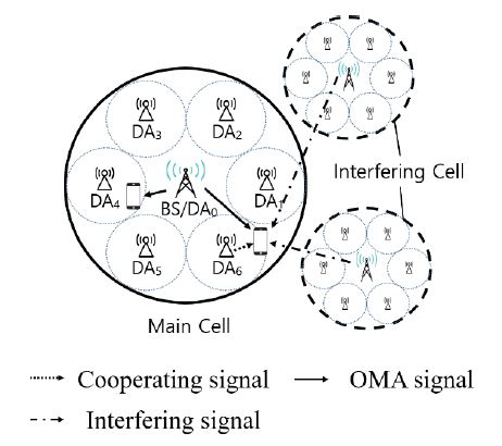
As shown in Figure 1, we consider a multi-cell DAS, where (N + 1) DA ports including BS. Each DA port and the user are equipped with a single antenna, and the BS and (N) DA ports are indexed by n = 0,1, . . . , N. DAs have their own coverage and serve users only within the coverage, whereas the BS can transmit signals to all users in the cell. L cells surround the main cell and interfere with the users of the main cell and are indexed as l = 1, . . . , L. The transmit powers of the BS and DA are denoted as PBS and PDA, respectively. The total transmit power in the cell is P = PBS + NPDA. In this study, we consider a two-user scenario, in which the cell-center user is referred to as user 1 and the cell-edge user is referred to as user 2.
2.2 Channel model
In this study, we assumed a Rayleigh fading channel. The channel coefficient from DA i in cell l to user j in the target cell is denoted as , where indicates the transmission distance; η denotes the path-loss exponent; and denotes the fast fading component with ~CN(0,1). For simplicity, we drop the target cell index; that is, . The BS uses the channel gain to determine users 1 and 2 to satisfy |h0,1|2 ≤ |h0,2|2.
2.3 Nonlinear energy harvesting (EH) model
In this subsection, the nonlinear EH model is introduced. The RF-to-DC power conversion function can be modelled as [17]
| (1) |
where Pin and M denote the input power and maximum harvested power at the receiver, respectively. The constants a and b are determined by the EH circuit properties.
2.4 SWIPT-enabled OMA in DAS
Let xi,j be the data symbol transmitted from DA i to user j, and assume . The received signals can then be expressed as
| (2) |
| (3) |
where vj and wj represent the inter-cell interference and additive white Gaussian noise (AWGN), with CN(0, ) at user j ∈ {1,2}, respectively. Here, the interference to user j ∈ {1,2} from the L interfering cells can be derived as
| (4) |
| (5) |
where represent the allocated power levels of the BS in interfering cell l, and denotes the allocated power of the DA in cell l. corresponds to a transmitted symbol from cell l. As it is based on a single selection DAS, only one DA indexed by nl in cell l interferes with the target cell. Each user uses a PS receiver, which divides the received signal by the ratio α ∈ [0,1] and 1 − α and uses them for ID and EH, respectively. The signal-to-interference-plus-noise ratio (SINR) can be derived as follows:
| (6) |
| (7) |
where denote the average powers of inter-cell interferences v1 and v2, respectively. These can be obtained as
| (8) |
| (9) |
As a result, the data rates achievable to users are given by
| (10) |
| (11) |
where γ ∈ (0,1) represents the portion used for user 1’s transmission in the total bandwidth B, whereas user 2 uses (1 − γ). Additionally, q1, q2, and r1 are defined as . Consequently, the sum-rate achieved by SWIPT-OMA in DAS is given by Rsum = R1 + R2. The harvested powers of users 1 and 2 are
| (12) |
| (13) |
The total power consumption of the system is defined as Ptotal = P1 + P2 + PDA + PC − E1 − E2 , where PC denotes the circuit power consumed by the system circuit. EE can be defined as the ratio of the sum-rate to the total power consumption. Therefore, the EE of the system can be written as
| (14) |
3. Energy efficiency maximizing power allocation and PS ratio assignment algorithm
This section optimizes the power allocation and PS ratio control to maximize the EE. Because PBS = P1 + P2, the EE maximization problem can be expressed as follows:
| (15) |
| (15a) |
| (15b) |
| (15c) |
| (15d) |
| (15e) |
| (15f) |
where denote the maximum transmit powers of the BS and DA, respectively. Rmin refers to the minimum rate constraint, and denotes the minimum harvested energy requirement for user j.
3.1 Outage condition
In this subsection, we discuss the outage conditions for problem (15). Using (10)-(13), constraints (15a) and (15b) can be reexpressed as follows:
| (16) |
| (17) |
Thus, the conditions for the feasible region to be a nonempty set are as follows:
| (18) |
| (19) |
| (20) |
| (21) |
where
| (22) |
| (23) |
| (24) |
| (25) |
| (26) |
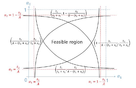
In Figure 2, the feasible regions of α1 and α2 are graphically represented. Equations (18)–(21) constitute the boundaries of the region. An outage event occurs when a feasible region does not exist. Using this, we can state the following lemma:
Lemma 1. The system becomes outage when the inequality t1 + t2 + s1 + s2 > Q holds.
Proof) As shown in Figure 2, the feasible region should satisfy to avoid an outage event. Combining the above equations, t1 + t2 + s1 + s2 ≤ Q. Therefore, the condition t1 + t2 + s1 + s2 > Q, causes an outage event.
3.2 Optimal power PS ratio control
In this subsection, we find that the optimal PS ratios maximizing the EE for a given power allocation of the BS and DA is fixed. The optimal values are obtained sequentially for the other.
First, we obtain the optimal PS ratio for user 1. For a fixed value of α2, α1 should satisfy
| (27) |
where . Accordingly, the derivative can be derived as
| (28) |
Here gα1(α1) is a decreasing function. Similarly, for a given α1, , and the constraint of α2 can also be derived as:
| (29) |
| (30) |
Where is also a decreasing function of α2. We can then find the optimal () by applying the bisection method, as summarized in Algorithm 1.
3.3 Optimal power allocation
In this subsection, the optimal power allocation that maximizes the EE is described for the given PS ratios α1 and α2.
First, we obtain the optimal power allocation of the BS, that is, . Similar to Subsection 3.1, , and the constraint of P1 can be derived as
| (31) |
| (32) |
where is a negative function of P1, the optimal for a given P2 can be obtained by applying the bisection method.
The optimal can be obtained in a similar manner. For a given P1, g2(P2) and the constraint of P2 are expressed as
| (33) |
| (34) |
where .
Thus, the optimal power allocation of BS, , can be obtained via an iterative algorithm in a manner similar to that of Algorithm 1.
Finally, we focus on finding the optimal power allocation of the DA for given P1, P2, α1, and α2. The derivative and the constraint of PDA are derived as
| (35) |
| (36) |
where . The optimal can also be obtained using the bisection method.
We now demonstrate the joint PS ratio control and power allocation, maximizing EE λ. In our design, we successively find the optimal power allocation and PS ratio when the other variables are fixed and apply an alternating algorithm to obtain a joint optimal solution. Algorithm 2 summarizes the overall algorithm for maximizing the EE of SWIPT-OMA in DAS. The proposed method does not ensure a global optimum because of the nonconvexity of the joint optimization problem but finds a local maximum. Therefore, we set Nt random initial points.
4. Numerical results
This section presents the numerical results of the proposed power allocation and PS ratio control for SWIPT-enabled OMA in DAS. We assume that the radii of the cell and local area of the DA are 20 m and 20/3 m, respectively. The bandwidth B = 5 MHz, γ = 0.5; noise variance = −90 dBm/Hz; minimum rate constraint Rmin = 0.4 bps/Hz; and circuit power PC = 1 W are used. Moreover, we assume N = 6; L = 6; Nt = 10 initial points; for the power budget, and = 10 mW for the minimum harvested energy requirement. For the nonlinear EH model, we use M = 24 mW; a = 150; and b = 0.014 [10]. For user locations, the cell-center user is uniformly distributed within a circle with a normalized cell radius of 0.3, and the cell-edge user is uniformly distributed within the area between the inner circle with a normalized cell radius of 0.7 and the outer circle with a normalized cell radius of 1.0. To verify the performance of the proposed method, it is compared with the following schemes.
- SWIPT-OMA: SWIPT is used, but DAS does not consider the OMA method. The BS has a power budget P and serves two users with appropriate power allocation.
- Rate-max SWIPT-OMA-DAS: This is a method of determining resource allocation to maximize the sum-rate rather than EE in the SWIPT-OMA-DAS environment. Therefore, in this method, both the BS and DA use the maximum transmit power; that is, .
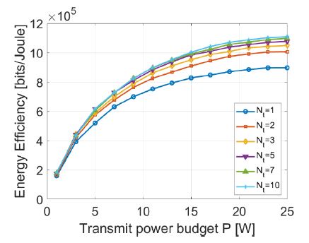
Figure 3 illustrates the impacts of the number of initial points, Nt, on EE performance. When there are more than seven initial points, the proposed method exhibits an almost converged performance, which is close to the global optimum. Therefore, we set Nt = 10 for the simulation.
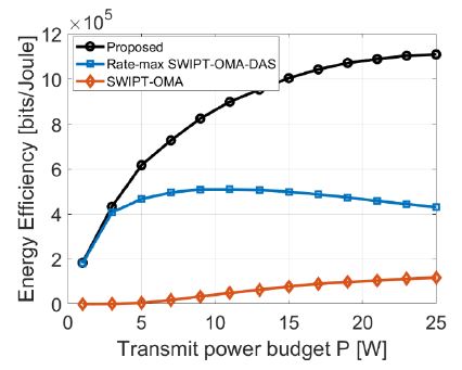
In Figure 4, an EE performance comparison for different power budgets is presented. It is evident that the proposed method outperforms the other methods in all ranges of P. This indicates that using DAS is beneficial in terms of EE. Because the proposed method and ‘SWIPT-OMA’ are methods for maximizing EE, the performance increases as P increases. However, the graph of ‘Rate-max SWIPT-OMA-DAS’ has a tendency to increase and then decrease. The power allocation and PS ratios of ‘Rate-max SWIPT-OMA-DAS’ are obtained to maximize the sum rate, which increases as P grows. This means that the gain in the acquired data rate decreases compared to the increase in power consumption.
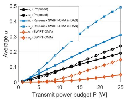
Figure 5 presents a comparison of the average PS ratio for different power budgets. In all the methods, the PS ratio of user 2, which has a relatively large channel gain, has a larger value than that of user 1. Here, α values of ‘Rate-max SWIPT-OMA-DAS’ are higher than those of the other schemes. This is because maximum power is devoted to the ID to maximize the sum-rate. In addition, it is evident that the proposed method has higher alpha than ‘SWIPT-OMA’ because DAS allows additional power to be invested in ID.
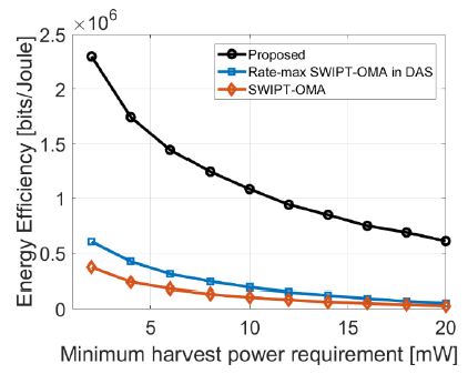
Figure 6 presents a performance comparison of the EE as the minimum harvested energy requirement, , when the power budget P = 20W. It is evident that the performance of the proposed method is superior to that of the other comparative methods. Because EH is performed more efficiently by applying DAS, it exhibits high performance even for large .
5. Conclusion
In this paper, we proposed an energy-efficient method for SWIPT-OMA-DAS under a nonlinear EH model. We found that applying DAS to the SWIPT-OMA system could greatly improve EH and energy efficiency. In the proposed system, the optimal power allocation and PS ratio control for maximizing the energy efficiency while satisfying both the minimum EH and data rate constraints were presented. The numerical results demonstrated that the energy efficiency of the SWIPT-OMA system was improved by applying DAS.
Acknowledgments
This research was supported by Basic Science Research Program through the National Research Foundation of Korea (NRF) funded by the Ministry of Education (2021R1A6A3A01087324, 2021R1I1A3044405).
Author Contributions
Conceptualization, D. Kim and D. -W. Seo; Methodology, D. Kim; Software, D. Kim; Validation, D. Kim and D. -W. Seo; Formal Analysis, D. Kim; Investigation, D. Kim; Resources, D. Kim; Data Curation, D. Kim; Writing—Original Draft Preparation, D. Kim; Writing—Review & Editing, D. -W. Seo; Visualization, D. Kim; Supervision, D. -W. Seo; Project Administration, D. -W. Seo; Funding Acquisition, D. Kim and D. -W. Seo.
References
-
A. Al-Fuqaha, M. Guizani, M. Mohammadi, M. Aledhari and M. Ayyash, “Internet of Things: A survey on enabling technologies, protocols, and applications,” IEEE Communications Surveys & Tutorials, vol. 17, no. 4, pp. 2347-2376, Fourthquarter 2015.
[https://doi.org/10.1109/COMST.2015.2444095]

-
P. Kamalinejad, C. Mahapatra, Z. Sheng, S. Mirabbasi, V. C. M. Leung, and Y. L. Guan, “Wireless energy harvesting for the Internet of Things,” IEEE Communications Magazine, vol. 53, no. 6, pp. 102–108, 2015.
[https://doi.org/10.1109/MCOM.2015.7120024]

-
D.-W. Seo, J.-H. Lee, and H. Lee, “Method for adjusting single matching network for high‐power transfer efficiency of wireless power transfer system,” ETRI Journal, vol. 38, no. 5, pp. 962-971, 2016.
[https://doi.org/10.4218/etrij.16.2615.0012]

-
D. -W. Seo, J. -H. Lee, and H. Lee, “Integration of resonant coil for wireless power transfer and implantable antenna for signal transfer,” International Journal of Antennas and Propagation, vol. 2016, Article ID 7101207, 2016.
[https://doi.org/10.1155/2016/7101207]

-
D. -W. Seo, S. -T. Khang, S. -C. Chae, J. -W. Yu, G. -K. Lee, and W. -S. Lee, “Open‐loop self‐adaptive wireless power transfer system for medical implants,” Microwave and Optical Technology Letters, vol. 58, no. 6, pp. 1271-1275, 2016.
[https://doi.org/10.1002/mop.29796]

-
J. -H. Lee and D. -W. Seo, “Development of an implant sensor capable of wireless charging: Electric circuit part,” Journal of the Korean Society of Marine Engineering, vol. 42, no. 6, pp. 478-484, 2018 (in Korean).
[https://doi.org/10.5916/jkosme.2018.42.6.478]

-
I. Krikidis, S. Timotheou, S. Nikolaou, G. Zheng, D. W. K. Ng, and R. Schober, “Simultaneous wireless information and power transfer in modern communication systems,” IEEE Communications Magazine, vol. 52, no. 11, pp. 104-110, 2014.
[https://doi.org/10.1109/MCOM.2014.6957150]

-
R. Zhang and C. K. Ho, “MIMO broadcasting for simultaneous wireless information and power transfer,” IEEE Transactions on Wireless Communications, vol. 12, no. 5, pp. 1989-2001, 2013.
[https://doi.org/10.1109/TWC.2013.031813.120224]

-
L. Liu, R. Zhang, and K. -C. Chua, “Wireless information and power transfer: A dynamic power splitting approach,” IEEE Transactions on Communications, vol. 61, no. 9, pp. 3990-4001, 2013.
[https://doi.org/10.1109/TCOMM.2013.071813.130105]

-
E. Boshkovska, D. W. K. Ng, N. Zlatanov, A. Koelpin, and R. Schober, “Robust resource allocation for MIMO wireless powered communication networks based on a non-linear EH model,” IEEE Transactions on Communications, vol. 65, no. 5, pp. 1984-1999, 2017.
[https://doi.org/10.1109/TCOMM.2017.2664860]

-
W. Choi and J. G. Andrews, “Downlink performance and capacity of distributed antenna systems in a multicell environment,” IEEE Transactions on Wireless Communications, vol. 6, no. 1, pp. 69-73, 2007.
[https://doi.org/10.1109/TWC.2007.05207]

-
D. Kim and M. Choi, “Non-orthogonal multiple access in distributed antenna systems for Max-Min Fairness and Max-Sum-Rate,” IEEE Access, vol. 9, pp. 69467-69480, 2021.
[https://doi.org/10.1109/ACCESS.2021.3078641]

-
H. Kim, S. Lee, C. Song, K. Lee, and I. Lee, “Optimal power allocation scheme for energy efficiency maximization in distributed antenna systems,” IEEE Transactions Communications, vol. 63, no. 2, pp. 431-440, 2015.
[https://doi.org/10.1109/TCOMM.2014.2385772]

-
Y. Huang, M. Liu, and Y. Liu, “Energy-efficient SWIPT in IoT distributed antenna systems,” IEEE Internet of Things Journal., vol. 5, no. 4, pp. 2646-2656, 2018.
[https://doi.org/10.1109/JIOT.2018.2796124]

-
X. Yu, J. Chu, K. Yu, T. Teng and N. Li, “Energy-efficiency optimization for IoT-distributed antenna systems with SWIPT over composite fading channels,” IEEE Internet of Things Journal, vol. 7, no. 1, pp. 197-207, 2020.
[https://doi.org/10.1109/JIOT.2019.2946581]

-
W. Xu, X. Yu, and T. Teng, “Power allocation for energy efficient optimization in IoT-based distributed antenna system with imperfect channel state information,” IEEE Internet Things Journal.
[https://doi.org/10.1109/JIOT.2022.3171674]

-
R. Jiang, K. Xiong, P. Fan, Y. Zhang, and Z. Zhong, “Optimal design of SWIPT systems with multiple heterogeneous users under non-linear energy harvesting model,” IEEE Access, vol. 5, pp. 11479-11489, 2017.
[https://doi.org/10.1109/ACCESS.2017.2713464]


