Flow behavior and performance analysis of Annular Centrifugal Contactor for liquid–liquid separation: A numerical study
Copyright ⓒ The Korean Society of Marine Engineering
This is an Open Access article distributed under the terms of the Creative Commons Attribution Non-Commercial License (http://creativecommons.org/licenses/by-nc/3.0), which permits unrestricted non-commercial use, distribution, and reproduction in any medium, provided the original work is properly cited.
Abstract
Liquid–liquid separation is a process of separating two liquids based on their relative solubility; however, separating two liquids with a slight density difference is difficult because of interfacial forces. A newly designed annular centrifugal contactor (ACC) with a funnel–type weir zone was investigated numerically to analyze the flow fields and separation performance of two liquids with slight density differences, such as palm oil and water. Ansys CFX was used to simulate unsteady, turbulent, multiphase flows in the ACC. The simulation was performed using the Eulerian–Eulerian method, in which a homogeneous k–ɛ turbulence model with a scalable wall function is used. The sliding mesh method was adopted to solve the rotational effect of the stator rotor. A detailed parametric analysis of mixing and separation based on the liquid density difference, angular velocity, and inlet velocity of the mixture variations was performed. The oil quality and separation efficiency were calculated at the oil outlet to analyze the performance of the ACC rotor. The results show that oil quality increases with increasing angular and inlet velocities but decreases with an increasing liquid density difference. Moreover, the oil separation efficiency decreases with increasing angular and inlet velocities but increases with an increasing liquid density difference. Maximum oil quality and separation efficiencies of approximately 99% and 79%, respectively, were obtained at the oil outlet. Finally, it can be concluded that the two liquids with a slight density difference can be adequately separated using the newly designed ACC.
Keywords:
Annular centrifugal contactor, CFD, Liquid–liquid separation, Oil quality, Separation efficiency1. Introduction
Mixtures of oil and water exist in nature and human activities. Such mixtures are typically used to lubricate machine tools. However, in the contexts of oil pollution [1], wastewater treatment [2], nuclear fuel recycling [3], biofuel processing [4], chemical industries [5], and other fields, oil–water mixtures are undesirable. Oil and water have extremely low mutual solubility, and in most cases, oil floats on water because of its lower density and separates naturally. These problems are associated with not only the physical properties of oil (density, interfacial tension, and viscosity) but also with the physical properties of water, the presence of substances or microorganisms at the oil–water interface, and hydrodynamic conditions of the oil and water. Therefore, the separation of the valuable solid component, liquid recovery, and recovery of both solid and liquid (or recovery of either phase) are essential in many industrial processes [6]. Several types of conventional separators, such as pulse columns, mixer settlers, and hydrocyclones, which primarily operate based on gravity to separate two liquids, have been developed [7]. However, these separators have several limitations, such as low mass transfer, low separation performance, high settling time, and high equipment installation cost [8]. Therefore, an annular centrifugal contactor (ACC) has been proposed as an effective system for separating two liquids to overcome these challenges. Because the centrifugal force generated by this device is greater than the gravitational force, two liquids can be separated more efficiently using the ACC than conventional separation [9]. A paddle–type ACC was first developed at the Savannah River Laboratory in the 1960s. Subsequently, it was modified to the annular type at the Argonne National Laboratory in late 1969 [10]. Since the 1970s, various types of ACCs have been developed at the Institute of Nuclear and New Energy Technology [11]. Although the ACC has been used extensively in nuclear fuel processing [12][13], it is now being used in biodiesel processing [4], chirality or enantiomers [14][15], heavy metal recovery [16], organic compound extraction [5], and pharmaceutical [17] industries. The ACC offers several advantages, such as short contact time, small space requirement, high mass transfer efficiency, small hold–up volume, less solvent degradation, and operational safety during the separation and extraction of nuclear materials. Therefore, the ACC is promising for achieving better separation of two liquids than conventional equipment. Hence, experimental studies using different ACC sizes have been conducted extensively over the past few decades [1][5][14][16][18]-[20]. Although experimental investigations on ACCs have been performed extensively, the flow and mass transfer details of the system must be understood to perform an appropriate analysis owing to the complex behavior of the liquids, particularly inside the rotor and when the density difference between the liquids is slight. In this regard, computational fluid dynamics (CFD) helps facilitate the design of future contactors, critical evaluation of existing designs, and deployment of the ACC. In addition, it can be a substitute for experiments in certain situations to reveal the flow fields in the device, thereby contributing significantly to investigations of flow and mass transfer mechanics. The flow behavior of the ACC, including the rotor and stator, has been investigated experimentally and numerically. However, the flow behavior inside the rotor has rarely been investigated. To the best of the authors’ knowledge, the authors of [9] and [21] attempted to apply CFD to the rotor zone of an ACC using air and water, whereas the author of [22] used paraffin and hydrochloric acid for liquid–liquid separation, whose density difference was relatively higher. In this study, we analyzed the separation performance and flow behaviors of liquids with a slight density difference, such as palm oil and water, in an ACC rotor. The separation of palm oil and water has not yet been reported. The density difference between palm oil and water is lower than those of other liquids, so it is somewhat difficult to separate them. We designed a new ACC using a type of rotor different from the existing rotor to separate two liquids from a mixture. Moreover, further studies are required for guiding the contactor design, obtaining suitable operating conditions, and providing insights into the development of devices for performing separations.
2. Liquid Separation Mechanism in ACC
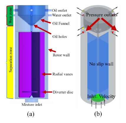
Figure 1 shows cross-sectional views of the newly designed ACC. It primarily comprises two coaxial cylinders where the inner cylinder rotates, and the outer cylinder is stationary. A water–oil mixture was initially injected into the annulus region between the inner rotor and outer stator of the ACC through the tangential ports, resulting in mixing and dispersion in the annulus region owing to shear induced by the rotor. After mixing, the mixture was allowed to flow through the rotor inlet. The rotor was equipped with additional equipment, such as rotating vanes and diverter discs, which improved the separation of the two liquids inside the rotor region. The rotor region could be partitioned into the weir and separation zones. Liquid mixing and emulsification primarily occurred in the separation zone, whereas the separated liquid exited the weir zone. Because the rotor was connected to the motor, it generated a centrifugal force because of the rotating action from the motor, resulting in the upward pumping of the liquids. Consequently, the higher-density liquid propagated toward the wall, whereas the lower-density liquid flowed into the center of the rotor owing to centrifugal force, followed by rapid separation of the mixture into water and oil. Finally, the liquids entered their respective collectors and exited from the outlets. Based on the above mechanism, liquid separation in the ACC rotor was realized for air and water, as shown in Figure 2. The investigated geometry was composed of a separation zone and weir zone. A complete list of the dimensions is presented in Table 1.
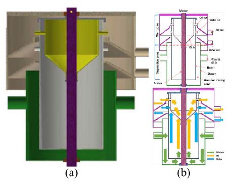
(a) Three-dimensional and (b) two-dimensional cross-sectional views of newly designed annular centrifugal contactor.
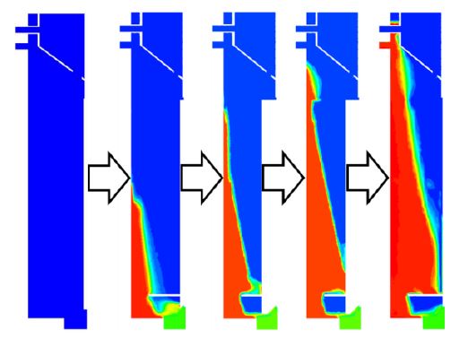
Illustration of air–water separation in annular centrifugal contactor from mixture (green) into air (blue) and water (red).
3. Numerical Methods
3.1 Mesh independence and validation for liquid–liquid separation
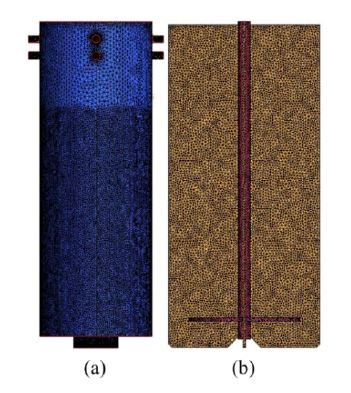
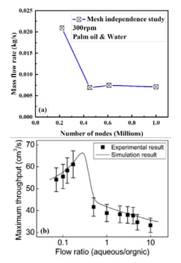
An unstructured mesh for the geometry was generated using Ansys ICEM CFD. Because this geometry involves complex structures, a high mesh refinement near the walls is difficult to maintain. Therefore, mesh increments must be appropriately set to prevent numerical instability and increase accuracy [23]. Hence, a scalable wall function was used to prevent a high mesh refinement near the walls. The scalable wall function (Y + ≥11.26) assumes that the wall surface coincides with a viscous sublayer. Therefore, the fluid cells remain above the viscous sublayer, and inconsistency in prediction owing to near–wall high mesh refinement is avoided. In this study, four different meshes were considered to conduct a mesh-independence test, as shown in Figure 3. It was found that the variations in the number of nodes were not significantly affected by the mass flow rate variations after 430 K nodes, as shown in Figure 4(a). Finally, a mesh size of 620 K was selected to reduce the computational cost and obtain accurate results. All the cases were simulated using the same mesh size. In addition, the mesh density for these simulations was coarse to reduce the high computational cost of calculating the transient simulations using the sliding mesh model. Moreover, extensive experimental and numerical studies on liquid–liquid separation using ACC have been conducted. Therefore, the numerical results of ACC have been validated for liquid–liquid systems with experimental results by the authors [24][25]. The obtained numerical results were consistent with the published experimental results, as shown in Figure 4(b). Hence, this equipment has already been established as an effective two-liquid separator. Because the separation of two liquids using ACC has been reported, the flow behavior and performance of a new ACC with a funnel-type rotor were analyzed numerically in this study to enable further design and separation performance improvement.
3.2 Computational domain and boundary conditions
A funnel-type computational domain was considered to analyze the separation of the two liquids, as shown in Figure 5. The flow behavior is difficult to clarify because mixing and separation co-occur in the rotor. Therefore, rotating vanes were installed, which were required to accelerate the fluid entering the rotor and allow it to spin at a constant rate. A diverter disc was used to increase the flow rate by directing the flow of the mixture entering the rotor radially outward into the separation zone. The properties of the liquids investigated in this study are listed in Table 2. A mixture of oil and water with the same volume fraction ratio (0.5) was used at the inlet. The mixture inlet is defined by the velocity, and the outlets are defined as the pressure outlets. No-slip boundary conditions were adopted for all walls. The surface tension values for the oil and water were 0.025 N/m. The ambient pressure was defined as atmospheric pressure.
3.3 Numerical model and governing equations
A numerical simulation for a three–dimensional ACC rotor was performed assuming unsteady flow using Ansys CFX to analyze liquid separation. The selected geometry consisted of stationary and rotating frames. Therefore, the rotating effect between the rotor and stator was solved using the sliding mesh method. A high-advection resolution scheme and a second-order backward Euler transient scheme were used to discretize the convective term and time, respectively [26]. The maximum Courant number remained lower than five, indicating that the time step was sufficiently short. For the multiphase model, the homogeneous model can be used when the interface between the two phases remains well-defined, and none of the dispersed phases become entrained in the continuous phase. When the dispersed phase becomes entrained in the continuous phase, the inhomogeneous model is a better option than the homogeneous model for achieving improved numerical stability and reduced computational time. It was assumed that the phases were mixed at the macroscopic level, such as the oil droplets in water. Therefore, the Eulerian–Eulerian method was adopted in this study. In this method, the liquid phases share the same volume and penetrate each other in space in the form of dispersed and continuous fluid phases. In addition, this model is suitable for simulating the interface between liquids in the separating region and describing the flow behavior. Complex fluid flows were expected in the rotor owing to the rotating effect of radial vanes. Nonlinear k–ε models, such as the RNG k–ε, SST k–ω, and Reynolds stress models, yield better predictions than the standard k–ε model for complex rotating flow. However, the standard k–ε turbulence model is widely used in industry-problem calculations. The numerical results were compared with the experimental results obtained by the author [9]. The numerical results obtained using the standard k–ε model agreed reasonably well with the experimental results. Furthermore, the obtained results of the standard k–ε model were compared with those of two turbulence models, that is, the Reynolds stress model and SST k–ω models, and showed consistency with these two turbulence models at a moderate rpm. Based on these positive results, the standard k–ε turbulence model was used in our study because it is suitable for simulating complex flow analyses. In this study, oil and water were separated from the mixture with a slight difference in density. The parametric conditions listed in Table 3 were used to analyze the performance of the ACC rotor in separating the two liquids. The governing equations for the “Np” phase are as follows.
The total volume fraction equation is expressed as
| (1) |
the volume conservation equation for incompressibility between phases is expressed as
| (2) |
the continuity equation is expressed as
| (3) |
the momentum equation is expressed as
| (4) |
where Np is the total number of phases, α and β are the phases, rα is the volume fraction, U is the velocity vector, g is the acceleration of gravity, ρ is the density, and P is the pressure. Here, Γαβ describes the mass transfer between the phases and is assumed to be zero because of the absence of evaporation and condensation in this study. In Equation (4), Mαβ represents the total interfacial force exerted on phase α owing to phase β. The total interfacial force exerted on the “Np” phase is attributed to the presence of other phases, including drag, lift, and virtual mass effects. Because the other effects were negligible in the mixing-dominated flow in the ACC, only drag was considered. The drag effects of drops and bubbles must be considered in the two-phase flow of the ACC. Therefore, the Ishii–Zuber drag model was used to evaluate the drag force because this model is applicable to general fluid particles, such as drops and bubbles. Moreover, this model considers spherical and spherical cap limits and dense fluid–particle effects and is, therefore, suitable for modeling flows containing a high fluid volume fraction within the ACC. The mean oil diameter was set to 0.15 mm. The equation for the interfacial force exerted on phase α owing to phase β can be expressed as
| (5) |
where Cαβ is the momentum transfer, defined as
| (6) |
In Equation (6), Aαβ is the interfacial area density associated with the volume fraction (rα) and particle diameter (dp). It can be expressed as
| (7) |
where CD is the drag coefficient of particles, bubbles, or drops. CD can be defined as
| (8) |
where Rep is the particle Reynolds number, which can be expressed as
| (9) |
4. Results and Discussion
4.1 Separation and general flow behavior analysis
The pressure distribution and general flow behavior inside the rotor must be analyzed to reveal the separation phenomenon. In this study, oil and water were separated from the mixture with a slight difference in density. Palm oil and water were selected for this study because of their slight difference in density to evaluate the separation performance of the rotor.
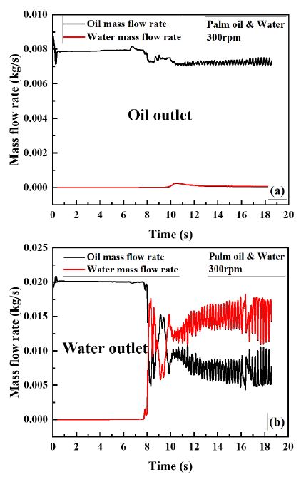
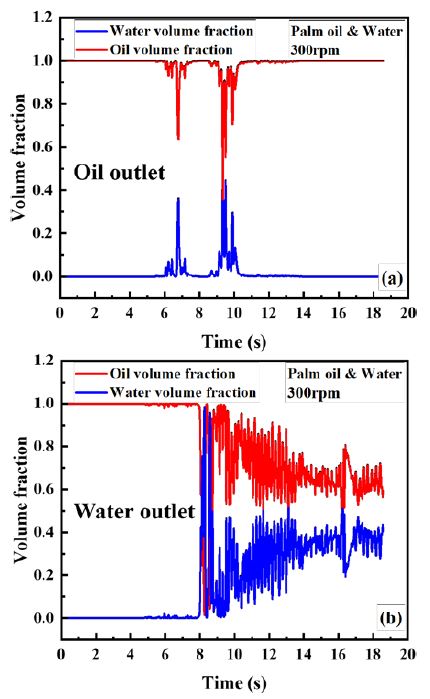
Because the sliding mesh method was adopted in this study, the periodic fluid flow behavior was observed. Hence, the transient fluid flow behavior was monitored at the water and oil outlet at 300 rpm and 0.1 m/s as time progressed, and the results are presented in Figure 6. The oil mass flow rate was high because a rotor filled with oil was assumed during the startup period. As the rotor rotated continuously, the mixture of liquids steadily approached the weir zone, and only random mixing occurred in the separation zone until approximately 6 s, indicating that the injected mixture of liquids required 6 s to reach the weir zone. As the liquids propagated upward owing to centrifugal force, liquid separation commenced after 6 s, and unsteady behavior of the liquids was observed until approximately 12 s. The oil mass flow rate decreased at the oil outlet, whereas the water mass flow rate increased with time at the water outlet simultaneously with mass flow rate fluctuation, as shown in Figures 6(a) and (b). As predicted, the mass flow rate variation stabilized periodically after 12 s. The mass flow rate fluctuation was time periodic owing to the rotor–stator interaction in the ACC.
Figure 7 shows the liquid separation phenomenon at the oil and water outlets. As shown, the rotor was initially filled with oil during the startup period; therefore, the volume fractions of the oil and water were 1 and 0, respectively. As time progressed, the mixture of liquids steadily approached the weir zone from the separation zone where liquid separation occurred. No liquid separation occurred until 4 s; that is, only the mixing was dominant. Subsequently, liquid separation occurred from 4 to 11 s, resulting in the fluctuation of the liquids during this period. The volume fractions of both liquids stabilized after separation, as shown in Figure 7(a). However, a different phenomenon was observed after 8 s (Figure 7(b)). It was discovered that the volume fraction of the oil decreased, and that of water increased at the water outlet as time progressed, indicating the separation of the two liquids.
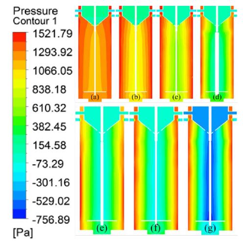
Figure 8 shows a cross-sectional view of the pressure distribution of the ACC rotor. The pressure distribution is critical because it determines the flow conditions of liquids. As expected, high pressure was generated near the wall owing to the centrifugal force. Furthermore, a lower pressure was generated in the oil funnel and the center of the rotor. Figure 8 shows that the pressure difference between the wall and center of the rotating axis increases as the rotating speed increases owing to centrifugal force.
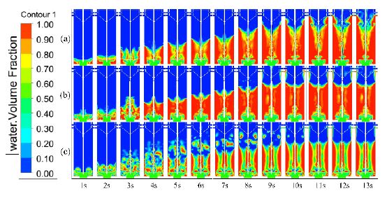
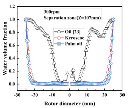
Figures 9 and 10 show that the rotor was initially filled with oil. Phase separation started immediately after the mixed liquid was injected into the rotor because the oil was set as a dispersed phase. As time progressed, the fluid flow rate above the diverter disc increased with decreasing density difference between the liquids. As expected, mixing dominated in random regions of the separation zone. As the rotor induced a pumping effect owing to the radial vanes, higher density liquids such as water propagated toward the rotor wall and pushed the lower density liquid into the center of the rotor. Hence, a significant portion of water occupied the separation zone, and most of the oil was located above the separation zone. Consequently, the flow structure became parabolic when the density difference was high, as shown in Figure 9(a). Finally, instability occurred because of the high interfacial force of the liquids, as shown in Figure 9(c). As the density difference between the liquids decreased, fluid dispersion occurred initially. As time progressed, the flow stabilized, and the water volume fraction in the separation zone decreased as the density difference between the liquids decreased, as shown in Figure 10.
The streamline distributions of superficial velocities of the oil and water for different densities were plotted to visualize the liquid separation and flow behavior (Figure 11).
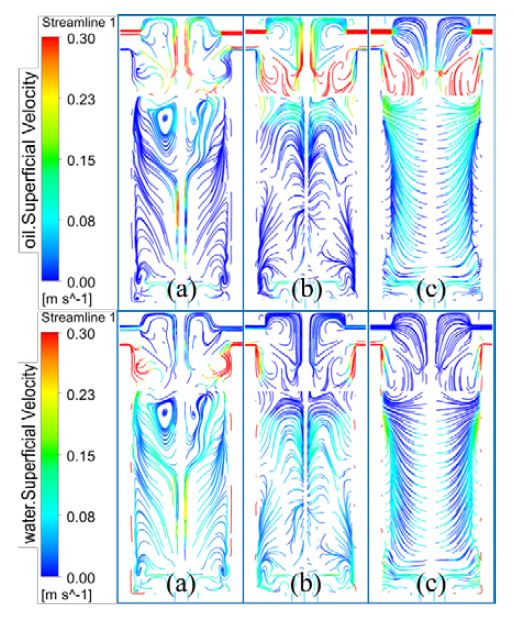
Streamline distributions for superficial velocities of oil and water: (a) oil [25], (b) kerosene, and (c) palm oil
Because the mixture of liquids was initially injected into the rotor, mixing occurred primarily in the separation zones, resulting in turbulent flow behavior. As the liquid propagated upward, a secondary vortex was generated in the separation zones because of the rotational effect generated by the radial vanes, as shown in Figure 11(a). This was expected because of the increased liquid flow and geometrical shape, which resulted in the rapid separation of the two liquids in the weir zone. The oil velocity in the oil funnel decreased with increasing oil density and increased in the separation zone, resulting in decreased separation efficiency at the oil outlet.
4.2 Separation performance analysis
The oil separation efficiency and the quality of oil at the oil outlet in the ACC were calculated as follows to evaluate the separation performance:
| (10) |
| (11) |
where EO and QO are the oil separation efficiency and quality, respectively. mo,in, mo,wo, mo,oo, and mt,oo, are the oil mass flow rate at the inlet, oil mass flow rate at the water outlet, oil mass flow rate at the oil outlet, and the total mass flow rate of the mixture at the oil outlet, respectively.
The ACC separation performance was influenced by the difference between the densities of the liquids. Therefore, three types of liquid density differences were investigated to analyze their effect on the separation performance, as presented in Table 4.
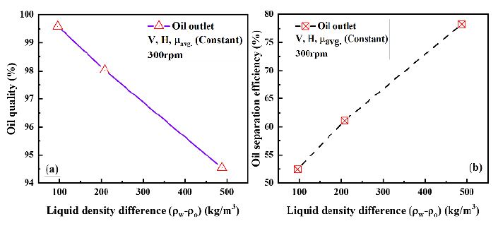
Figure 12 shows the separation performance of the ACC for the three types of oils. As shown in Figure 12(a), the oil quality steadily decreased from 99.25% to 94.54% as the liquid density difference increased, indicating that the amount of pure oil increased even in liquids with a slight density difference at the oil outlet. The oil separation efficiency at the oil outlet increased from 52.32% to 78.28% as the liquid density difference increased, as shown in Figure 12(b).
When the liquid density difference decreased, the oil velocity increased continuously in the separation zone, causing a significant amount of oil to exit through the water outlet. Consequently, the oil separation efficiency decreased with the liquid density difference at the oil outlet, whereas the oil quality increased at the oil outlet.
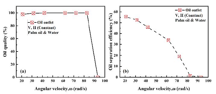
In the previous section, we analyzed the effect of various oils with different density differences. In this section, we focus on separation performance analysis using palm oil and water. The centrifugal force is a critical parameter in liquid separation, as it indicates the rapid separation between two immiscible liquids. The centrifugal force is directly proportional to the angular velocity; therefore, the two liquids might be separated at high angular velocities. The effect of the angular velocity on the separation performance was numerically analyzed for palm oil and water, as shown in Figure 13. The results show that the oil quality slightly increased from 98% to 100% as the angular velocity increased to 790 rpm and then started to decrease significantly with the angular velocity at the oil outlet, as shown in Figure 13(a). This result is attributed to increased centrifugal force with angular velocity, which can increase the oil quality at the oil outlet. Figure 13(b) shows that the oil separation efficiency decreases as the angular velocity at the oil outlet increases. The oil quality and separation efficiency became zero when the angular velocity was approximately 890 rpm, indicating that this system does not function as intended above 890 rpm. When the rotor rotated at high speed, the lower-density liquid did not occupy the center region of the rotor because of the high centrifugal force, causing the oil to exit with water at the water outlet. Hence, no oil was detected at the oil outlet, which led to the poor performance of the ACC.
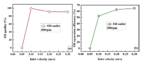
Figure 14 shows the effect of the inlet velocity on the oil quality and separation efficiency at 300 rpm. The oil quality and separation efficiency at low velocities were zero at the oil outlet, however, the oil quality at the oil outlet reached approxiately 99% at 0.1 m/s and then started decreasing steadily as the inlet velocity increased, as shown in Figure 14(a). In contrast, the oil separation efficiency increased at the oil outlet as the inlet velocity increased, as shown in Figure 14(b). It means that oil quality and separation efficiency are less affected by inlet velocity at relatively high inlet velocity region. Because the flow rate in the rotor increased as the inlet velocity increased, a significant amount of oil propagated through the oil outlet.
5. Conclusion
A new type of ACC was numerically investigated to analyze the liquid separation performance using Ansys CFX. A numerical simulation of a liquid–liquid two-phase flow was performed in the ACC using an Euler–Euler multiphase model. A homogeneous k–ɛ turbulence model with a scalable wall function was used to clarify the turbulent multiphase flow characteristics. The rotational effect between the rotor and stator was evaluated using the sliding-mesh method. A detailed parametric study with variations in the liquid density difference, angular velocity, and inlet velocity of the mixture was performed to analyze the flow fields and separation performance of the rotor. Based on our simulation analysis, the following conclusions are drawn:
- 1. The oil separation efficiency increased from 52.32% to 78.28% as the liquid density difference increased, whereas the oil quality steadily decreased from 99.25% to 94.54% as the liquid density difference increased, indicating that almost pure oil was obtained from the mixture.
- 2. The oil quality in the palm oil–water mixture increased slightly from 98% to 100% when the angular velocity increased from 200 to 790 rpm but decreased significantly as the angular velocity exceeded 790 rpm. The oil separation efficiency decreased continuously as the angular velocity increased at the oil outlet. This shows that the separation of two liquids with a low difference in density does not require a high rotating speed operation.
The oil quality sharply increased from 0% to 99.37% at 300 rpm when the inlet velocity increased from 0.05 to 0.1 m/s and then decreased steadily as the inlet velocity at the oil outlet increased. The oil separation efficiency increased from 0% to 65% as the inlet velocity increased from 0.05 to 0.3 m/s. It can be concluded that the ideal inlet velocity for this ACC is 0.1 m/s or higher.
Acknowledgments
The paper is a revised version of a paper entitled “Numerical Analysis of an Annular Centrifugal Contactor for Liquid-Liquid Separation” presented at ISMT 2021, Busan, Korea, 21-23 October 2021. And this work was supported by a Research Grant of Pukyong National University (2021).
Author Contributions
Conceptualization, P. Chakma and Y. W. Lee; Methodology, P. Chakma and J. Jeon; Software, P. Chakma; Formal Analysis, P. Chakma and Z. Hongwu; Investigation, P. Chakma; Resources, Y. W. Lee; Data Curation, P. Chakma and J. Jeon; Writing-Original Draft Preparation, P. Chakma; Writing-Review & Editing, Z. Hongwu, J. Jeon and Y. W. Lee; Visualization, P. Chakma; Supervision, Y. W. Lee; Project Administration, Y. W. Lee; Funding Acquisition, Y. W. Lee.
References
-
M. Hao, Z. Bai, H. Wang, and W. Liu, “Removal of oil from electric desalting wastewater using centrifugal contactors,” Journal of Petroleum Science and Engineering, vol. 111, pp. 37-41, 2013.
[https://doi.org/10.1016/j.petrol.2013.10.017]

-
Q. Xia, and P. MA, “Measurement and correlation for solubility of dimethyl-2, 6-naphthalene dicarboxylate in organic solvents,” Chinese Journal of Chemical Engineering, vol. 15, no. 2, pp. 215-220, 2007.
[https://doi.org/10.1016/S1004-9541(07)60061-5]

-
W. Duan, C. Song, Q. Wu, X. Zhou, and J. Zhou, “Development and performance of a new annular centrifugal contactor for semi‐industrial scale,” Separation Science and Technology, vol. 40, no. 9, pp. 1871-1883, 2005.
[https://doi.org/10.1081/SS-200064531]

-
M. Ilmi, A. Kloekhorst, J. G. M. Winkelman, G. J. W. Euverink, C. Hidayat, and H. J. Heeres, “Process intensification of catalytic liquid-liquid solid processes: Continuous biodiesel production using an immobilized lipase in a centrifugal contactor separator,” Chemical Engineering Journal, vol. 321, pp. 76-85, 2017.
[https://doi.org/10.1016/j.cej.2017.03.070]

-
H. Jiang, Y. Tang, and Q. X. Guo, “Separation and recycle of phenol from wastewater by liquid–liquid extraction,” Separation Science and Technology, vol. 38, no. 11, pp. 2579-2596, 2003.
[https://doi.org/10.1081/SS-120022289]

-
X. Jing, P. Ning, H. Cao, J. Wang, and Z. Sun, “A review of application of annular centrifugal contactors in aspects of mass transfer and operational security,” Hydrometallurgy, vol. 177, pp. 41-48, 2018.
[https://doi.org/10.1016/j.hydromet.2018.02.005]

- J. D. Law and T. A. Todd, “Liquid-liquid extraction equipment,” Idaho National Laboratory (INL), 2008, USA.
-
Q. Luo, S. Li, and S. Jing, “The study of fluid dynamics in countercurrent multi-stage micro-extraction system,” Energy Procedia, vol. 39, pp. 275-282, 2013.
[https://doi.org/10.1016/j.egypro.2013.07.214]

-
H. Ghaya, R. Guizani, H. Mhiri, and P. Bournot, “CFD study of the effect of geometrical shape of separation blades on the rotor performance of an Annular Centrifugal Extractor (ACE),” Journal of Applied Fluid Mechanics, vol. 12, no. 4, pp. 1189-1202, 2019.
[https://doi.org/10.29252/jafm.12.04.29579]

-
G. J. Bernstein, D. E. Grosvenor, J. F. Lenc, and N. M. Levitz, “A high-capacity annular centrifugal contactor,” Nuclear Technology, vol. 20, no. 3, pp. 200-202, 1973.
[https://doi.org/10.13182/NT73-A31358]

-
J. Zhou, W. Duan, X. Zhou, and C. Zheng, “Application of annular centrifugal contactors in the extraction flowsheet for producing high purity yttrium,” Hydrometallurgy, vol. 85, no. 2-4, pp. 154-162, 2007.
[https://doi.org/10.1016/j.hydromet.2006.08.010]

-
W. Duan, T. Sun, and J. Wang, “Separation of Nd3+ and Fe3+ by non-equilibrium solvent extraction using an annular centrifugal contactor,” Separation and Purification Technology, vol. 146, pp. 108-113, 2015.
[https://doi.org/10.1016/j.seppur.2015.03.044]

-
S. Kumar, B. Kumar, P. K. Sinha, M. Sampath, D. Sivakumar, and U. K. Mudali, “Extraction of uranium from simulated highly active feed in a micromixer-settler with 30% TBP and 36% TiAP solvents,” Journal of Radioanalytical and Nuclear Chemistry, vol. 311, no. 3, pp. 2111-2116, 2017.
[https://doi.org/10.1007/s10967-016-5134-5]

-
X. Jing, J. Wang, H. Cao, P. Ning, and Z. Sun, “Rapid selective extraction of V (V) from leaching solution using annular centrifugal contactors and stripping for NH4VO3,” Separation and Purification Technology, vol. 187, pp. 407-414, 2017.
[https://doi.org/10.1016/j.seppur.2017.06.078]

-
K. Tang, Y. Wang, P. Zhang, Y. Huang, and G. Dai, “Process optimization of continuous liquid–liquid extraction in centrifugal contactor separators for separation of oxybutynin enantiomers,” Separation and Purification Technology, vol. 150, pp. 170-178, 2015.
[https://doi.org/10.1016/j.seppur.2015.06.027]

-
X. Jing, P. Ning, H. Cao, Z. Sun, and J. Wang, “Separation of V (V) and Cr (VI) in leaching solution using annular centrifugal contactors,” Chemical Engineering Journal, vol. 315, pp. 373-381, 2017.
[https://doi.org/10.1016/j.cej.2017.01.014]

-
D. H. Meikrantz, L. L. Macaluso, W. D. Flim, C. J. Heald, G. Mendoza, and S. B. Meikrantz, “A new annular centrifugal contactor for pharmaceutical processes,” Chemical Engineering Communications, vol. 189, no. 12, pp. 1629-1639, 2002.
[https://doi.org/10.1080/00986440214582]

-
Y. Xu, J. Wang, S. Zhao, and Z. Bai, “PIV experimental study on the flow field in the rotor zone of an annular centrifugal contactor,” Chemical Engineering Research and Design, vol. 94, pp. 691-701, 2015.
[https://doi.org/10.1016/j.cherd.2014.10.009]

-
A. Eggert, T. Kogl, W. Arlt, and A. Jupke, “Computer tomographic detection of the liquid–liquid mixing and separation within the Annular Centrifugal Contactor/Extractor,” Chemical Engineering Research and Design, vol. 142, pp. 143-153, 2019.
[https://doi.org/10.1016/j.cherd.2018.11.034]

-
A. Eggert, S. Sibirtsev, D. Menne, and A. Jupke, “Liquid–liquid centrifugal separation—New equipment for optical (photographic) evaluation at laboratory scale,” Chemical Engineering Research and Design, vol. 127, pp. 170-179, 2017.
[https://doi.org/10.1016/j.cherd.2017.09.005]

-
K. E. Wardle, T. R. Allen, and R. Swaney, “CFD simulation of the separation zone of an annular centrifugal contactor,” Separation Science and Technology, vol. 44, no. 3, pp. 517-542, 2009.
[https://doi.org/10.1080/01496390802634398]

- N. T. Padial‐Collins, D. Z. Zhang, Q. Zou, X. Ma, and W. B. VanderHeyden, “Centrifugal Contactors: Separation of an aqueous and an organic stream in the rotor zone (LA‐UR‐05‐7800),” Separation Science and Technology, vol. 41, no. 6, pp. 1001-1023, 2006.
-
H. Kim, P. Nanjundan, J. Jeon, and Y. W. Lee, “Numerical estimation on applying air-trapping mechanism to suppress sloshing loads in a prismatic tank,” Journal of Mechanical Science and Technology, vol. 34, no. 7, pp. 2895-2902, 2020.
[https://doi.org/10.1007/s12206-020-0621-6]

-
S. Li, W. Duan, J. Chen, and J. Wang, “CFD simulation of gas–liquid–liquid three-phase flow in an annular centrifugal contactor,” Industrial & Engineering Chemistry Research, vol. 51, no. 34, pp. 11245-11253, 2012.
[https://doi.org/10.1021/ie300821t]

- C. Rosales, M. Barron, I. Hilerio, and D. Medina, “Computer simulation of water-oil separation in cylindrical and square hydrocyclones,” Proceedings of the 2011 international conference on modeling, simulation & visualization methods, pp. 121-124, 2011.
-
H. Kim, M. K. Dey, N. Oshima, and Y. W. Lee, “Numerical study on sloshing charateristics with Reynolds number variation in a rectangular tank,” Computation, vol. 6, no. 4, p. 53, 2018.
[https://doi.org/10.3390/computation6040053]


