A study on the effects of self-piercing riveting methods on the joint
Copyright ⓒ The Korean Society of Marine Engineering
This is an Open Access article distributed under the terms of the Creative Commons Attribution Non-Commercial License (http://creativecommons.org/licenses/by-nc/3.0), which permits unrestricted non-commercial use, distribution, and reproduction in any medium, provided the original work is properly cited.
Abstract
As the regulations on exhaust gas strengthened, the research and development of devices to reduce air pollutants emitted from vehicles have continued. Lightweight design that influences the fuel efficiency of vehicles has become an essential consideration due to the use of exhaust gas reduction systems. The early lightweight design started as a concept of replacing steel materials with aluminum or ultrahigh tensile steel. However, bi-metals with high strength and light weight are now being designed and developed instead of single materials. For bonding of bi-metal sheets, the self-piercing riveting method is being generally applied to double sheets with an upper high-tensile steel plate and a lower aluminum alloy plate. However, there is insufficient research to solve the problem of the costs of power consumption and consumable parts and low bonding strength of the joint due to the potential corrosion of parts that occur in the rivet joint. This study proposed a new self-piercing riveting method after punching (SPRP) method that can prevent the reduction of bonding force of the rivet joint and minimize the stress and forming load required for bonding. Furthermore, the possibility of rivet bonding with corrosion resistance and bonding force was proved through experiment and analysis.
Keywords:
Bi-metal sheets, Corrosion resistance, Finite element method simulation, Shear strength, Self-piercing riveting method after punching (SPRP), Weight lightening design1. Introduction
The reduction of exhaust gas and the achievement of fuel efficiency through the realization of lightweight parts are still the key elements of development in the automotive industry. In particular, the research about lightweight car body using bi-metals is essential to satisfy environmental regulations. The achievement of excellent mechanical properties and the verification of bonding between materials in the manufacture of bi-metal parts are becoming important with the adoption of aluminum as a material for lightweight. The resistance spot welding (RSW) may not be suitable for automotive parts using bi-metals according to the difference in the material properties in terms of thermal deformation, and the bonding method using rivets is generally applied [1]. The self-piercing riveting (SPR) method known as a representative mechanical bonding method uses an upper sheet that is deformed by punch and rivet and lower sheet deformed by a bottom die and rivet. The SPR process is conducted in six steps: positioning, holding, piercing, stamping, forming, and setting [2]. In the process after holding among these steps, the forming load and friction heat that occur when penetration of the upper and lower sheets occurs due to the pressing force of the punch are involved in the shape of the plastically deformed rivet and affect the bonding force of bi-metal parts. As the SPR process is being used more frequently, the fracture mechanism at the joint of bi-metal needs to be analyzed in depth. Most preliminary studies mainly discuss the comparison of mechanical properties of the joint according to the application of SPR and RSW [3]. Kenichiro Mori et al. analyzed the reduction of the yield strength of materials in the RSW process in contrast to the increase in the yield strength of bonding materials due to the work hardening effect when the SPR process was applied and proved that the SPR method has the better fatigue properties than the RSW method [4]. Marc Reinstettel analyzed the decrease in the fatigue strength of material and the increase in the slope of the S-N curve when the RSW method was applied and verified that the durability was relatively low when the SPR method was applied [5]. The SPR process should be designed by considering changes in physical properties such as the yield point of the part material of the joint and rivet and the strain hardening phenomenon during forming. However, the rivet should be designed with a material having high strength in order to penetrate a high-strength bi-metal through piercing. Because rivets are used as consumables in SPR, the individual manufacture of rivets suitable for various types of bonding materials lower economic efficiency and production efficiency. This study proposes SPRP as a new method considering the forming load and lightweight according to the mechanical properties of bi-metal. Furthermore, an attempt was made to achieve the versatility of rivet made of the same material by analyzing the effects of the shape change of rivet manufactured by punching method using Al2024 on the joint.
2. Reliability Evaluation on the SPRP
2.1 Methods
A design that can minimize rollover and burr may occur in the top and bottom of the shear surface during shearing with a punch die on a GPa-grade high-strength plate is required before riveting [6]. Hong-Seok Choi et al. demonstrated through experiments that when the size of the inclination angle of a plate is -20° or less, the properties of the shear fracture surface including the reduction of burr for additional processing are improved [7]. Sutasn Thipprakmas et al. analyzed the effect of the taper shape of punch on the rollover and burr length and proved that the taper shape can be selected by the design variables of punch that can control the shear surface shape [8]. Nobuhiko Takeuchi et al. researched on the effect of the clearance size between the tool and material on the rollover and burnish length on the shear surface of mild steel and demonstrated that the effect of clearance on the shear surface may vary by the selected material [9]. The present study selected sheet angle, taper shape, clearance, and round edge as the design variables of the punching process, and analyzed the shape of the shear fracture surface when a hole was formed on bi-metal sheets at the punch velocity of 5 mm/s. FEM simulation was performed about the punching process in advance and the shapes of the shear fracture surface were compared by conducting punching experiments to derive the conditions for obtaining the most suitable shape of the shear fracture surface shown in Figure 1 when the riveting process was applied.
The forming analysis and actual experiments were performed to examine the differences in the internal shear fracture surface of the hole according to the shape of the punch die and processing conditions before performing riveting on a bi-metal sheet composed of a 1.2 mm-thick SK5 upper sheet and a 2 mm-thick Al6061-T6 lower sheet. A tool made of H13 material with excellent wear resistance to hardness at high temperature was used. Regarding the outer sheet material for strength, SK5, which is mainly used in the automotive industry, was selected. Although the martensite phase is formed and weldability decreases as the carbon content in the steel increases, but it is suitable for the SPRP process because of high hardness and strength [10]. For the material of the inner sheet, Al6061-T6, a representative car body material that is advantageous for strength and lightweight, was used. For the rivet, Al2024-T3, an aluminum alloy with a high tensile strength, was selected [11].
2.2 Forming simulation of SPRP
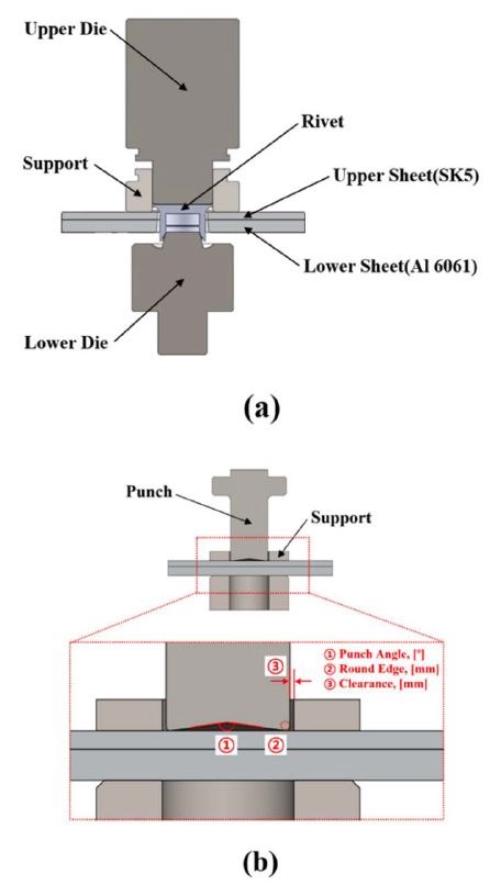
The finite element modeling for the riveting process and punching process was performed as shown in Figure 2(a, b), respectively. And forming simulation was performed in order to examine the dimensional trend of shear surface according to design parameters of SPRP process and to identify the load and deformed shape that occur in the riveting work required for bi-metal bonding. The material properties used in the analysis are listed in Table 1. The shape variables of the punch in the punching process were selected as shown in Table 2. The existing self-piercing riveting process has to create gaps in sheets without holes by riveting, so the strength design of the rivet was limited by the mechanical properties of the sheets, but there is no limit to the selection of materials for the rivet on the SPRP Process suggested in this study. The design variables of the riveting process were analyzed regarding the combinability with bi-metal sheet materials when the punch entry angle was applied from 0° to 10° at 2.5° intervals. Angle in Table 2 refers to the angle formed by the center and edge when a taper was given toward the inside of the bottom shape of the punch. Round edge refers to the rounding value that rounds the bottom edge of the punch to avoid contact between the tool and the burr on the shear surface that was generated on the material when the tool was removed after punching. The DEFORM V12 and ANSYS v.20 R2 Static Structural Module were used regarding the finite element analysis programs in order to secure data on each process.
Finite element models were designed with the number of nodes of 4924, 4137, and 1104 and the number of elements of 4712, 3971, and 1000 in the order of upper sheet, lower sheet, and rivet, which were specified as strong plastic materials. The pressurization speed of the punch was 5 mm/s and the shear friction coefficient of 0.12 was assigned, which is mainly used in cold forming related to the friction condition between the tool and base metal. The diameter of the hole generated by punching process was 8 mm. The force by which the support and lower die fixed the bi-metal sheets when riveting was set to 10kN.
2.3 Experimental evaluation on the SPRP
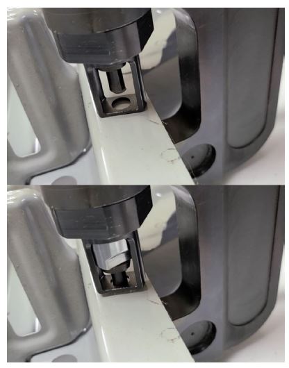
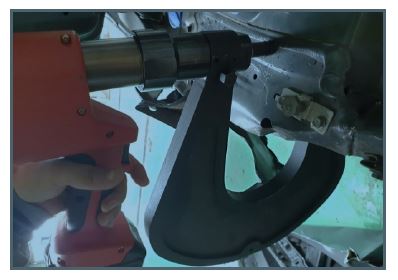
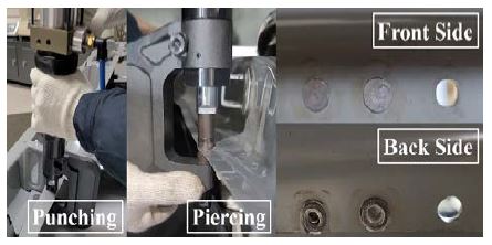
In this experiment, the SPRP process was actually conducted to verify the reliability of the result data of the forming simulation as shown in Figures 3 and 4. The processing characteristics of the shear surface according to the shape variable and process conditions of the punch were identified and compared with the analysis result. Then the optimal process conditions were selected by considering the stress distribution and load values during forming.
3. Experimental and Calculated Results
3.1 Results of punching process
The shape of the shear surface inside the hole of a bi-metal sheet processed by punching according to eight cases of forming condition settings according to the shape variable design is shown in Figure 5 and 6.
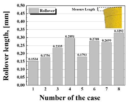
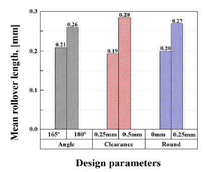
The overall rollover length showed a tendency to be minimized when the angle was 165°, the clearance was 0.25 mm, and the round edge was 0 mm called Case1 shown in Figure 5 and when compared with Case 5, the rollover length in Case 1 decreased more by 0.0259mm than Case 5 if only the die angle is considered as a variable. In every case of design in this study, the rollover length increased in proportion to the clearance and round edge size. Regarding the shape of the punch, fracture occurred when the penetration depth of the punch with no rounding into a material was 1.1 mm on average. In the 0.25mm rounding condition, the shear fracture surface was mainly formed at the outer diameter of the punch at the average punch penetration depth of 1.4 mm. The case of processing a hole with a tool without round condition showed a result of decreasing the rollover length on the shear surface. Therefore, in terms of shape, the punch shapes of Cases 1 and 5 for which the clearance and round edge values were designed to be the lowest were determined to be suitable conditions for minimizing rollover. However, an analysis of the stress distribution during punching is indispensable because the objective of this study is to minimize power consumption for processing by controlling the forming load in the SPRP process and create economic efficiency by preventing tool wear due to local stress. In this regard, the principal stress value according to the forming times at the center and edge of the punch when the punch comes in contact with the bi-metal is shown in Figure 7. With respect to the tool, a higher tensile principal stress acted on the edge of the tool in the shapes of Cases 1 to 4 than Cases 5 to 8. This was caused by the difference in the punch shape resulting from the different angle conditions. When the sheet is pressurized, a tensile stress mainly acts at the center of the punch due to the rotational moment. The tensile stress at the center was measured higher in Cases 1 to 4 due to the geometric characteristics resulting from the differences in the designed punch angle. Furthermore, a higher tensile principal stress occurred when the round edge was 0 mm in the same angle condition, and the compressive principal stress increased in proportion to the value of the round edge. The maximum principal stress value calculated in every case using finite element method is lower than the yield strength of H13, the tool material, it would not significantly affect the use and lifespan of the tool except for wear caused by repeated loading of the tool. Depending on the angle condition, the tensile principal stress at the center of the punch was higher by up to 370 MPa when the angle was 165° than when it was 180°. The compressive principal stress did not show any specific trend according to the angle. The clearance value set in relation to the positioning of the bi-metal used in this study did not show a significant principal stress increased in proportion to the value of the round edge. The maximum principal stress value in every case is lower than the yield strength of H13, the tool material, it would not significantly affect the use and lifespan of the tool except for wear caused by repeated loading of the tool. Depending on the angle condition, the tensile principal stress at the center of the punch was higher by up to 370 MPa when the angle was 165° than when it was 180°. The compressive principal stress did not show any specific trend according to the angle. The clearance value set in relation to the positioning of the bi-metal used in this study did not show a significant effect on the compressive principal stress load while the tensile principal stress was inversely proportional to the clearance. The effective stress generated at the edge of the tool which was 0.25mm rounded during the punching process was calculated lower by approximately 300 MPa than that of the tool that was not rounded and the load was measured lower by approximately 0.2 ton. The maximum compressive principal stress at the edge of the punch showed the largest difference between Cases 2 and 3. Case 4, of which the clearance was larger by 0.25 mm than Case 2, showed a little lower compressive principal stress. The maximum forming load in the punching process was measured as 2.3–2.6 tons and it was found that the hole process was completed faster when there was no rounding condition. Consequently, the shape of Case 5, which showed a lower maximum tensile principal stress in the tool than Case 1, was selected as the optimal punching process condition for hole processing and the riveting process was performed based on Case 5 and the results were analyzed.
3.2 Results of self-piercing riveting process
The hole processing was performed by applying the conditions of Case 5 with an angle of 180°, a clearance of 0.25mm, and a round edge of 0mm selected considering the punching process according to the shape variable design of the tool. This is to make flexible strength design criteria of the rivet due to the differences in the mechanical properties between sheets and rivet during piercing using rivet for bi-metal sheets in the conventional self-piercing riveting process. The process design should be performed in such a way that the hole shape would not be deformed in order to remove the rivet of the joint for the replacement and repair of the car body in the event of an actual vehicle accident and to comply with the method proposed in this study.
Furthermore, even if a hole of specific diameter is processed in a bi-metal sheet, the entry angle of the tool cannot be always the same according to the processing technique of the field worker. Therefore, the deformed shape and bonding force according to the yield strength of the rivet need to be analyzed when riveting process is performed after processing the hole according to the entry angle [12]. Therefore, the process parameter of the entry angle was set to 0°, 3°, 5°, 7°, and 9°. The rivet deformed shapes when the bi-metal sheets were combined by applying the riveting process to the hole formed by each forming condition are shown in Figure 8. The larger the entry angle size, the larger effective strain occurred on the rivet. This is thought to be because the size of the internal space that needs to be filled for combination varies as the rivet is plastically deformed according to the piercing angle of the processed hole. That is, it means that the effective strain rate is determined according to the size of the inner space where the deformation of the rivet can occur. Furthermore, as the entry angle increased, the lower curved part of the head part of the rivet where a deformation occurs during riveting came in contact with the edge part of the upper sheet, which caused a difference in the initial forming point of the rivet. As a result, the material volume for rivet filling in the lower die increased, resulting in a higher value of the effective strain. The size of the cavity between the side wall of the rivet and the inside of the hole of the sheets according to the entry angle was the largest when the entry angle was 3° and the smallest when it was 0°. Such a result of forming can prevent the decline of the bonding strength due to the unfilled part through a modification of the new rivet’s shape to be used in the proposed SPRP process. This means that the design should be changed according to the mechanical properties of the rivet material and bi-metal sheet [13]. Consequently, by referring to the results of experiments conducted in this study, bonding was performed by applying the SPRIP process using rivets made of Al2024 on sheets composed of SK5 for the outer sheet and Al6061 for the inner sheet. The experiment results are shown in Figure 9. The reliability for the application of the SPRP process to bi-metals sheets was verified.
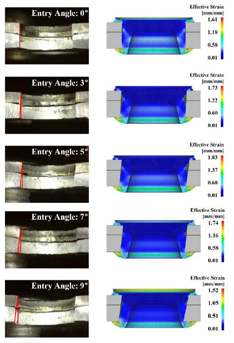
Effective strain of rivets according to entry angle on self-piercing riveting method after punching process
4. Discussion
In relation to the bonding strength of riveting, it is thought that additional research is needed to understand the difference in bonding strength and the applicable range through the SPR Process and SPRP Process, which were mainly used in the past. In this study, considering the dimensions of the designed rivet, the hole with a diameter of 1mm larger than that was processed with a punch, but riveting experiments are required for rivets of different dimensions of the same materials. Considering that the cavity of the rivet tends to increase as the strength of the upper plate base material increases, it is necessary to select an appropriate material for the lower plate and rivet that can reduce the cavity [14]. There are various types of rivets depending on the head shape, and the optimal punch design criteria for the SPRP process will also vary depending on the structural difference of the rivet in contact with the punch [15]. If it is judged that the design of the tool to prevent the hole from being poorly processed by punching is unproductive, the design range for the punch can be reduced by using a reamer on the inner surface of the hole to improve the overlapping precision. And if it is necessary to improve the joint strength, it is also possible to consider whether to drill through a hand reamer to use a rivet of a different size. It is necessary to review the safety design in consideration of the decrease in strength occurring in the joint due to the punching process, and this can be supplemented by riveting technology. Even if the rivet joint is treated, it is not permanent and has the advantage of being able to remove the rivet and generating less noise. When processing rivet joints, the efficiency should be calculated after considering the tensile and shear strengths of bi-metal sheets and rivets.
5. Conclusion
In this study, the optimal tool shape for the punching process was selected by analyzing the shear surface inside the hole and formability during the hole processing of the bi-metal sheet for the designed punch shape. In addition, the factors that influence the bonding strength of the rivetted bi-metal sheets according to the size of the entry angle were analyzed. Furthermore, forming load and the stress on the tool, which are affected by mechanical properties, were minimized by applying self-piercing riveting process after punching, a new method proposed in this study, and the possibility of riveting with a large bonding strength was proved. Regarding the riveting task performed after the pre-reviewed punching process, the rollover length at the edge of the upper sheet that comes in direct contact with the bottom of the rivet’s head was investigated. It was found that the occurrence of rollover was influenced by the shape, clearance and round edge length according to the angle design of the tool. The rollover length increased in proportion to the length of the given clearance and round edge length. A larger tensile principal stress acted on the edge of the tool when the angle condition assigned to the tool was 165° than when it was 180°. Furthermore, a larger tensile stress acted at the center of the tool due to the rotational moment when the sheet was pressurized. The clearance value did not have a significant effect on the compressive principal stress related to the forming load. However, the measured maximum tensile principal stress was inversely proportional to the clearance. The effective stress at the edge of the tool, which was 0.25mm rounded during the punching process, was lower than that of the tool with no rounding, and the forming load was also measured lower by approximately 0.2 ton. The maximum forming load in the punching process was measured at 2.6 ton. It was confirmed that the processing speed increased when the rounding condition was not applied. The possibility of applying the riveting process with a large bonding strength using a rivet on the processed hole according to the entry angle of the punch was verified through experiments and analysis. In conclusion, the appropriateness of the SPRP process for bonding of bi-metal sheets was verified.
Author Contributions
Conceptualization, H. G. Park; Formal Analysis, H. G. Park; Investigation, H. G. Park; Resources, H. G. Park; Data Curation, H. G. Park; Writing—Original Draft Preparation, H. G. Park; Writing—Review & Editing, H. G. Park; Visualization, H. G. Park; Supervision, H. G. Park; Project Administration, H. G. Park; Funding Acquisition, H. G. Park.
References
-
M. Lou, Y. Li, Y. Li, and G. Chen, “Behavior and quality evaluation of electroplastic self-piercing riveting of aluminum alloy and advanced high strength steel,” Journal of Manufacturing Science and Engineering, vol. 135, no. 1, p. 011005, 2013.
[https://doi.org/10.1115/1.4023256]

-
A. Gay, F. Lefebvre, S. Bergamo, F. Valiorgue, P. Chalandon, P. Michel, and P. Betand, “Fatigue performance of a self-piercing rivet joint between aluminum and glass fiber reinforced thermoplastic composite,” International Journal of Fatigue, vol. 83, part 2, pp. 127-134, 2016.
[https://doi.org/10.1016/j.ijfatigue.2015.10.004]

-
H. Q. Ang, “An overview of self-piercing riveting process with focus on joint failures, corrosion issues and optimization techniques,” Chinese Journal of Mechanical Engineering, vol. 34, no. 2, pp. 1-25, 2021.
[https://doi.org/10.1186/s10033-020-00526-3]

-
K. Mori, Y. Abe, and T. Kato, “Mechanism of superiority of fatigue strength for aluminum alloy sheets joined by mechanical clinching and self-piercing rivet,” vol. 212, no. 9, pp. 1900-1905, 2012.
[https://doi.org/10.1016/j.jmatprotec.2012.04.017]

- M. Reinstettel, Laboruntersuchung zur Prozessstabilität beim NietClinchen (Investigation of Process Stability of Rivet-Clinching),’’ Ph. D. Dissertation, Department of Mechanical Engineering, Chemnitz University of Technology, Germany, 2007 (in German).
-
H. S. Choi, B. M. Kim, and D. C. Ko, “Effect of clearance and inclined angle on sheared edge and tool failure in trimming of DP980 sheet,” Journal of Mechanical Science and Technology, vol. 28, no. 6, pp. 2319-2328, 2014.
[https://doi.org/10.1007/s12206-014-0522-7]

-
S. Thipprakmas, S. Rojananan, and P. Paramaputi, “An investigation of step taper-shaped punch in piercing process using finite element method,” Journal of Materials Processing Technology, vol. 197, no. 1-3, pp. 132-139, 2008.
[https://doi.org/10.1016/j.jmatprotec.2007.06.022]

-
N. Hatanaka, K. Yamaguchi, and N. Takakura, “Finite element simulation of the shearing mechanism in the blanking of sheet metal,” Journal of Materials Processing Technology, vol. 139, no. 1-3, pp. 64-70, 2003.
[https://doi.org/10.1016/S0924-0136(03)00183-3]

-
Y. D. Chung, H. Fujii, R. Ueji, and K. Nogi, “Friction Stir Welding of Hypereutectoid Steel (SK5) blow eutectoid temperature,” Science and Technology of Welding and Joining, vol. 14, no. 3, pp 233-238, 2009.
[https://doi.org/10.1179/136217109X415901]

-
M. G. Kil, J. S. Yoon, J. W. Park, and B. S. Kang, “Comparative study of applicability of aluminum, magnesium and copper alloy sheets using flexibly-reconfigurable roll forming,” Transactions of Materials Processing, vol. 26, no. 3, pp. 168-173, 2017 (in Korean).
[https://doi.org/10.5228/KSTP.2017.26.3.168]

-
Y. Zhou and Q. Fei, “Evaluation of opening-hole shapes for rivet connection of a composite plate,” Journal of Mechanical Engineering Science,” vol. 231, no. 20, pp. 3810-3817, 2017.
[https://doi.org/10.1177/0954406216652169]

-
N. H. Hoang, R. Porcaro, M. Langseth, and A. G. Hanssen, “Self-piercing riveting connections using aluminium rivets,” International Journal of Solids and Structures, vol. 47, no. 3-4, pp. 427-439, 2010.
[https://doi.org/10.1016/j.ijsolstr.2009.10.009]

-
T. E. Jeong, M. G. Kim, S. Rhee, and D. H. Kam, “Joint quality study of self-piercing riveted aluminum and steel joints depending on the thickness and strength of base metal” Journal of Welding and Joining, vol. 37, no. 3, pp. 212-219, 2019.
[https://doi.org/10.5781/JWJ.2019.37.3.3]

-
B. Uhe, C. M. Kuball, M. Merklein, and G. Meschut, “Improvement of a rivet geometry for the self-piercing riveting of high strength steel and multi material joints,” Production Engineering, vol. 14, pp. 417-423, 2020.
[https://doi.org/10.1007/s11740-020-00973-w]

-
K. Martinsen, S. J. Hu, and B. E. Carlson, “Joining of dissimilar materials,” CIRP Annals, vol. 64, no. 2, pp. 679-699, 2015.
[https://doi.org/10.1016/j.cirp.2015.05.006]


