Diesel engine generator configuration and operation strategy for the integrated fully electric propulsion destroyer based on the actual operation profile
Copyright ⓒ The Korean Society of Marine Engineering
This is an Open Access article distributed under the terms of the Creative Commons Attribution Non-Commercial License (http://creativecommons.org/licenses/by-nc/3.0), which permits unrestricted non-commercial use, distribution, and reproduction in any medium, provided the original work is properly cited.
Graphical Abstract
Abstract
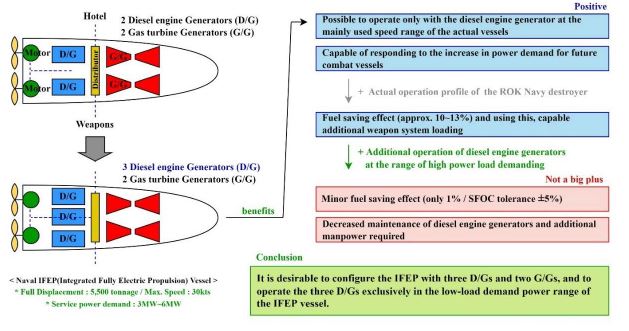
Looking at the case of the UK navy, which adopted integrated fully electric propulsion (IFEP) as a vessel's propulsion system prior to the Republic of Korea (ROK) navy, various problems were derived from the aspects of the IFEP generator selection and operation. Moreover, recently, the UK navy has decided to increase the number of diesel engine generators from two to three. Based on this, the ROK navy is also considering the number of diesel engine generators for the next destroyer. In this research, when the propulsion system of destroyers currently operated by the ROK navy was configured based on IFEP, the changes in the fuel consumption owing to the number of diesel engine generators and operation strategies were calculated, and the effect on economic efficiency was obtained. We also examined whether the created economic efficiency could offset the space and weight required for an additional diesel engine generator. In this process, instead of the simple operation profile of the vessel presented in the initial required process of the vessel, the actual operation profiles for a year of three target destroyers were investigated and applied to the research to complement reality. As a result of the calculation, it was confirmed that, under the specified conditions examined, installing three diesel engine generators would produce an excellent economic effect. The effect remains even if the space and weight requirements owing to the increased number of diesel engine generators are offset. From the viewpoint of the operation strategies of the diesel engine generators, it is necessary for the diesel engine generators to take charge of the low load power range of the vessel and to have a rest period in the medium - high load power range.
Keywords:
IFEP, diesel engine generator, fuel saving, operation profile, operation strategy1. Introduction
Currently, the Republic of Korea navy is showing a tendency to select an electric propulsion system as a propulsion system for vessels of approximately 3,000 tons or more. The electric propulsion system for the Daegu-class frigate (full load 3,600 tons, launched in February 2016) and Soyang-class logistics support vessel (full load 23,000 tons, launched in November 2016) is a hybrid system. As a result of the accumulated technical capabilities and know-how of the hybrid propulsion system, it is expected that the integrated fully electric propulsion system (IFEP) will be applied to the future naval vessels like the Korean destroyer experimental (KDDX). Except for nuclear propulsion, the IFEP has been studied in various ways as the end state of the navy's propulsion system conversion process [1]-[6].
There are three important reasons why the navy is switching to an electric propulsion system instead of a mechanical propulsion system for the destroyer’s propulsion systems.
First, it is to prepare for the operation of the weapon system in the future [7]. The US navy has decided to increase the capacity of the Arleigh Burke-class destroyer's power generation. This is to cover the power demand of the SPY-6 radar, which is an upgraded version of the Aegis radar [8]. This decision disproves the prospect that the power generation capacity of the current mechanical propulsion system alone will not meet the power demand of a weapon system of the future.
Second, it is to prepare for the increases of the missions of naval vessels. Although a naval vessel is just one unit, as one huge combined weapon system, a large number of weapon systems are operated (making it incomparable to tanks and fighters). The diversification and bulk loading of these weapon systems tends to make vessels larger owing to the increasing missions assigned to such vessels. In this process, the mechanical propulsion system, which has a dependency on the arrangement between the shaft and prime mover, cannot create the loading margin required for the weapon system. In contrast, the IFEP vessels in which the prime mover and the propulsion system are connected via some electric power cable can maximize the placement flexibility for the engine system. So, the loading margin for the weapon system required to be mounted on the vessel can be increased.
Third, it is to make countermeasures for surface vessels against underwater threats. The exploratory development for the ROK navy's Daegu-class frigate began in 2011. The year 2011 was the time when the anti-submarine vulnerability of the Republic of Korea (ROK) navy's forces were evaluated and measures were taken to supplement it after the ROK Cheonan sinking (March 26, 2010). It is judged that such a background was reflected in the decision on the propulsion system of the Daegu-class frigates. Daegu-class frigates are electrically driven at low speeds and can minimize radiant noise, and at high speeds they can operate gas turbines to carry out anti-submarine operations with high mobility.
Furthermore, the effect of reducing oil consumption through efficient motor operation and power management can be further mentioned [1]. However, the fuel oil saving effect that can be achieved by using the electric propulsion system is directly related to the switching efficiency of energy switching devices such as generators, inverters, converters, distributor, and electric motors. So, considering the operating conditions (temperature, load, etc.) and efficiency of the actual components, the effect cannot be guaranteed 100%. The fuel oil saving is also influenced by whether vessel operators operate at a high operation rate under the conditions that maximize the economic efficiency of the electric propulsion system. Therefore, it is very important how accurately the requirement of operational capability, which is the basis for constructing the electric propulsion system, reflects the actual operation profile (operation ratio of each load) as a matter-of-fact.
In the case of a mechanical propulsion system, diesel engines for propulsion showing a low fuel consumption rate in the vessel’s main operating speed range are adopted as the prime movers. Even in the case of IFEP, ensuring that diesel engine generators with low fuel consumption are operated in such a load range that occupies a high operating ratio is a way to minimize the fuel oil consumption of the vessel.
Therefore, in this study, the results of the operational profile survey of destroyers in service for the ROK navy are explained, and the survey results are reflected as the basic operational profile of electric propulsion destroyers. In addition, it reports the results of analyzing the changes in the service power of the destroyer, effects of the number of diesel engine generators installed for the low-power load, and diesel engine generator operation strategies.
Among the vessels of approximately 3,000 tons or more that can achieve the effect of the electric propulsion, the vessels to be studied (the object vessels) are the destroyers for which the ROK navy is actively considering the application of the IFEP. It is assumed that the tonnage of the object vessel is 5,500 tons and the maximum speed is 30 kts, and that the service power used for the weapon system and the crew is increased from 3 MW to 6 MW in 1 MW units. In order to apply a practical and accurate operational profile to the object vessel, the operational profiles of three Chungmugong Yi Sunsin-class destroyers in service for ROK navy were investigated and other specifications were based on those of the same-class destroyers. The detailed specifications of the security-related aspects have not been disclosed.
2. Operation profile analysis and configuration of the prime movers for the electric propulsion
2.1 Operation profile analysis
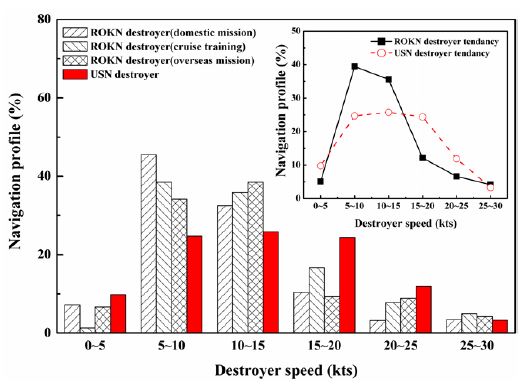
Figure 1 shows the survey results of the operation profile of three destroyers of ROK navy which performed domestic operation, overseas mission, and cruise training, respectively, in comparison with the operation profile of a U.S. Navy (USN) destroyer.
The ROKN destroyer, which has a full displacement of 5,500 tons, has advantages such as sufficient cargo and armed loading space, crew capacity (~ 310 personnel), and seaworthiness. It is a vessel type for various domestic and international missions. ROKN destroyers perform an average of 9–9.5 months for missions annually and have 2.5–3 months for repairs.
Referring to Figure 1, the USN destroyer operation profile shows that the range of 5 to 20 kts occupies approximately 75% of the total speed range, and the speed is evenly operated in that speed range. In contrast, the destroyer (average) of the ROK navy has an operation rate biased in the 5–10 kts and 10–15 kts ranges. In addition, the operation ratio in the speed range (15 to 20 kts) including the speed at which the economic efficiency of the diesel engine is maximized (hereinafter, economic speed) (80 to 90% of maximum continuous rating speed) is only 12%.
When constructing the electric propulsion system for the next destroyer type, the system can be optimized from the viewpoint of the vessel's economic efficiency by reflecting the operation profile of the actual vessels confirmed in Figure 1 in the process of selecting the power generators. The operation of the gas turbine generators that show a high fuel consumption rate and a low load must be rejected as much as possible in a range showing a high operation ratio, and the diesel engine generators must be operated under the most economical condition.
2.2 Configuration of the IFEP for the Republic of Korea Navy destroyer
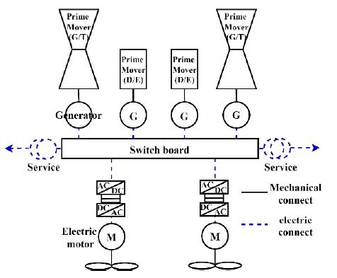
The object vessel is a fully electric propulsion vessel, consisting only of electric power cables and power generation prime movers connected to the distribution system, without a propulsion prime mover with axis dependencies. The power prime mover can be selected from diesel engines and gas turbines, and a gas turbine generator with high specific power is essential to generate the output required for the vessel's displacement and maximum speed of 30 kts. Figure 2 shows the basic configuration of the IFEP used on the UK navy Type-45 destroyer.
The arrangement of each component is flexible compared to the mechanical propulsion system, and the electric power generated by each prime mover is managed by the common distribution system without distinguishing between the left and right axes. In the IFEP system, diesel engine generators are responsible for low level power loads of approximately 3 MW or less, considering low specific power to produce high-level power, and are subject to considerable restrictions on weight and space. However, as they have the advantage of a significantly lower fuel consumption rate than gas turbine generators, diesel engine generators need to be mainly operated in the power load range showing a high operating rate.
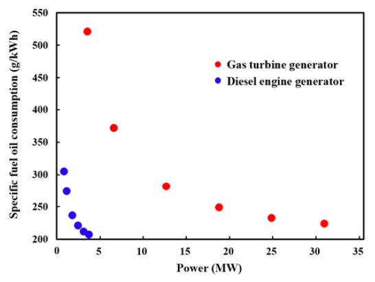
Figure 3 compares the fuel consumption of a GE LM-2500 G4 + gas turbine-powered generator, which is primarily used in vessels, with a MTU 20V 4000M diesel engine-powered generator.
The gas turbine generator can produce up to 30 MW, which is approximately 10 times the maximum power generation capacity of a diesel engine generator per unit, and the fuel consumption rate is from a minimum of 224 g/kWh to a maximum of 521 g/kWh. Diesel engine generators have a fuel consumption rate of at least 207 g/kWh to a maximum of 305 g/kWh within a load of up to approximately 3 MW. As both types of generators have an increase in the fuel consumption rate at a low load, optimizing the load sharing according to the required power so that the prime mover approaches the optimum load is the key of the method for maximizing the economic efficiency of IFEP.
3. Diesel engine generator configuration and operation strategy for electric-powered destroyer
3.1 Diesel engine generator configuration
There was a lot of debate about whether to increase the number of diesel engine generators to two or three in the IFEP vessel, but one can view the conclusion through the performance upgrade project of the UK navy Type 45 destroyer, which is a representative IFEP vessel. It is judged that three diesel engine generators are a practically advantageous combination over two diesel engine generators.
Since their introduction into service, the UK navy’s Type 45 destroyers have experienced ongoing problems with the reliability and resilience of their all-electric power and propulsion system [11]. That six destroyers lost power in the Persian Gulf because of warm water is a prime case [12]. The solution to the problems was a major diesel engine generator upgrade to increase the electrical generation capacity.
The ROK navy also paid attention to the limit that destroyers cannot exert speeds of 10 kts or more with diesel engine generators alone and the lessons learned from the operation of electric propulsion vessels by the UK's navy, and continued to study the composition quantity of diesel engine generators until recently.
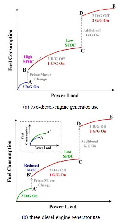
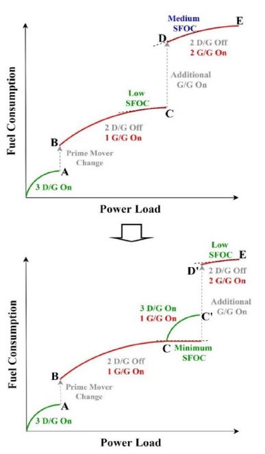
In this section, when configuring the IFEP of a 5,500 ton class destroyer with a full load using MTU20V 4000M diesel engine generator and GE LM-2500 G4 + gas turbine generator, in conditions where the number of diesel engine generators is two and three respectively, the changes in fuel oil consumption were studied. Moreover, the effect of additional configurations of the diesel engine generator was considered. In order to reflect the reality of the ROK navy's vessel operation, the operation profile discussed in Section 2.1 was applied, and the generator operation strategy was as shown in Figure 4, with two diesel engine generators operating and three diesel engine generators, respectively.
At a low-power load of the vessel, multiple diesel engine generators are used, and the diesel engine generators are stopped at a high-power load (Point A in Figure 4(a)), and the gas turbine generators are gradually operated sequentially (Point B and D in Figure 4(a)). In the process of stopping the diesel engine generators and switching the prime mover to one gas turbine generator (A → B), the diesel engine generators correspond to a 100% load condition and low specific fuel oil consumption (SFOC) condition (Point A in Figure 4(a)). However, gas turbine generators become uneconomical in operating conditions by moving to very high SFOC conditions under the load of approximately 20% (Point B in Figure 4(a)).
Therefore, when operating three diesel engine generators under the low-power load conditions of the vessel as shown in Figure 4(b), the power load range in charge of the diesel engine generators will increase by 1.5 times (A in Figure 4(a) → A' in Figure 4(b)). The point of the gas turbine generator start is later delayed (B in Figure 4(a) → B' in Figure 4(b)), and the gas turbine generator starts its first operation under an approximately 30% load condition (B' in Figure 4(b)) instead of the 20% load condition (B in Figure 4(a)). In this process, the SFOC of the gas turbine generator is significantly reduced (375 g/kWh → 310 g/kWh). Moreover, to make such positive factors lead to the effect of improving the actual fuel consumption of the vessel, the low load operation ratio must be high on the actual operation profile.
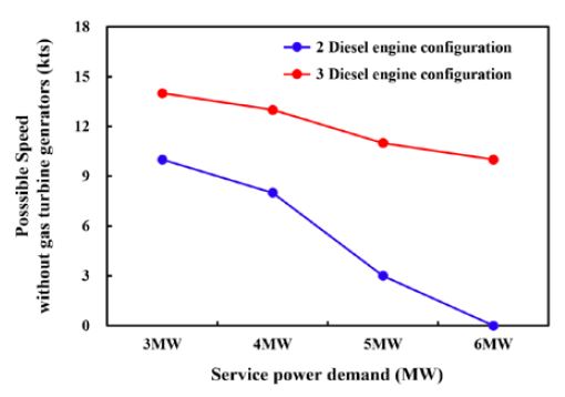
Figure 5 shows the maximum speed of the destroyer that can be guaranteed with only diesel engine generators under the conditions of two or three diesel engine generators when increasing the service power required for the operation of the weapon system and living of the crews from 3 MW to 6 MW. For the stable operation of the destroyer, 20% of the total required power is applied as the power margin, and the efficiencies of the generator and electric motor are equal, at 95%. The trends shown in Figure 5 are similar, as long as the values for both the power margin and the efficiency of the generator and electric motor do not change significantly.
The range of 5 to 15 kts, which is the main operating speed of the destroyer confirmed in Figure 1, is guaranteed under the condition of using three diesel engine generators, but is not possible under the condition of using two diesel engine generators. Considering the following issues, i.e., the increase of operation ratio in the range of 10 to 15 kts as ocean voyages increase, goal of the ROK navy to be the oceanic navy (long-distance voyage), and high-power use of future vessels for a large amount of weapon systems, it is not possible to achieve a speed of 10 to 15 kts with only two diesel engine generators under high service power conditions. So, a two-diesel-engine generator strategy is not suitable for future IFEP vessels.
Figure 6 shows the fuel consumption change for a year of the IFEP destroyer owing to the service power load condition when the current operation profile of ROKN destroyers (Figure 1) is substituted under the same conditions as the above calculation.
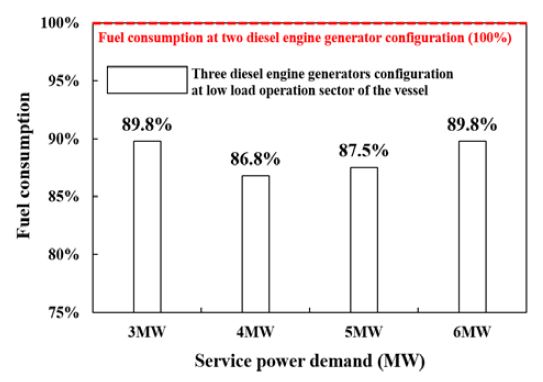
Fuel consumption comparison of the IFEP destroyer between two-diesel-engine generators and three-diesel-engine generators conditions
In the three-diesel-engine generators operation mode, a fuel saving effect of at least 10% to a maximum of 13% for the IFEP vessel was confirmed depending on the service power condition compared to the two-generators operation mode. However, a diesel engine generator is very heavy and huge, it is necessary to consider the weight and volume increase of the vessel. The MTU 20V4000M generator 1set is weight equivalent to approximately 40 tons, and the volume is estimated to be approximately 68 m3 by adding 20% of the space margin required for peripheral accessory installation and maintenance space.
The 10 to 13% of fuel that can be saved by operating three diesel engine generators is equivalent to approximately 95 to 123 tons and 109.2 to 141.4 m3 based on the fuel load capacity of the Chungmugong Yi Sunsin-class destroyer. So, it is possible to sufficiently offset the weight of 40 tons required for the additional installation of one diesel engine generator and the volume of 68 m3 required for installation and operation, and at the same time, it is possible to create a weight margin of a minimum of 45 tons to a maximum of 80 tons.
If the vessel does not need to carry as much fuel oil as the weight margin, the vessel could also consider the additional operation of a Korean vertical launching system (KVLS) 1 (launch pad + eight missile modules = 24.7 tons) set, or multiple Korean surface-to-surface missiles (KSSMs,) or a maritime operational helicopter. In addition, in the actual project for the ROKN destroyer, the increase in the initial cost and maintenance cost of the IFEP owing to the additional installation of a diesel engine generator and the weapon systems should be considered.
3.2 Diesel engine generator operation strategies
The operation strategy of the diesel engine generators in Figure 4 is to operate the diesel engine generators only in the low load power range of the object vessel. However, the diesel engine generators can be additionally operated when the required power of the vessel increases by more than the maximum load of one gas turbine generator (C in Figure 4), so that the start point of the secondary gas turbine (D in Figure 4) can be delayed backward (D → D' in Figure 7) to improve the economic efficiency of the IFEP. In the range where three diesel engine generators are additionally operated (C ~ C'), the primary gas turbine generator is operated under the maximum load and minimum SFOC conditions, and the secondary gas turbine generator does not need to be operated. After that, when the load of point C' or more is reached, the three diesel engine generators are stopped. The two gas turbine generators are then operated together under a relatively low SFOC condition with a load of approximately 60% and are operated up to point E, which maximizes the required power of the vessel. Such an operation strategy can improve the fuel saving effect by the actual operation profile of the vessel and improve the maintainability of the secondary gas turbine generator, but conversely reduce the maintainability of the three diesel engine generators and the operational convenience for the crews.
As the results of the three diesel engine generators’ additional operation instead of the secondary gas turbine generator, the fuel consumption reduction effect is only approximately .5 to 1%, depending on the service power load condition (Figure 8). The range where the diesel engine generator is additionally driven (C ~ C') is in speed from 22 to 26 kts on the vessel's actual operation profile. In addition, the total ratio in speed from 22 to 26 kts is just 5 to 6%. So, the reduced SFOC owing to the additional operation of diesel engine generators does not lead to a large fuel saving effect.
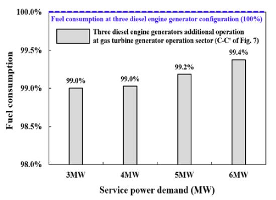
Fuel consumption change when three diesel engines’ additional operation at gas turbine generators’ operation sectors
Also, if the diesel engine generators are not driven in the relevant load range (C ~ C') and the secondary gas turbine generator is driven (D in Figure 7), the two gas turbine generators will start at approximately 50% load; however, the SFOC at 50% load of gas turbine generators is approximately 260 g/kWh, which already corresponds to a significantly improved SFOC. Therefore, it can be seen that the variation in the fuel consumption rate between both operating strategies is not relatively large, and the result leads to only a small percentage of improvement in the fuel consumption.
The effect of improving the fuel consumption by approximately 1% is a level that can be sufficiently ignored depending on the operating conditions of the vessel, considering the error range of ± 5% of the general SFOC. In addition, based on the actual engine operation experience of the naval combat vessel, the speed range in which the diesel engine generators are additionally driven (C ~ C') corresponds to the instantaneous load corresponding to the acceleration range for high-speed operation, not the main operation range of the vessel. So, the diesel engine generator usage time is expected to be very short in that range. The diesel engine is the engine requiring considerable attention in the process of starting and stopping, so additional starting and stopping for instantaneous operation is not a good option. Moreover, the disadvantage of additionally investing human resources for operating diesel engine generators cannot be ignored.
Therefore, the diesel engine generators need to be operated in the low load power range of the vessel and standing by as the redundancy to prepare for the unexpected failure of the gas turbine generator. In addition, operating all gas turbine generators from heavy load to maximum load is a more realistic and efficient operation method.
4. Conclusion
When configuring the IFEP system for a destroyer with a maximum speed of 30 kts and full displacement of 5,500 tons, the economic efficiency was considered from the viewpoint of the fuel consumption of the vessel, based on the quantity of diesel engine generators and diesel engine generator operation strategy. For the prime mover specifications of the diesel engine generator and gas turbine generator applied in the study process, the specifications of the MTU20V 4000M diesel engine and LM-2500 G4 + gas turbine were used, respectively. Importantly, the change in power load requirements was not a simple assumption, but an actual operation profile that was actually investigated over a year the Chungmugong Yi Sunsin-class destroyers.
The conclusions of this study can be summarized as follows:
- 1) Some navies operating IFEP vessels are considering adopting a plan to operate three diesel engine generators to ensure the power operation stability of the vessel.
- 2) In the three-diesel-engine generators operation mode for the object vessel used in the study, even if the power requirement for the weapon system and cabin increases sharply, it is possible to achieve the object vessel’s main operating speed of 10 to 15 kts.
- 3) In the three-diesel-engine generators operation mode, fuel consumption can be reduced by 10 to 13% (95 to 123 tons) compared to operating two diesel engine generators. By not carrying the fuel amount corresponding to the reduction, the weight and volume required for the additional installation of one diesel engine generator set (40 tons) can be sufficiently offset.
- 4) The fuel savings of approximately 45 to 83 tons, which is secured even if one set of diesel engine generator is additionally installed, can be replaced with the tonnage of the weapon system. In this case, one set of KVLS, a large number of KSSMs, and one additional maritime operation helicopter can be considered.
- 5) When the three diesel engine generators are additionally operated in the medium- to maximum-load range where the gas turbine generators are operated, the low-load operation of the gas turbine generator is reduced. So, the fuel consumption can be reduced. However, considering the specifications of the object vessel and actual operation profile conditions, there was only a 1% fuel consumption reduction.
- 6) Therefore, the diesel engine generators need to be operated in the low-load power range of the vessel and standing by as the redundancy to prepare for the unexpected failure of the gas turbine generator. In addition, operating all gas turbine generators from heavy load to maximum load is a more realistic and efficient operation method.
Abbreviations
| D/G : | Diesel engine generator |
| G/G : | Gas turbine generator |
| IFEP : | Integrated fully electric propulsion |
| KDDX : | Korean destroyer experimental |
| KVLS : | Korean vertical launching system |
| KSSM : | Korean surface to surface missile |
Acknowledgments
This study was supported by the 2022 Academic Research Project of the Naval Institute for Ocean Research of the Republic of Korea Naval Academy.
Author Contributions
Conceptualization, H. -M. Baek; Methodology, H. -M. Baek, S. Kim, and H. Lee; Formal Analysis, H. -M. Baek, S. Kim, and H. Lee; Investigation, S. Kim and H. Lee; Writing-Original Draft Preparation, H. -M. Baek; Writing-Review & Editing, H. Lee.
References
- J. Schuddebeurs, De-risking Integrated Full Electric Propulsion (IFEP) Vessels using Advanced Modelling and Simulation Techniques, Ph.D. Dissertation, Institute for Energy and Environment Department of Electronic and Electrical Engineering University of Strathclyde, November, 2014.
- P. J. Norman, C. D. Booth, J. D. Schuddebeurs, G. M. Burt, J. R. Mcdonald, J. M. Apsley, M. Barnes, A. C. Smith, S. Williamson, E. Tsoudis, P. Piludis, and R. Singh, “Integrated electrical and mechanical modelling of integrated full-electric-propulsion systems,” University of Strathclyde, UK, [Online]. https://strathprints.strath.ac.uk/37692/1/int.pdf, .
-
D. -W. Jung, J. -S. Sim, S. -Y. Kim, and I. -Y. Chung, “Optical design of generation system of electric ship considering fuel cost analysis and economic analysis with energy storage system application,” The transactions of the Korean institute of electrical engineers, vol. 70, no. 8. pp. 1156-1166, 2021 (in Korean).
[https://doi.org/10.5370/KIEE.2021.70.8.1156]

- S. -Y. Kim, “Design of shipboard energy storage system and operation for voltage/frequency compensation in naval integrated power system”, Ph.D. Dissertation, Seoul national university, 2014.
- N. Doerry and K. Moniri, “Specifications and standards for the electric warship,” U. S. Naval sea system command, Washington DC, USA.
- Korean Register, Naval vessel rules- chapter 4. Electric devices – phase 1. Electric propulsion system, 2013 (in Korean).
-
H. -M. Lee and B. -J. Cho, “Analysis of development trend for the integrated power system of naval vessels to perform the high-power and energy mission load platform,” Journal of the Korean Society of Marine Engineering, vol. 35, no. 6, pp. 796-801, 2011 (in Korean).
[https://doi.org/10.5916/jkosme.2011.35.6.796]

- Rolls-royce, Power surge - increasing onboard electrical power for the US navy’s DDG-51 destroyers, https://www.rolls-royce.com/media/our-stories/discover/2017/power-surge-ag9160.aspx, , Accessed May 12, 2022.
- B. H. Gully, “Hybrid Powertrain Performance Analysis for Naval and Commercial Ocean-Going Vessels”, Ph. D. dissertation, The University of Texas at Austin, USA, 2012. Available at http://hdl.handle.net/2152/ETD-UT-2012-08-6270, .
- The Royal Institution of Naval Architects, Type 45 to get third diesel generator to overcome problems, https://www.rina.org.uk/Type_45_to_get_third_diesel_generator_to_overcome_problems.html, , Accessed May 12, 2022.
- B. Britton, CNN, Britain’s Royal Navy warships are breaking down because sea is too hot, https://edition.cnn.com/2016/06/09/europe/britain-royal-navy-warships/index.html, , Updated June 10, 2016, Accessed May 12, 2022.


