Remaining life prediction algorithms of electric motors for exhaust gas recirculation blower systems
Copyright ⓒ The Korean Society of Marine Engineering
This is an Open Access article distributed under the terms of the Creative Commons Attribution Non-Commercial License (http://creativecommons.org/licenses/by-nc/3.0), which permits unrestricted non-commercial use, distribution, and reproduction in any medium, provided the original work is properly cited.
Abstract
The remaining life prediction of the electric motors is required for stable operation of the EGR systems and selection of an appropriate maintenance period due to the electric motor accounts for 80% of the electric loads in the EGR blower system. Therefore, this paper proposes the algorithms for predicting the remaining life of bearings and windings, which are the main causes of electric motor failures. The equations are presented for predicting the remaining life using the speed and temperature of the electric motor, which are factors that affect the lifespan of the bearings and windings of the electric motor. The EGR blower system is modeled and simulated with the power electronics simulation program PSIM using the data obtained through the thermal analysis of the electric motor according to the load change of the EGR blower. The validity of the remaining life prediction algorithm according to the load change of the EGR blower is verified using the implemented simulation.
Keywords:
Electric motor, Exhaust gas recirculation, Information communication technology, Maintenance, Remaining life prediction algorithm1. Introduction
The International Maritime Organization (IMO) has revised the nitrogen oxide (NOx) regulation of all ships ordered from 2016 to Tier II for diesel engines exceeding 130kW for the regulated areas of ship exhaust gas in North America and the Caribbean. Based on Tier I standard, about 15-20% of NOx emission reduction standard is set to Tier III, and other regions limit the reduction of about 80% NOx emission based on Tier I [1]. The research on exhaust post-treatment technology as a technology for reducing NOx is being actively conducted due to these strengthened regulations, A representative exhaust post-treatment technology is a system that injects a reducing agent into the exhaust gas with a selective catalytic reduction (SCR) and passes it through the catalyst layer to carry out the NOx reduction reaction at 250 ~ 400 ℃ [2]. SCR has disadvantages such as increased weight, heat and pressure drop of the engine, large volumetric space requirement, and high cost for maintenance [3]. Exhaust gas recirculation (EGR), which can replace these problems, recirculates a part of exhaust gas discharged from the engine to the intake air to lower the oxygen concentration in the combustion chamber and increase the ratio of inert gas to suppress the temperature rise of combustion gas, and thermal NOx formation reaction. Although the initial installation cost is higher than the SCR, the EGR has a shorter initial investment recovery period due to the low maintenance cost, and has been widely applied to ships recently [4]-[6].
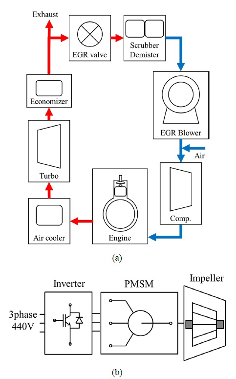
Figure 1 shows the configuration diagram of the EGR system. The EGR system consists of a main loop and an EGR loop. In the main loop, clean air is injected into the engine through a compressor and a cooler, and the EGR loop is composed of a scooter, a demister, and an EGR blower system at the exhaust port of the engine to recirculate the exhaust gas of the engine. The EGR blower system serves to increase the exhaust gas pressure lower than the scavenging air pressure [7]. The motor drive system consists of a motor and an inverter to control the speed of the motor to drive the impeller in the EGR blower. Since the EGR blower system is a key element for reducing NOx in the EGR system, continuous monitoring is required for stable operation.
With the recent 4th industrial revolution, information communication technology (ICT) is applied to various systems to predict real-time monitoring and maintenance time. By applying ICT to the EGR system, it is possible to accelerate the recovery of the initial investment cost through efficient maintenance [8]. It is essential to predict the remaining life of the motor for the stable operation of the EGR system due to the motor accounts for 80% of the electric load in the EGR blower system. The causes of motor failure are bearing failure 41%, stator winding failure 37% and other 22% [9][10].
Predictive maintenance techniques for the non-intrusive management of electric motors have been the subject of many research papers in recent years. Multi-scale Extended Kalman Filter (EKF) was employed for this purpose using the data of input current and output velocity measured during the life test of the motor [11]. [12] studied the remaining lifetime estimation of BLDC motors considering voltage drop and attention-based neural networks. [13] used the exponential degradation model to predict the remaining useful life of the motor with improved accuracy. Conventional studies are based on the degradation of electrical performance and fault detection using digital filters. Therefore, this paper proposes a remaining life prediction algorithm for bearings and windings, which are the main causes of motor failure. The factors affecting the lifespan of bearings and windings are the speed and temperature of the motor. In addition, the EGR blower system is modeled using the power electronics simulation program PSIM using the data obtained through the thermal analysis of the motor according to the load change of the EGR blower to implement the simulation. The validity of the remaining life prediction algorithm according to the load change of the EGR blower is verified using the implemented simulation.
2. Performance Analysis of EGR Blower System
2.1 Performance Analysis of EGR Blower
The EGR blower adjusts the speed according to the air flow to maintain a constant pressure. The air flow of EGR can be expressed as a velocity function as follows [14].
| (1) |
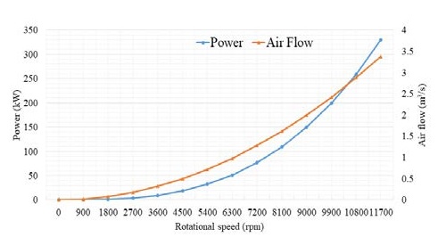
Here, KB is the blower constant, and n is revolutions per minute of the motor. Figure 2 shows the required output curve of the motor according to the air flow for each speed of the EGR blower.
As shown in Table 1, when the air flow is 2 m3/s at the blower speed of 9000 rpm while maintaining the constant pressure of 3.5 bar, 150kW of output is required, and the required output power PL of the motor according to the blower speed can be expressed as follows [14].
| (2) |
2.2 Performance Analysis of Motor
Based on the specifications of the selected EGR blower system, the required rated torque of the EGR blower driving motor is 159 Nm. Using the motor design program MOTORCAD, the electromagnetic field analysis results and thermal analysis results according to load variations were derived as shown in Figure 3. The type of the motor is a permanent magnet synchronous motor, and the rated current was selected as 340 A by considering 9% of the line to line voltage margin of the input voltage of 440 V to enable over-speed driving of 1.25 times the rated speed during classification. The required torque is satisfied as the output torque of the motor is 162 Nm as shown in Figure 3(a).
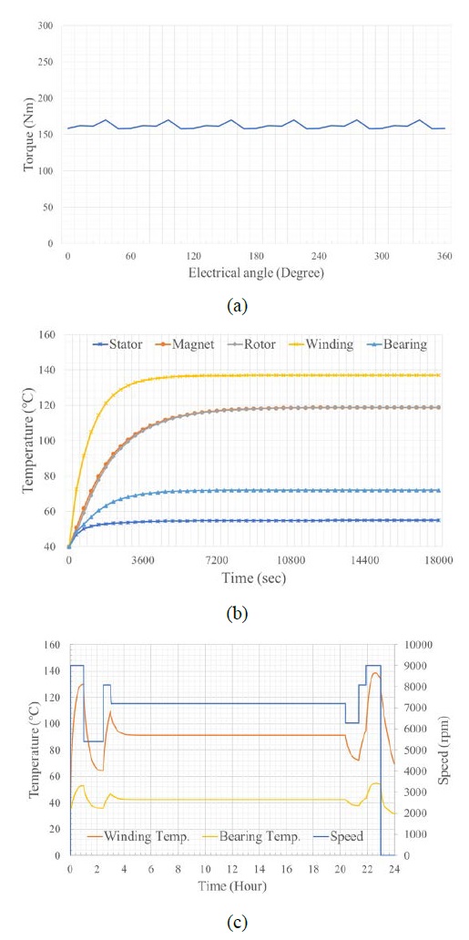
Electromagnetic field analysis and thermal analysis results (a) Output torque (b) Temperature saturation curves (c) Temperature curves according to load variation
At the rated speed of 9000 rpm, with the required torque of 159 Nm applied, the temperature saturation time is about 3 hours as shown in Figure 3(b), and the highest temperature point is about 137 ℃ with the winding.
Since the change in the air flow of the EGR blower varies depending on the driving state of the engine, a thermal analysis was performed as shown in Figure 3(c). It can be seen that the temperature of the bearing and winding changes as the speed is adjusted according to the required quantity and the load of the motor increases. The derived results can be applied to simulation modeling for verification of the remaining life prediction algorithm of the motor.
3. Remaining Life Prediction Algorithm
3.1 Remaining Life Prediction Algorithm of Bearing
The bearings applied to the designed motor are ball bearings, and the rated fatigue life can be expressed as follows [15][16].
| (3) |
Here, C is the basic dynamic load, P is the equivalent applied load, and fh is the fatigue life coefficient. Bearings have different lifespan according to speed change, so they can be expressed as fatigue life coefficient fh and speed coefficient fn respectively as follows
| (4) |
| (5) |
When the bearing is used at high temperature, the hardness of the bearing decreases and the fatigue life is lowered than at room temperature. The basic dynamic load rating Ct considering the temperature coefficient according to the temperature coefficient can be expressed as follows.
| (6) |
Here, ft is the temperature coefficient. The value of the temperature coefficient according to the temperature depends on the selected bearing. The bearing load is the relationship between the theoretically calculated load and the load factor considering the operating environment and can be expressed as follows:
| (7) |
| (8) |
Here, Fr and Fa are the radial and axial loads acting on the bearing, Frc and Fac are the theoretical calculated radial and axial loads, and fw are the load coefficients. Since the bearings of the motor are arranged on the drive end (DE) and the non-drive end (NDE), respectively, the position of the bearing is determined according to the rotation axis of the motor, and the load is distributed according to the center of rotation shaft gravity. The radial loads of the bearings on the DE and the NDE can be expressed as follows
| (9) |
| (10) |
Here, a is the distance from the DE bearing to the center of gravity, b is the distance from the NDE bearing to the center of gravity, and c is the distance between the bearings.
As for the load of the bearings, a composite load is generated in which the radial load and the axial load are applied at the same time. Based on the rotational and load conditions in the calculation of the fatigue life of the bearing, the size is constant so that the lifespan is the same as the actual fatigue life. The equivalent load P passing through the center of the bearing can be expressed as follows
| (11) |
Here, X is the radial load factor, and Y is the axial load factor. These factors are determined according to the selected bearing specification. Table 2 shows the rotation shaft specifications of the designed motor.
Table 3 shows the coefficient values selected for the rated speed and the basic rated life using Equations (3) to (11) when continuously driven at a rated speed of 9000 rpm and a bearing temperature of 72 ℃. Since the temperature coefficient of the bearing decreases when it is over 150 ℃, the saturation temperature of the motor is less than 72 ℃, therefore the temperature coefficient is constant at 1.
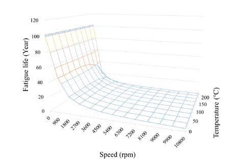
As the driving speed of the motor in the EGR blower system is adjusted to maintain a constant pressure, real-time speed and temperature information are acquired at a constant cycle and the basic rated life is calculated at every moment to accurately predict the remaining life. The speed coefficient and temperature coefficient were obtained using the Equations (3) to (11) at 25 °C intervals within the temperature range of 0~200 °C and at 900 rpm intervals within the speed range of 0~10800 rpm. Using these values, fatigue life data was derived as a lookup table. The three-dimensional curve of the fatigue life according to the speed and temperature of the bearing is shown in Figure 4.
The equation for the prediction of the remaining life using the speed and temperature data of the bearing can be expressed as follows:
| (12) |
Here, Li(B) is the initial value of the fatigue life of the bearing, and LRT(B) is the fatigue life value that is outputted by inputting real-time data and composing a three-dimensional curve of the fatigue life according to the speed and temperature of the bearing as a lookup table. The amount of reduction is calculated by calculating and integrating the fatigue life according to real-time data. After that, this value can be subtracted from the initial fatigue life Li to finally calculate the remaining life.
3.2 Remaining Life Prediction Algorithm of Winding
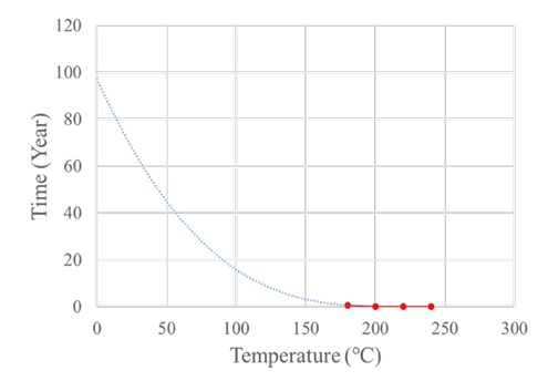
The winding insulation grade of the designed motor is F. The ASTM D1830 standard suggests the required life time according to the insulation grade and temperature. The required life time was selected as a criterion for the fatigue life. Table 4 shows the required life time according to the winding temperature of ASTM D1830 [17].
Since the saturation temperature of the designed motor is 137 ℃, in order to derive the required life time according to the load of the motor in Table 4, a trend line can be derived as shown in Figure 5 through trend line analysis.
The equation of the derived trend line can be expressed as a function of temperature as follows.
| (13) |
Here, TW is the real-time temperature of the motor. The prediction of the remaining life of the winding can be obtained with the same formula as in Equation (12).
| (14) |
Here, Li(W) is the initial value of the remaining life of the winding, and Tl is the remaining life value that is outputted by inputting real-time data and composing the trend line value according to the temperature of the winding. Assuming that the motor speed is continuously driven at 9000 rpm and the winding temperature is 137 ℃, the life time is calculated as 5.27 years.
4. Simulation
In order to prove the validity of the proposed algorithm for predicting the remaining life of bearings and windings of the motor, the EGR blower system was modeled using the power electronics simulation PSIM.
Figure 6(a) shows a simplified model of the EGR blower system. The model of the motor drive system requires a sampling time of several μs in the simulation because the control cycle is very short due to the inverter operating at several to several tens of kHz. However, the operating time is at least one day to several years due to the EGR blower system has to consider the load fluctuation and temperature change according to the speed of the motor, therefore the model of the motor drive system was simplified.
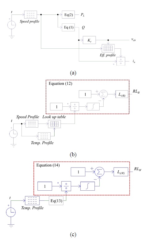
Models of EGR blower system (a) EGR blower system (b) Model of bearing remaining life prediction algorithm (c) Model of winding remaining life prediction algorithm
The torque can be calculated due to the load of the EGR blower is proportional to the third power of the speed [11]. An efficiency map can be derived through electromagnetic field analysis in consideration of speed and load torque. Using the derived efficiency map, line to line voltage and phase current are calculated according to the calculated load according to the speed profile. The air flow and power of the blower are calculated using Equation (1) and (2). The temperature of the motor according to the speed change was composed of a temperature profile based on thermal analysis.
Figure 6(b) and (c) show the algorithm model for predicting the remaining life of the bearings and windings of the motor. The bearing remaining life prediction algorithm model receives the speed profile and the temperature profile from a lookup table using the three-dimensional fatigue life curve data according to the speed and temperature of the bearing as inputs, and calculates the real-time fatigue life value. The value is substituted into Equation (12) to calculate the residual life value of the bearing. In the winding remaining life prediction algorithm model, the output value of the temperature profile is substituted in Equation (12) to derive the winding life value of the winding.
Figure 7 shows the simulation results of the bearing and winding remaining life prediction algorithm when the EGR blower system is continuously driven at a speed of 9000 rpm to supply 2 m3/s while maintaining the pressure of 3.5 bar. It was assumed that the bearing and winding temperatures were maintained at the saturation temperatures of 72 ℃ and 137 ℃.
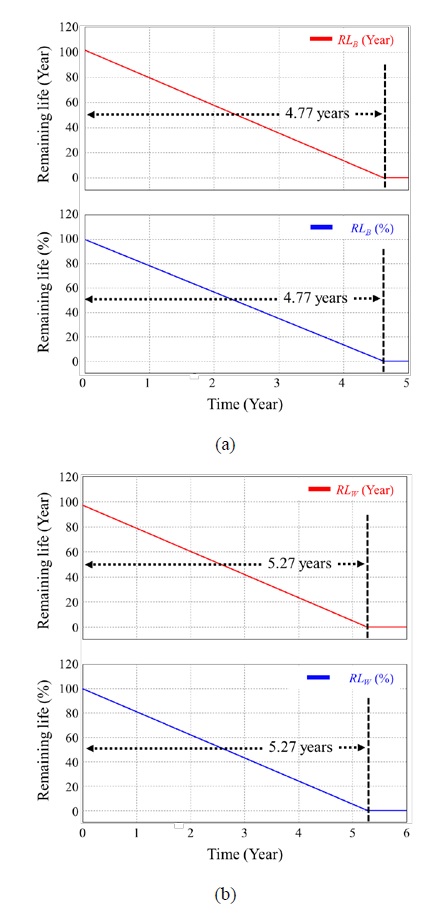
Simulation results of remaining life predictive algorithm when continuously driven at a rated speed 9000 rpm (a) Bearing remaining life (b) Winding remaining life
The remaining life was expressed as years and percentage. The percentage is calculated as the ratio of the initial remaining life to the current remaining life. It can be seen that the remaining life of the bearing reaches zero at 4.77 years. This value is the same as the rated fatigue life calculated by Equation (3) to (11). The remaining life of the winding reaches zero at 5.27 years and is the same as the remaining life using Equation (13). As a result, the validity of the operation of the proposed algorithm was verified.
Figure 8 shows the simulation results of the bearing life expectancy prediction algorithm according to load fluctuations during one day of the EGR blower system. Figure 8(a) shows the response of the EGR blower system model according to the load change. It can be seen that the flow rate, line voltage, and phase current change according to the speed.

Simulation results of the remaining life prediction algorithm according to the load fluctuations during the one day of the EGR blower system (a) Responses of EGR blower system model (b) Bearing remaining life (c) Winding remaining life
In Figure 8(a) and (b), the initial remaining life of the bearing is 101.68 years, and at the end of one day, the remaining life is 101.637 years, a decrease of 0.045%. In the case of windings, the initial lifespan was reduced by 0.015% from 97.077 years to 97.0635 years. As a result, we confirmed the operation verification of the algorithm that can predict the remaining life through the rotational speed of the motor and the temperature of the bearing and winding according to the load change of the EGR blower system.
5. Conclusion
In the EGR blower system for reducing nitrogen oxide emissions of ships, it is necessary to predict the remaining life of bearings and windings which are the main causes of motor failure to determine the stable operation of the motor. Therefore, in this paper, the remaining life prediction algorithm was proposed based on the real-time speed and temperature data according to the load change of the motor of the EGR blower system. The proposed algorithm verified the response characteristics of the system through simplified modeling of the EGR blower system for long-term simulation, and the validity of the proposed algorithm was verified through the simulation results applying the remaining life prediction algorithm model. Using the verified algorithm, the profile that considers the load fluctuation of the EGR blower system during one day was applied to the EGR blower system model to confirm the verification of the operation of the algorithm according to the speed and temperature change of bearings and windings.
Acknowledgments
This study was supported by a grant from the Korea Industrial Complex Corp. (KICOX. No. PBS21005).
Author Contributions
Conceptualization, S. -A. Kim; Methodology, S. -A. Kim; Software, S. -A. Kim; Validation, S. -A. Kim; Formal Analysis, S. -A. Kim; Investigation, S. -A. Kim; Resources, S. -A. Kim; Data Curation, S. -A. Kim; Writing—Original Draft Preparation, S. -A. Kim; Writing—Review & Editing, S. -A. Kim; Supervision, S. -A. Kim; Funding Acquisition, S. -A. Kim.
References
-
R. Verschaeren, W. Schaepdryver, T. Serruys, M. Bastiaen, L. Vervaeke, and S. Verhelst, “Experimental study of NOx reduction on a medium speed heavy duty diesel engine by the application of EGR (Exhaust Gas Recirculation) and Miller timing,” Energy, vol. 76, pp. 614-621, 2014.
[https://doi.org/10.1016/j.energy.2014.08.059]

- G. Y. Jeong, B. J. Im and S. S. Lee. “Green Ship SCR System Technology Development Status-SCR System Catalyst Technology Trend,” Korea Institute of Materials Science, vol. 24, no. 2, pp. 38-46, 2012 (in Korean).
- S. D. Rudrabhate, and S. V. Chaitanya, “Comparison between EGR & SCR Technologies,” International Conference on Ideas, Impact and Innovation in Mechanical Engineering (ICIIIME) of Conference Proceeding, pp. 856–861, 2017, June.
-
G. Zamboni and M. Capobianco, “Influence of high and low Pressure EGR and VGT control on in-cylinder pressure diagrams and rate of heat release in an automotive turbocharged diesel engine,” Applied Thermal Engineering, vol. 51, no. 1-2, pp. 586–596, 2013.
[https://doi.org/10.1016/j.applthermaleng.2012.09.040]

- G. Patrianakos, M. Kostoglou, A. Konstandopoulos, A. Imren, I. Denbratt, R. Palacin, C. Beatrice, N. Rispoli, and G. Di Blasio, Emission Reduction Technologies for the Future Low Emission Rail Diesel Engines: EGR vs SCR, Technical Paper 2013-24-0087, SAE International, USA, 2013.
-
F. C. Buenaventura, E. Witrant, V. Talon, and L. Dugard, “Air fraction and EGR proportion control for dual loop EGR diesel engines,” Ingenieria Y Universidad, vol. 19, no. 1, pp. 115-133, 2015.
[https://doi.org/10.11144/Javeriana.iyu19-1.aegr]

-
Z. Wang, S. Zhou, Y. Feng, and Y. Zhu, “Research of NOx reduction on a low speed two stroke marine diesel engine by using EGR (Exhaust Gas Recirculation)-CB (Cylinder Bypass) and EGB (Exhaust Gas Bypass),” International Journal of Hydrogen Energy, vol. 42, no. 30, pp. 19337-19345, 2017.
[https://doi.org/10.1016/j.ijhydene.2017.06.009]

-
A. Rojko, P. Bauer, P. Prochazka, I. Pazdera, and O. Vitek, “Development and experience with ICT based education in sustainably energy,” In 2015 IEEE International Conference on Industrial Technology (ICIT), pp. 3264-3269, 2015.
[https://doi.org/10.1109/ICIT.2015.7125581]

-
B. Lu, D. B. Durocher, and P. Stemper, “Predictive maintenance techniques,” IEEE Industry Applications Magazine, vol. 15, no. 6, pp. 52-60, 2009.
[https://doi.org/10.1109/MIAS.2009.934444]

-
K. Toni, M. Slobodan, and B. Aleksandar, “Detection of turn to turn faults in stator winding with axial magnetic flux in induction motors,” In 2007 IEEE International Electric Machines & Drives Conference, pp. 826-829, 2007.
[https://doi.org/10.1109/IEMDC.2007.382775]

-
Y. Yun, J. Lee, H. -S. Oh, and J. H. Choi, “Remaining useful life prediction of reaction wheel motor in satellites,” JMST Advances, vol. 1, no.3, pp. 219-226, 2019.
[https://doi.org/10.1007/s42791-019-00020-5]

-
T. A. Shifat and H. Jang-Wook, “Remaining useful life estimation of BLDC motor considering voltage degradation and attention-based neural network,” IEEE Access, vol. 8, pp. 168414-168428, 2020.
[https://doi.org/10.1109/ACCESS.2020.3023335]

-
A. Banerjee, S. K. Gupta, C. Putcha, “Degradation data–driven analysis for estimation of the remaining useful life of a motor,” ASCE-ASME Journal of Risk and Uncertainty in Engineering Systems, Part A: Civil Engineering, vol. 7, no. 2, 2021.
[https://doi.org/10.1061/AJRUA6.0001114]

-
S. A. Kim and K. P. Hong, “Analysis and experimental verification of a variable speed turbo air centrifugal compressor system for energy saving,” Energies, vol. 14, no. 4, pp. 1208, 2021.
[https://doi.org/10.3390/en14041208]

-
S. P. Lee, “Bearing life evaluation of automotive wheel bearing considering operation loading and rotation speed,” Transactions of the Korean Society of Mechanical Engineers A, vol. 40, no. 6, pp. 595-602, 2016 (in Korean).
[https://doi.org/10.3795/KSME-A.2016.40.6.595]

-
C. Sun, Z. Zhang, and Z. He, “Research on bearing life prediction based on support vector machine and its application,” Journal of Physics: Conference Series, vol. 305, no. 1, p. 012028, 2011.
[https://doi.org/10.1088/1742-6596/305/1/012028]

-
E. C. Johnson, “A new concept in mica paper insulation,” 1965 Sixth Electrical Insulation Conference, pp. 98-101, 1965.
[https://doi.org/10.1109/EIC.1965.7461193]


