Magnetic induction communication using toroidal helix coil
Copyright ⓒ The Korean Society of Marine Engineering
This is an Open Access article distributed under the terms of the Creative Commons Attribution Non-Commercial License (http://creativecommons.org/licenses/by-nc/3.0), which permits unrestricted non-commercial use, distribution, and reproduction in any medium, provided the original work is properly cited.
Abstract
In a wireless communication environment, a metal medium is one of the main causes of increase in the path loss of electromagnetic (EM) waves. Even well-established EM communication techniques do not perform well because of their high signal attenuation. Magnetic induction (MI) is a promising technology in challenging wireless environments, such as metal structures or underground. The performance of MI transmitters and receivers is critical for achieving both channel connectivity and energy efficiency. In this study, we propose a toroidal helix coil as an MI antenna and provide EM characteristics by analyzing it using COMSOL. Based on the analysis, a pair of coils with 20 windings were manually fabricated, and MI communication experiments were performed using them. As a result, an average bandwidth of 7 Mbps was obtained by applying the proposed MI coil in a wireless environment with a 5 mm thick metal plate.
Keywords:
Magnetic induction communication, Magnetic field communication, Helix coil, Toroidal coil, Eddy current1. Introduction
As an extension of the Internet of Things (IoT), wireless sensor networks offer a variety of new applications. However, there are still many hostile and complex environments that cannot be addressed using conventional radio frequency techniques, such as underground, underwater, oil storage, nuclear power plants, pipelines, tunnels, and concrete buildings. Magnetic induction (MI) is a type of wireless communication method that uses a time-varying magnetic field, allowing for short-range wireless communication in various areas, including the extreme environments mentioned above. When electromagnetic (EM) waves pass through obstacles such as metals or liquids, the magnetic field can be distorted but not completely blocked, so its strength can remain greater than that of the electric field. Therefore, MI is being evaluated as a next-generation short-range wireless communication method that overcomes the problems of EM waves being sensitive to fading, reflection, and environmental conditions [1].
In [2], helix coils were used to analyze the MI channel characteristics in underground wireless sensor networks. In addition, a magnetic field-guided waveguide for underground radio communication was proposed to reduce path loss and extend the transmission range. In [3], a platform for performing MI communication were built to measure the transmission distance using magnetic field-guided signals. In [4], the authors presented alternatives to the well-known problems of hydroacoustic communication, namely, high propagation delay, very low data rates, and environment-dependent channel behavior. The research results, such as the channel model and positioning of magnetic field-based underwater communication, are noteworthy. In [5], the effects of two winding types, spiral and helix, on power transfer efficiency were studied, and the results showed that the magnetic coupling between helix coils was stronger than that between spiral coils.
The MI transmitter and receiver are generally modeled as the primary and secondary coils of a transformer, and both the multiturn coils operate in a tuned resonance state. The winding types of the coils can be classified into helical and spiral. As the transmission distance (d) increases, the magnetic field strength falls off much faster (1/d3 ) than that of EM waves (1/d) in free space [6].
In MI systems with high magnetic field attenuation, the coupling efficiency between the transmitting and receiving coils is very important. Their performance is critical for achieving better channel connectivity and high energy efficiency. In this study, a toroidal helix coil were proposed as an MI antenna. The coil was applied to a communication environment with a metal wall, and its EM properties were analyzed using COMSOL simulation software. Based on the analysis, a pair of coils with 20 windings were manually fabricated and MI communication experiments were performed using them.
2. Design and Numerical Analysis
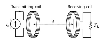
In MI communication, transmission and reception are accomplished using two wire coils, as shown in Figure 1. d is the transmission distance between the two coils. The magnetic field associated with EM induction usually arises from an electromagnet in which the current changes. Since the amplitude of the current changes continuously at a constant frequency, the magnitude of the magnetic field changes in the same manner. Periodic fluctuations in these amplitudes induce currents with the same frequency in the receiving coil. Regardless of how small the transmitting coil is, it creates a time-varying magnetic field, so there is no frequency limiting the operation of the receiver. This is different from the dipole antenna used in most EM wave-based wireless communication systems [7]. MI coupling is possible when a magnetic flux is generated in the coil, even if the frequency of the signal is in the MHz band. This means that a small coil antenna can be used to emit signals at a lower frequency than EM waves. Because the operating frequency of the coil can be predicted, MHz bandwidth can be realized while maintaining channel quality even in MI communication.
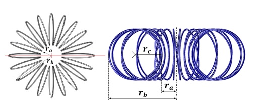
To study the magnetic properties of the toroidal helix coil, a finite element coil model is created, as shown in Figure 2. ra and rb are the inner and outer radii of the toroidal coil, respectively, and rc is the radius of the helix coil.
The magnetic field generated when an alternating current i0 is applied to one end of the coil is expressed by Equation (1).
| (1) |
where μ0 is the magnetic field constant of 4π × 10−7N/A2, μr is the relative permeability, and N is the number of turns of the coil. ra + rc is the radius of the Amperian loop inside the coil.
The magnetic field at any location outside the coil is given by Equation (2) [7].
| (2) |
The magnetic field is inversely proportional to the cube of the transmission distance.
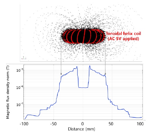
The parameters of the finite element model of the coil used for COMSOL analysis are listed in Table 1. The magnetic field distribution and magnetic flux density profile when an AC voltage of 5 V is applied to the coil are shown in Figure 3. All wire loops that make up the helix contribute to strengthening the magnetic flux in the same direction inside the toroid; thus, the magnetic flux density have a maximum value of 10 µT. On the other hand, a magnetic field is formed outside the coil in the direction of the pole. At the center of the coil, the magnetic field generated by the adjacent winding is reinforced in the same direction such that the magnetic flux density is maintained at 1 µT.
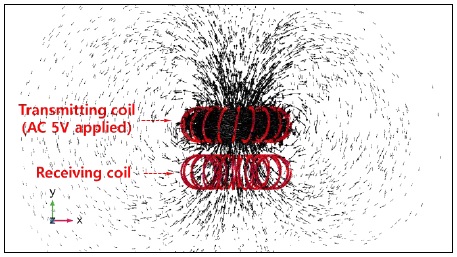
Figure 4 shows the magnetic field distribution between the transmitting coil and receiving coil. Although the two coils are electrically insulated, they are coupled by a magnetic field and therefore operate according to Faraday's law of induction. The centers of the two coils are aligned to face each other in parallel so that the magnetic field generated in the transmitting coil passes through the center of the receiving coil as much as possible.
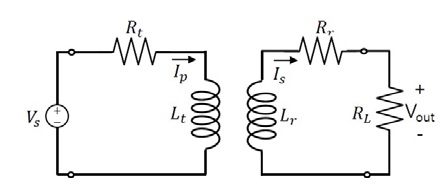
The electrical equivalent circuit of the MI transceiver is shown in Figure 5. Here, Rt and Rr are the intrinsic resistances of the transmitting and receiving coils, respectively; Vs and Vout are the AC input source and load output voltages, respectively; Ip and Is are the primary and secondary currents, respectively; and RL is the load resistance.
Input signal of the transmitting coil is a sinusoidal voltage with a peak voltage of 5 V and frequency of 1 MHz. The numerically obtained output voltage waveform when the distance between the two coils is 10 mm and the load resistance is 100 Ω is shown in Figure 6. The ratio of input to output signal is -56 dB.
In free space, magnetic fields decay more than 10 times faster than electric fields; therefore, the application models for MI communication are very limited. However, in environments with metal walls, which cause significant attenuation of radio signals, MI communication may be considered. The energy of the EM waves absorbed in an arbitrary medium is expressed as a function of permittivity, permeability, and electrical conductivity, as shown in Equation (3) [8].
| (3) |
where σ is the electrical conductivity, ω is the angular frequency of the wave, ε0 is the permittivity in vacuum, is the loss term of the non-complex dielectric constant, and is the loss term of the non-complex permeability. The absorption of an electric field (E) in a metal is much greater than that of a magnetic field (H), because of its high electrical conductivity.
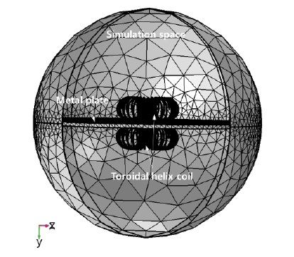
Figure 7 shows the COMSOL model for simulating the electromagnetic properties of an MI coil separated by a metal plate, which is an alloy steel AISI-4340 containing nickel-chromium-molybdenum. Its relative permittivity and relative permeability values were 1, but its electrical conductivity is 4.032×10⁶ S/m. The thickness of the plate is set to 5 mm.
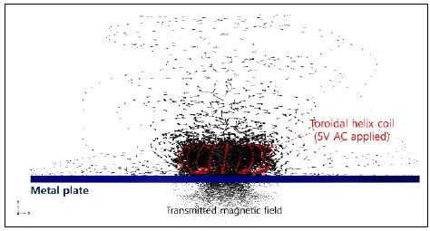
Figure 8 shows the simulation results in which the magnetic field generated by an MI coil is affected by the metal plate. The magnetic flux is concentrated nearly uniformly in the center of the coil. The outside field differs from the results in Figure 4 because it is distorted and scattered by the metal plate. However, because a partially transmitted magnetic field appears on the opposite side, MI communication can be made possible by placing the receiving coil at that side.
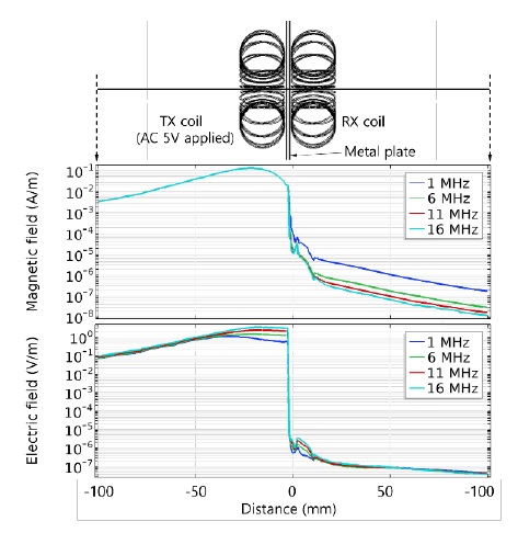
The magnetic and electric fields distributed along the axis passing through the center of the coil are shown in Figure 9. A sinusoidal wave with a peak voltage of 5 V and frequency of 1 MHz was applied to the transmitting coil. As the magnetic field passed through the metal plate, its strength decreased by 103 times. However, the electric field is reduced by a factor of 106 and is almost blocked. Communication connectivity between the inside and outside of the metal structure enabled inductive communication by the magnetic field.
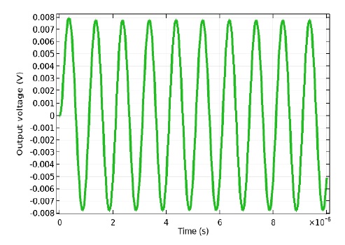
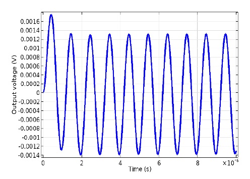
Figure 10 shows the results of the electrical equivalent circuit analysis performed using COMSOL software. The peak voltage of the receiver coil induced by the 5 V transmit voltage is 1.4 mV. The ratio of input to output voltage is -70 dB. Compared with the results in Figure 6, the additional path loss owing to the metal plate is 16 dB.
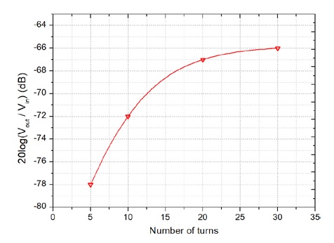
Figure 11 shows the ratio of the output to input voltage according to the number of turns when a metal wall is inserted between the transmitting and receiving coils. Because the inner and outer diameters of the toroidal coil are determined by the simulation model, the results are presented by changing only the number of turns. At 20 or more turns, the coupling efficiency between the two coils is saturated.
3. Experiment and Results
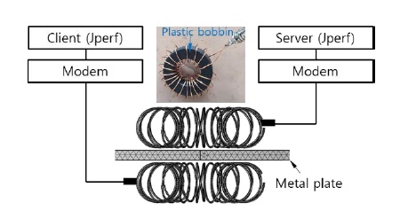
Figure 12 shows the block diagram of the MI communication testing system using a toroidal helix coil. The coil was manufactured by winding an enamel wire around a bobbin. Because the material of the bobbin was plastic, it only served to maintain the shape of the coil. Each coil is connected to a modem and PC to measure the communication bandwidth.
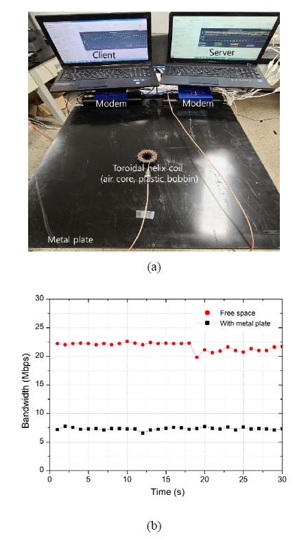
The setup for the MI communication experiment is shown in Figure 13(a). The two coils are fixed to the top and bottom of the metal plate, respectively. The PC was running Jperf, which is a test tool used to measure the throughput of a network that generates and transmits TCP and UDP data streams. After setting one of the PCs as a server and the other as a client, the communication bandwidth is measured for a certain period of time. The experimental results are shown in Figure 13(b). The communication bandwidth was measured at 1-second intervals for 30 s. In free space without a metal plate, the average bandwidth was 22 Mbps, but with the metal plate between the two coils, the bandwidth was reduced by a third. However, Mbps-class communication connections were maintained.
4. Conclusions
We proposed a toroidal helix coil as an antenna for MI communication in an environment with metal walls. Simulation modelling and electromagnetic analysis were performed using COMSOL AC/DC module. In the EM waves generated from the coil antenna, most of the electric field is blocked by the metal plate, but the magnetic field is partially transmitted to the opposite side. Based on the analysis, a pair of coils with 20 windings were fabricated, and their MI performance was tested. As a result, an average communication bandwidth of 7 Mbps was obtained when a 5 mm thick metal plate was placed between the two coils. This is approximately 30% of the results for free space. Although the communication bandwidth varies depending on the material and structure of the metal plate, MI communication using a toroidal helix coil is an effective alternative to the conventional communication techniques in metal-enclosed wireless environments such as ships.
Acknowledgments
This research was financially supported by the Ministry of SMEs and Startups (MSS), Korea, “Regional Specialized Industry Development Program (R&D, S3085628)” supervised by Korea Institute for Advancement of Technology (KIAT).
Author Contributions
Conceptualization, K. Sohn and H. Kim; Methodology, K. Sohn and H. Kim; Software, K. Sohn; Validation, K. Sohn and H. Kim; Formal Analysis, K. Sohn; Investigation, K. Sohn and H. Kim; Resources, K. Sohn and H. Kim; Data Curation, K. Sohn; Writing—Original Draft Preparation, K. Sohn; Writing—Review & Editing, K. Sohn and H. Kim; Visualization, K. Sohn; Supervision, K. Sohn; Project Administration, K. Sohn and H. Kim; Funding Acquisition, K. Sohn and H. Kim.
References
-
J. I. Agbinya and S. Lal, “A high capacity near-field induc-tive coupled MISO communication system for Internet of Things,” Proceedings of the 6th International Conference on Broadband Communications & Biomedical Applications, pp. 112-117, 2011.
[https://doi.org/10.1109/IB2Com.2011.6217903]

-
Z. Sun and I. F. Akyildiz, “Underground wireless communication using magnetic induction,” 2009 IEEE International Conference on Communications, pp. 1-5, 2009.
[https://doi.org/10.1109/ICC.2009.5199549]

-
M. Kim, S. Chae, Y. Shim, D. Lee, M. Kim, Y. Moon, and K. Kwon, “Design and implementation of magnetic induction based wireless underground communication system supporting distance measurement,” KSII Transactions on Internet and Information Systems, vol. 13, no. 8, pp. 4227-4240, 2019.
[https://doi.org/10.3837/tiis.2019.08.023]

-
I. F. Akyildiz, P. Wang, and Z. Sun, “Realizing underwater communication through magnetic induction,” IEEE Communications Magazine, vol. 53, no. 11, pp. 42-48, 2015.
[https://doi.org/10.1109/MCOM.2015.7321970]

-
S. Chen, Y. Yang, and Y. Luo, “Comparison of spiral and helix coils in magnetic resonant coupling wireless power transfer,” IEEE 2nd Information Technology, Networking, Electronic and Automation Control Conference (ITNEC), pp. 721-724, 2017.
[https://doi.org/10.1109/ITNEC.2017.8284826]

-
Z. Sun and I. F. Akyildiz, “Magnetic induction communications for wireless underground sensor networks,” IEEE Transactions on Antennas and Propagation, vol. 58, no. 7, pp. 2426-2435, 2010.
[https://doi.org/10.1109/TAP.2010.2048858]

-
M. Hott, P. A. Hoeher, and S. F. Reinecke, “Magnetic com-munication using high-sensitivity magnetic field detectors,” Sensors, vol. 19, no. 15, pp. 1-14, 2019.
[https://doi.org/10.3390/s19153415]

- EMI absorber development trend and market research Ⅱ, http://smtfocus.co.kr/article/print.asp?idx=356, , Accessed June 11, 2012.
-
C. Li, R. Liu, S. Dai, N. Zhang, and X. Wang, “Vectorbased Eddy-Current testing method,” Applied Sciences, vol. 8, no. 11, p. 2289, 2018.
[https://doi.org/10.3390/app8112289]


