Development of a unified formula for evaluating the safe working loads of ship block support structures
Copyright ⓒ The Korean Society of Marine Engineering
This is an Open Access article distributed under the terms of the Creative Commons Attribution Non-Commercial License (http://creativecommons.org/licenses/by-nc/3.0), which permits unrestricted non-commercial use, distribution, and reproduction in any medium, provided the original work is properly cited.
Abstract
To build a vessel, structural divisions (blocks) of various sizes are first used to form small and medium assemblies, and then a large assembly is formed. The building blocks are finally assembled in a dock via pre-erection to complete hulls, during which supports of various shapes are utilized to prevent overturning and control load distribution. These supports are tailored for specific sites; hence, modifying them for use in jigs may result in jig safety misestimation. Several recent cases of structural damage due to block overturning were caused by the load exceeding the allowable load of the aged supports. In this study, to develop a method for accurately predicting the safe working loads (SWLs) of supports, which are essential in shipbuilding, we performed a finite element series analysis while varying the parameters of different supports, to determine the effect of the parameters on the SWL. In addition, we compared the obtained results with the existing criteria. The Euler equation overestimated the effect of the length change and thus provided unreliable results for long supports. However, the proposed empirical formula based on nonlinear analysis accurately predicted the SWL of supports and reflected the influence of the parameters; therefore, the formula is beneficial for support design.
Keywords:
Supporting structures, Safe working load, Block overturning, Allowable load, Empirical formula1. Introduction
Structural divisions of various sizes are known as blocks in the construction of ships and offshore structures. Ship structures subjected to wind loads are susceptible to overturning, and deflection can occur between blocks of high-curvature bows and sterns during the erection process. Accidents involving overturned bow and stern blocks, which inflict injuries on nearby workers and damage surrounding structures, have recently been reported.
Most of these reported overturning accidents were caused by block movements. Insufficiently conservative safe loads of the support structures in the curved blocks resulted in the collapse of the support, thereby triggering block movements. In practical shipyard construction processes, various supporting structures are used; however, in most cases, there are no applicable regulations and international standards for their usage
In this study, to calculate the safe loads of various supporting structures in the block construction process, standardized evaluation criteria were developed via nonlinear numerical analysis, considering parameters, such as the diameter, length, thickness, and support configuration method.
Related studies are summarized as follows. The Korea Occupational Safety and Health Agency [1] conducted a structural strength test to establish a standard for a 6 m pipe support employed in construction sites. The obtained results indicated that pipe thickness, material, and diameter are important parameters for establishing a standard.
Theoretical and numerical studies have been conducted on land-based structural applications to mitigate floor post-related collapse accidents [2]. The results of the experiments with/without horizontal connectors of the floor post demonstrated that the buckling load increased by 2.2 times in the presence of the floor post. Moreover, floor posts are advantageous for field applications. The buckling load decreased by 26% and 35% when the floor post installation slope was at 5° and 10°, respectively.
Several numerical studies have been conducted on the buckling loads of thin-walled members, which are widely used in supporting structures in land-based construction. Huang and Wang [3] investigated linear elastic, geometrically nonlinear elastic, and nonlinear inelastic behaviors via mathematical formulation, experimentation, and numerical solutions. The numerical solution results indicated that the following factors influence the inelastic buckling load: constraint modeling, loading pattern, rib addition, scale factor of the initial defect, and yield strength of the material.
Using ANSYS, Ozolins and Kalnins [4] performed numerical analysis and compression experiments on thin cylindrical steel pipes. They inferred that the main buckling mode occurred at the top of the compressive load support.
Oh and Choi [5] performed a compressive strength test on a pipe support of length 4 m. Approximately 30% of the experimental models did not satisfy safety certification standards. Moreover, for models that passed the safety certification, errors were identified in quality control during the manufacturing process. According to the experimental results, the main failure modes were inner-pipe buckling, support-pin bending, female thread slipping or flaring, and female thread failure. These factors primarily determine the safe load of the pipe support. Accordingly, the authors recommended that the decrease in strength due to product reuse is a vital consideration when modifying quality control test standards or determining appropriate standards; hence, additional research is required.
Building on the literature reviewed above, this study analyzed the safe working load (SWL) as a function of several variables by comparing a simple theoretical formula and the evaluation results of the American Institute of Steel Construction (AISC) [6] against numerical analysis results. Based on these results, an evaluation formula was proposed to reflect the model characteristics. The obtained results can serve as basic data for structural safety evaluations, shipbuilding, and offshore research.
2. Characteristics of Block Support Structures
2.1 Types of block support structures
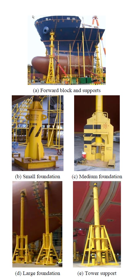
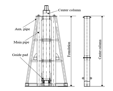
Figure 1 illustrates the various types of target support structures for ship blocks. In general, the support structures used in shipyards play an important role in preventing block overturning and dock deformation. Recently, the predominant design trend has tended toward lightweight ship structures. This includes a method widely used for quality control management between blocks in the shipbuilding industry. Conventionally, the length of a support is approximately 2.0–20.0 m. Slender structures, such as pipes, can withstand higher compressive loads when they are designed to be stronger and heavier (Figures 1(c), (d), (e)). A typical tower support is presented in Figure 2. The support is broadly divided into two parts: foundation and central pillar. The support capacity can be increased by attaching a hydraulic ram to the space below the guide pad.
2.2 Current structural design approach
In the current industrial design approach, an elastic buckling load is used to obtain the compressive force in the centroid according to the buckling differential equation
The buckling phenomenon triggered by the minimum load on the column receiving the central axial load is called the elastic buckling load of the column (Pcr), and the corresponding outcomes depend on the effective buckling coefficient. The buckling load can be calculated from the effective buckling coefficient (n) using Equation (1).
| (1) |
where denote the elastic buckling strength, elastic buckling load of the column, secondary moment of the section, minimum secondary radius of the section, slenderness ratio, and effective buckling coefficient, respectively.
The elastic buckling equation (Equation (1)) provides the elastic buckling stress. Modifying the equation to correct for plasticity [7] results in Equation (2)
| (2) |
where σY represents the material yield strength.
Timoshenko proposed Equation (3) to calculate the elastic buckling stress of a cylinder subjected to a uniform compressive load [8]. Similarly, the plasticity correction expressed by Equation (2) can be adopted as:
| (3) |
where σcr, E, t, R, and, v denote the buckling stress, elastic modulus, thickness, radius, and Poisson’s ratio, respectively.
Therefore, the current approach to calculating the safe loads of various types of supports based on the classical theoretical formula (Figure 2) neglects the member parameters (diameter, length, thickness, and varying supporting foundation). Adopting this theoretical formula can result in high overestimations of the design load.
3. Development of a Unified Formula
3.1 Numerical analysis of support structures
In this study, a commercial finite element code based on MSC Nastran code [9] was utilized. A two-dimensional shell element with four nodes was adopted for the modeling. To accurately model the buckling behavior under compressive loading, the mesh size of the element was set to 40 mm. Specifically, 17,142 finite element nodes and 7,242 elements were used, and the element size was 5–30 mm, to realize sufficient degree-of-freedom for the overall deflection shape and stress.
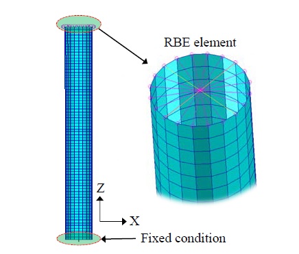
A fixed support (i.e., with x, y, and z fixed) boundary condition was applied to the area in contact with the ground (Figure 3). Here, 1 T of load was applied in the linear buckling analysis, and in the nonlinear buckling analysis, the final strength of the support was checked for a sufficiently large increment. For example, a tower support of diameter 500 mm and length 17 m required 200 T, and the SWL was 63 T.
In the linear buckling analysis, the Nastran 105 solver [10], which can calculate large deformations, was adopted to analyze the geometric nonlinearity. For the nonlinear final strength analysis, the material nonlinearity was considered using an elastically perfect plastic model for simulation of the elastic-plastic buckling strength behavior.
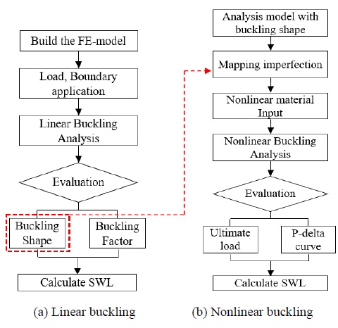
Linear and nonlinear buckling analyses were performed in this study. The procedures for both analyses are presented in Figure 4.
Linear buckling analysis can predict the critical buckling load by quantifying the buckling response of a structure to the load. The key features of linear buckling analysis are the buckling eigenmode shape (buckling model shape) and stress distribution. In the nonlinear buckling analysis, the eigenmode shape was utilized to model the initial geometrical imperfections. To consider the effect of the initial deflection that occurs during the manufacture or operation of an actual structure, an amplitude of 0.001% of the maximum initial deflection of the support length was applied to the mode with the highest buckling probability.
The buckling, yielding, and ultimate strengths were calculated via a nonlinear iterative approach according to the load increment method, and the maximum displacement value for the load was stored for each incremental process.
The SWL can be determined from the results, and the safety factor was set to 2.0 [11]. This factor was set according to the effect of residual stress, initial deflection, and eccentricity of the support. The elastic limit lies between the ultimate strength of the support and SWL divided by a safety factor of 2.0. This evaluation approach yielded a sufficiently safe design.
3.2 Numerical results
The nonlinear series analysis was performed according to the design variables (length, diameter, thickness, with/without foundation), and the obtained results were analyzed in terms of structural behavior.
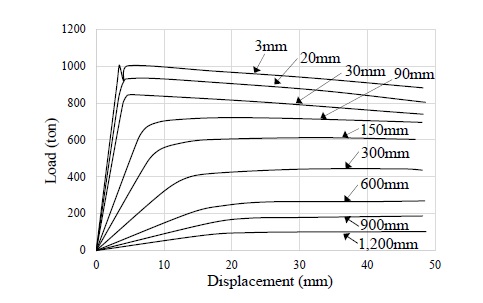
Figure 5 presents the load–displacement relationship for a general pipe support with lengths of 3.0 m and 6.0 m under normal design conditions (length, diameter, thickness, and effect of foundation). A pipe diameter of 610 mm was selected, which is more commonly used than the 500 mm variant in offshore topside modules to support large compressive loads. The ultimate strength of the support does not decrease considerably with increasing length, as the strengths at support lengths of 3.0 m and 6.0 m are 1000 T and 970 T, respectively; however, the structural stiffness gradient decreases significantly with increasing length.
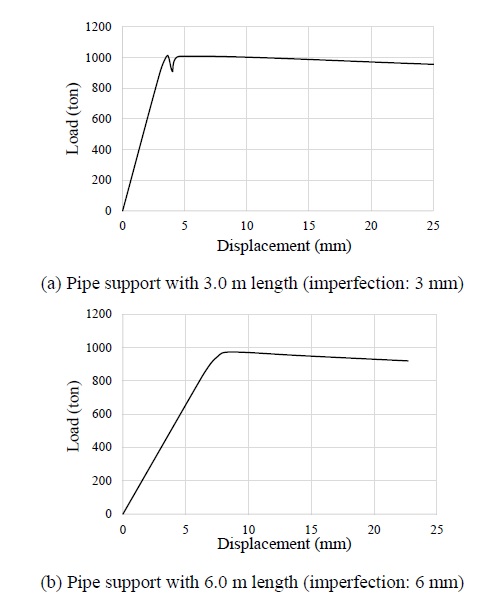
Progressive collapse behavior of a typical pipe support under axial compressive loading for varying support lengths
Table 1 compares the results obtained from the theoretical equations, linear buckling analysis, and nonlinear buckling analysis of supports under normal sea conditions. At a 3 m support length, the buckling strength values predicted by the two theoretical equations are similar, whereas the linear buckling analysis result is 5% higher than the results obtained from the theoretical equations. The nonlinear buckling analysis considers the initial deflection; therefore, the calculated strength value is 1% less than that obtained via the linear buckling analysis. At a 6 m support length, the Euler equation and linear buckling analysis predicted similar load values, and the load value prediction exhibited the same tendency as the ultimate strength prediction.

Buckling load results of theoretical equations and numerical calculation for 3.0 and 6.0 m support length
These results verified that the theoretical value changes with the support length.
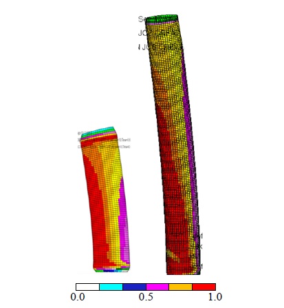
Figure 6 presents the yield stress distribution at the ultimate strength for both support lengths. Both supports exhibited similar stress patterns in different regions.
Figure 7 illustrates the effect of buckling and ultimate strengths of the support according to the initial deflection induced by the welding and manufacturing processes. With increasing initial deflection, the slope of the in-plane stiffness of the support decreases considerably, thereby resulting in buckling and ultimate strength underestimation. This result indicated that the emergence of deformation during the manufacturing and handling stages of the support may be the main cause of SWL reduction.
Various supports are used in shipbuilding yards (refer to Figure 1), and they can be broadly classified into supports with foundation and supports without foundation.
Generally, the foundation is more rigid than the post support; hence, it plays an important role in determining the effective buckling length of the support under compressive loading (Figure 8). As illustrated in Figure 8(b), the foundation serves as a buckling support point, and the foundation effect can reduce the buckling length of the upper support.
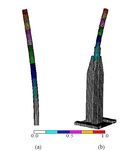
Comparison of deformed shapes having supports (a) with and (b) without foundation under axial compressive loading
Figure 9 compares the effect of the support length on the SWL in the presence and absence of a foundation. The pipe length exerted a more significant effect on the SWLs of shorter pipes. The effect was attenuated at lengths ≥ 11 m.
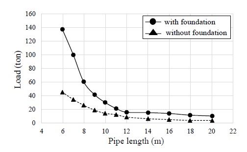
Comparison of SWLs in cases with and without foundation under axial compressive loading (diameter: 273 mm, thickness: 12.7 mm)
For example, vessels with high-curvature hull skin structures, such as large container ships, often feature supporting post lengths > 10.0 m. Therefore, conditions for maximizing the foundation effect according to the support diameter, thickness, and length should be carefully developed. The effective buckling length is reduced proportionally to the length reduction triggered by the foundation attachment; hence, the effect of the increase in load is not directly reflected in Equation (3).
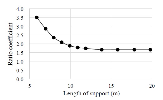
In this study, the support length corresponding to the SWL in the presence of the foundation effect was set to 9.0 m, according to the turning point in the graph of the SWL ratio coefficient versus length (Figure 10). Unified evaluation criteria can be developed with two regions according to a support length of 9.0 m.
3.3 Unified design formula
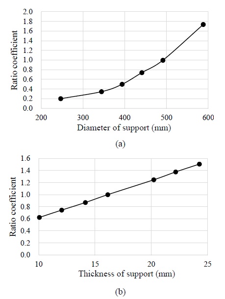
To develop a unified formula, the SWL was expressed in terms of the relationship between the support diameter and thickness obtained from the series analysis results (Figure 11). The effect of the support diameter and thickness can be expressed as a two-dimensional parabolic equation and a one-dimensional linear equation, respectively.
Equations (4) and (5) were empirically derived to calculate the SWL for each support length. The equations independently define the correlations between relevant variables.
| (4) |
| (4a) |
| (4b) |
| (4c) |
| (5) |
| (5a) |
| (5b) |
| (5c) |
where L, SFD, SFt, MEF, and OD represent the support length, coefficient related to the change in the support diameter, coefficient related to the change in the support thickness, coefficient related to the influence of the foundation model, and outer diameter of the support, respectively.
Equations (4) and (5) were used to predict the SWLs for shorter and longer supports (<9.0 and >9.0 m, respectively). The equations considered the support diameter, thickness, and foundation effect.
The influence of the support length cannot be directly calculated using the Timoshenko equation (Equation (3)). However, with a short support corresponding to a diameter and thickness of 250 mm and 16 mm, respectively, the SWL calculated by the Timoshenko equation is similar to that calculated by the Euler equations (Equations (1) and (2)). Nevertheless, slight differences do emerge because the proposed formulas were developed according to the results of the nonlinear final strength analysis with material and geometrical nonlinearity. In particular, the SWL values were overestimated in the case of the short-pipe support (Figure 12).
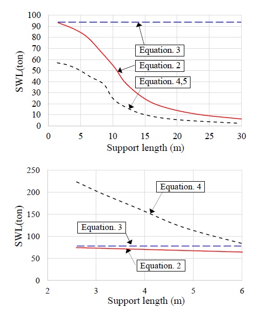
Comparison of SWLs obtained from the theoretical equation and numerical analysis for pipe support (top) and tower support (bottom) (D = 250 mm, thickness = 16 mm)
Figure 13 compares the results obtained from the theoretical equation and proposed formulas for a support with a foundation. The SWL values for a support with a diameter and thickness of 250 mm and 12.7 mm, respectively, exhibited a comparable pattern to the theoretical formula results, while the proposed formula yielded higher SWL values because it considered the foundation effect. Therefore, during the design of the foundation support, the proposed formula should be adopted to account for the foundation effect.
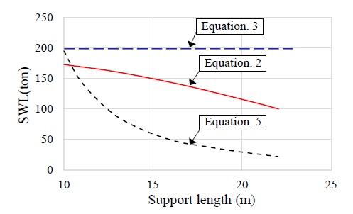
Comparison of SWLs obtained from the theoretical equation and the numerical analysis of the tower support (D = 500 mm, thickness = 16 mm)
The SWL values predicted by the theoretical and proposed formulas exhibited different tendencies for supports with diameter and thickness of 500 mm and 16 mm, respectively. As mentioned above, the SWL obtained using the proposed formula gradually changed with increasing support lengths > 9 m. The proposed formulas were based on realistic characteristics of the relevant material and geometrical nonlinearity; hence, they accurately reflected the effect of changes in length.
4. Conclusion and Remarks
This study presents the results of a nonlinear series analysis to predict the SWLs of general posts, simple towers, and tower supports, which are widely used in the manufacturing of blocks for ships and offshore projects. SWL evaluation criteria that can be conveniently adopted in the industry were presented, and their applicability was verified. By comparing with existing theoretical formulas used in current industrial practices, the limitations of the proposed criteria under extended application were also analyzed, and the corresponding improvements were integrated into the proposed formula.
This study provides a convenient method for systematic SWL estimation, application, and analysis; hence, it will be beneficial to engineers in related industries. The following conclusions were drawn from this study:
- • To obtain valid SWL values, the effect of the reduction in effective buckling length due to foundation attachment should be considered in the modeling of various supports.
- • The support thickness variable is characterized by a linear behavior; however, the diameter is characterized by a two-dimensional parabolic distribution according to the influence of the thickness.
- • The shorter the support, the more significant the foundation effect; the foundation effect is minimal at support lengths ≥ 9.0 m.
- • The initial deflection induced in the manufacturing and operation stages significantly affects SWL and is an important factor in maintenance and repair.
- • The existing theoretical formula underestimates the effect of the support length on SWL, which can result in an overestimation of the safe load.
- • The proposed formula is applicable to the design and management of supports used both in shipyards and related industrial sites.
Future studies should develop an evaluation formula that can be extended and applied to small (small diameter and short length) supports that are not covered in this study.
Author Contributions
Conceptualisation, J. S. Park; Methodology, J. S. Park and J. K. Seo; Validation and Preparation of Original Draft, J. S. Park; Review and Editing, J. K. Seo; Visualisation and Supervision, J. K. Seo; Project Administration, J. S. Park.
References
- Korea Occupational Safety and Health Agency (KOSHA). “A Study on the Standards of Function Inspection for 6m Pipe Support,” KOSHA Research Report (S-RD-I-2002-01-07), pp. 5-19, 2002.
- D. W. Kang and Y. B. Kwon, “A study on the structural behaviour and the strength of circular hollow steel (CHS) section columns,” Journal of Korean Society of Steel Construction, vol. 21, no. 5, pp. 505-514, 2009 (in Korean).
-
J. S. Lee, Y. S. Lee, and T. K. Oh, “Effect of horizontal connection and slope on buckling characteristics of single pipe,” Journal of the Korean Society of Safety, vol. 30, no. 2, pp. 48-55, 2015 (in Korean).
[https://doi.org/10.14346/JKOSOS.2015.30.2.48]

-
L. Huang, B. Li, and Y. Wang. “Computation analysis of buckling loads of thin-walled members with open sections,” Mathematical Problems in Engineering, vol. 2016, pp. 1-9, 2016.
[https://doi.org/10.1155/2016/8320469]

-
O. Ozolins and K. Kalnins, “An experimental buckling study of column-supported cylinder, Procedia Engineering,” vol. 172, pp. 823-830, 2017.
[https://doi.org/10.1016/j.proeng.2017.02.130]

- B. H. Oh and B. J. Choi. “A study on improvement of safety & quality management standard based on compression tests of steel pipe supports,” Journal of the Korean Society of Safety, vol. 33, no. 2, pp. 94-103, 2018 (in Korean).
- S. P. Timoshenko and J. M. Gere, Theory of Elastic Stability, 2nd edition, McGraw-Hill, London, United Kingdom, 1982.
- J. K. Paik and A. K. Thayamballi, Ultimate Limit State Design of Steel-Plated Structures, John Wiley & Sons, Ltd, United Kingdom, 2003.
- AISC, Specification for Structural Steel Buildings, American Institute of Steel Construction, Chicago, Illinois, 2016.
- MSC Software, Patran 2012 User’s Guide: Material modeling (Chapter 6), MSC Software, pp. 125-136, 2012.
- API, Recommended Practice for Planning, Designing and Constructing Fixed Offshore Platforms-Working Stress Design, American Petroleum Institute, Washington, D.C., 2007.

