[ISMT2021] Numerical analysis of thermal and flow friction in lid-driven grooved enclosure using Lattice Boltzmann Method
Copyright ⓒ The Korean Society of Marine Engineering
This is an Open Access article distributed under the terms of the Creative Commons Attribution Non-Commercial License (http://creativecommons.org/licenses/by-nc/3.0), which permits unrestricted non-commercial use, distribution, and reproduction in any medium, provided the original work is properly cited.
Abstract
A numerical simulation is performed to investigate the heat transfer and fluid flow behaviors in a lid-driven triangular grooved enclosure using an alternative traditional method known as the Lattice Boltzmann Method (LBM). Geometrical parameters, such as the aspect ratios of the groove, and other non-dimensional parameters are considered in the present study. The results are presented as a stream function in terms of velocity, average rate of heat transfer in terms of the Nusselt number (Nu), and flow friction on the moving lid for a wide range of Reynolds numbers (Re), as well as a mixed convection parameter known as the Richardson number (Ri). The flow and temperature profiles inside the cavity are affected more by the non-dimensional parameters than the grooved depth ratios. It is noted that the fluid friction on the moving lid decreases as Re and Ri increases; consequently, the heat transfer rate increases significantly. To validate the present model, the LBM results are compared with the conventional benchmark results, where excellent agreement is indicated.
Keywords:
Heat transfer, Flow friction, Grooved enclosure, Reynolds number, Lid driven, Lattice Boltzmann1. Introduction
Mixed convection or combined free and force convection has garnered significant attention over the past several decades owing to its practical applications in the electronic cooling industry. Mixed convection in grooved channels or cavities using various methods has been investigated extensively [1]-[3]. Mustafa et al. [4] reviewed the heat transfer process based on the mixed convection of a lid-driven cavity with various geometries. They discussed heat transfer enhancement techniques based on different velocity and thermal boundary conditions for several cavity geometries, such as triangles, squares, circles, rectangles, and waves with lids. In fact, a lid-driven cavity is crucial for analyzing heat transfer and fluid flow characteristics. Fluid flow is initiated by a moving wall, whereas heat transfer occurs owing to the temperature gradient between hot and cold walls. Saha et al. [5] conducted a numerical study pertaining to transverse mixed convection inside a vented enclosure with different inlet and outlet locations. They showed that the temperature distribution in flow fields depended significantly on the inlet and outlet positions. Using the finite element method, Roy et al. [6] reported problems associated with natural convection heat transfer and fluid flow in a triangular enclosure with uniform and non-uniform bottom heating. The effects of various types of cavity shapes on thermal and fluid behaviors in lid-driven cavity flows have been investigated using different methods [7][8]. In this regard, Chen et al. [8] used a finite element formulation based on the Galerkin method to solve the associated problems.
In recent years, the Lattice Boltzmann Method (LBM), which is based on the Boltzmann equation, has been used extensively as an alternative to the traditional approach for solving the Navier–Stokes (N–S) equations numerically [9][10]. In conventional Computational Fluid Dynamics (CFD) simulations, the macroscopic N–S approach is used to simulate fluid flows, whereas in the LBM, a mesoscopic simulation model is used instead of directly solving the macroscopic fluid quantities (velocity, pressure, and temperature), and the movement of the fluid particles is considered with a few approximations. The problem of mixed convection, which combines both free and force convection, and flow based on the thermal Lattice Boltzmann Method (TLBM) has been investigated extensively [11]-[13]. Some authors considered different types of lid-driven enclosures with and without heat generation as well as various boundary conditions [14]-[16].
The main purpose of this study is to numerically investigate the geometry effect, in particular the effect of the groove depth of a lid-driven cavity on the flow and convective heat transfer, using the TLBM with other governing parameters, namely the Richardson number (Ri) and Reynolds number (Re). The application of this study was observed in an electronic chipset, where free convection is insufficient for providing effective cooling. A few investigations pertaining to solving this type of problem using the TLBM have been reported. To the best of our knowledge, the method proposed herein has not yet been considered. The computations for the present simulation were performed using a code developed by the authors that is written in the FORTRAN language.
2. Theoretical Analysis
2.1 Problem statement
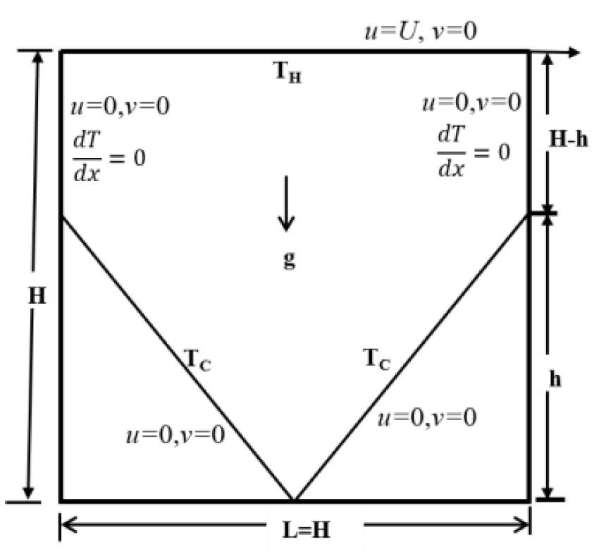
The geometry and boundary conditions of the present problem are shown in Figure 1. The aforementioned problem is a two-dimensional lid-driven square-grooved cavity with a side length of H. The grooved depth ratio (GDR) is defined as h/H, where h is the groove depth. If the GDR = 0, the cavity is a square, and if the GDR = 1.0, the cavity is a triangle. For 0 < GDR < 1, a pentagon-shaped cavity is represented. Therefore, the shape of the cavity depends on the GDR. In the present study, GDR = 0.0, 0.25, 0.50, and 1.0, where the lid of the cavity was maintained at a uniform higher temperature TH and a steady velocity U. When GDR = 0.0, the lower wall was maintained at a lower temperature TC, whereas the left and right walls were assumed to be adiabatic. When 0 < GDR < 1, a pentagon is represented, whose two sliding inclined walls are at a lower temperature TC, whereas the left and right vertical walls (H - h) are adiabatic. However, if GDR = 1.0, the cavity becomes a triangle; in this case, the two inclined walls maintain a lower temperature TC, whereas the upper wall is moving at a higher temperature. It is noteworthy that in this case only, no wall exists or the wall portion is adiabatic. The working fluid is considered as incompressible and Newtonian. with air properties such as a Prandtl number of 0.713.
2.2 Mathematical Formulation of Problem
To express the Lattice Boltzmann equations for flow and temperature fields with external forces in the general form, it is important to consider the Bhatnagar, Gross, and Krook approximation, where the relaxation parameter for momentum (τm) is associated with the viscosity (ν) of the fluid. It is based on the notation of a local equilibrium that corresponds to a Maxwell–Boltzmann distribution evaluated at each point in space for the local values of density, velocity, and temperature.
| (1) |
| (2) |
Here, fk and gkare the particle and energy distribution functions for a finite set of discrete particle velocity vector ek, respectively, where k = 0, 1, …, 8; Δt denotes the Lattice time step; F is the external force in the direction of the Lattice velocity; τm and τT represent the Lattice relaxation times for the flow andtemperature fields, respectively. The LBM is established based on the D2Q9 model (two-dimensional Lattice with nine particle velocities), i.e., each node of the Lattice contains three types of particles: a rest particle, particles that traverse in the coordinate directions, and particles that traverse in the diagonal directions. Therefore, the equilibrium distribution functions for momentum and energy can be formulated as follows, respectively:
| (3) |
| (4) |
where u and ρ are the macroscopic velocity and density, respectively; wk is the weighting factor; is the Lattice speedof sound; c=Δx/Δt is the Courant–Friedrichs–Lewy number; Δx and Δt are the Lattice space and Lattice time steps, respectively. The internal energy variable of the fluid particles is represented by ε=Σkgk(x, t). The kinetic viscosity υ and thermaldiffusivity α are defined in terms of their respective relaxation times as and .
To introduce the force term to the model, the buoyancy force can be calculated in the vertical direction as F=3ωkgyΔT . To ensure that the problem is applicable to a near-incompressible regime, the characteristic velocity for both the natural and force regimes should be small compared with the fluid speed of sound. Uw is the upper moving lidvelocity, H is the height of the cavity, and Re is the Reynolds number. The ratio of the buoyancy force to the product of the viscous force and heat diffusion rates defines the Rayleigh number (Ra) as , where denotes the Grashof number, and PR=υ/α is the Prandtl number. Therefore, the mixed convection parameter, known as the Richardson number, can be expressed as .
In convection, flow is driven by the temperature or mass gradient, i.e., by the buoyancy force, where the momentum and energy equations are coupled. Hence, an additional force term must be considered when solving the LB equations. The macroscopic variables of interest, such as density, velocity, temperature, and pressure, can be obtained easily from microscopic particle distribution functions for momentum and energy by solving Equations (2)-(4) using other LBM approaches.
| (6) |
The solutions of the velocity and temperature fields are used to evaluate the heat transfer performance and the shear stress on the moving lid, respectively. The local heat transfer performance on the moving lid can be evaluated using the local Nusselt number Nux, which is expressed as
| (7) |
where hx is the local heat-transfer coefficient. Therefore, based on the result of Nux, the average Nusselt number on the moving lid can be evaluated by integration as follows:
| (8) |
Meanwhile, the local friction factor on the moving lid can be expressed in terms of the local shear stress as
| (9) |
Based on the local friction, the average friction on the moving lid surface can be calculated by integration as follows:
| (10) |
2.3 Code Verification
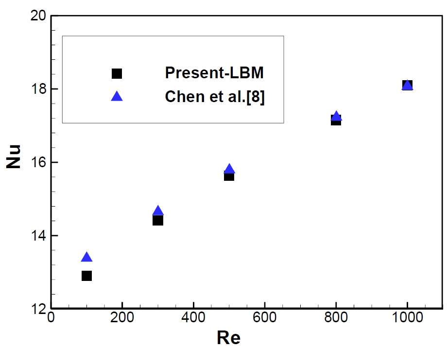
To verify the code of this model, the results obtained were compared with the results of Chen et al. [8]. It is noteworthy that Chen et al. [8] used a different numerical approach, i.e., the finite volume method, instead of the LBM, for solving the governing equations. The variation in Nu with Re shown in Figure 2 was based on the moving lid of a triangular enclosure filled with air, where Pr = 0.71. The results of the present LBM simulations agreed well with the numerical results of Chen et al. [8]. Hence, the accuracy of the proposed simulation model was confirmed.
3. Results and Discussions
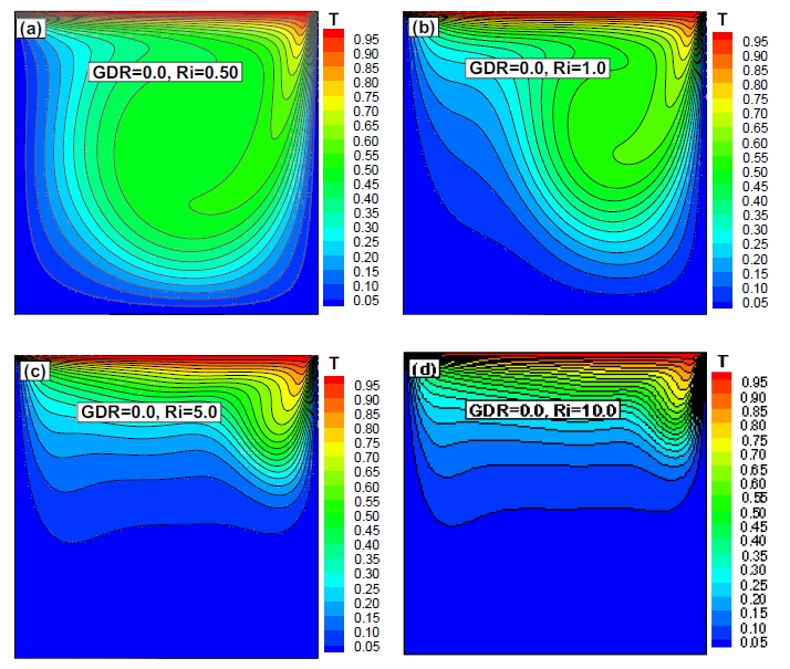
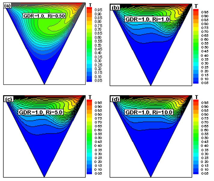
The numerical results of fluid flow and temperature profiles inside the grooved cavity for various cases are shown using isotherms and streamlines, respectively. Figures 3-6 show the effect of the mixed convection parameter for various (GDRs) on the temperature profile in terms of isotherms.
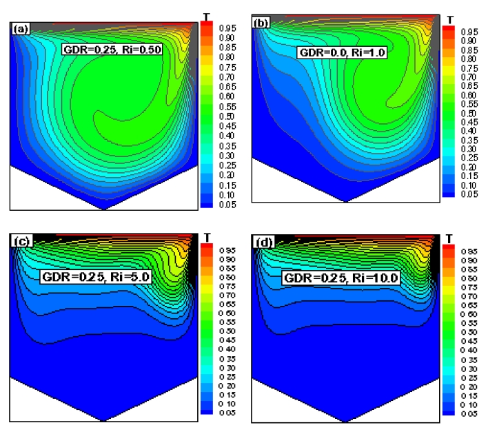
Isotherms for Re = 200, GDR = 0.25 with (a) Ri = 0.50, (b) Ri = 1.0, (c) Ri = 5.0, and (d) Ri = 10.0
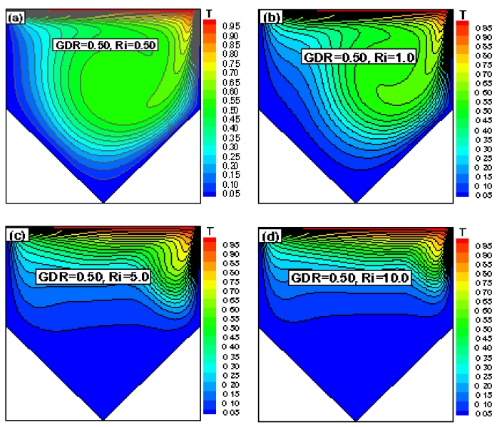
Isotherms for Re = 200, GDR = 0.50 with (a) Ri = 0.50, (b) Ri = 1.0, (c) Ri = 5.0, and (d) Ri = 10.0
As shown in the figures above, when Ri = 0.50 and 1.0, i.e., when forced convection was dominant compared with natural convection, the isotherms showed the greatest effect. It was evident that the effect of the buoyancy force decreased. Increasing the retarding force, i.e., the buoyancy force, prevents the return flow from penetrating the bottom of the cavity. As Ri increased, the natural convection strengthened, whereas forced convection weakened; therefore, the change in the isotherms was insignificant. This is because the two vertical walls (left and right) were adiabatic, and no heat exchange occurred between the fluid and walls, although the inclined walls were maintained at a cold temperature. However, if the values of the GDR increase from 0.0 to 1.0, then the isotherms will be slightly affected.
The velocity profiles in terms of streamlines for different values of Ri and GDR with Re = 200 are shown in Figures 7–10. As shown in Figure 7, when GDR = 0.0, a square cavity was represented. A strong primary vortex or circulation was observed throughout the cavity owing to the dominance of force convection when Ri = 0.50.
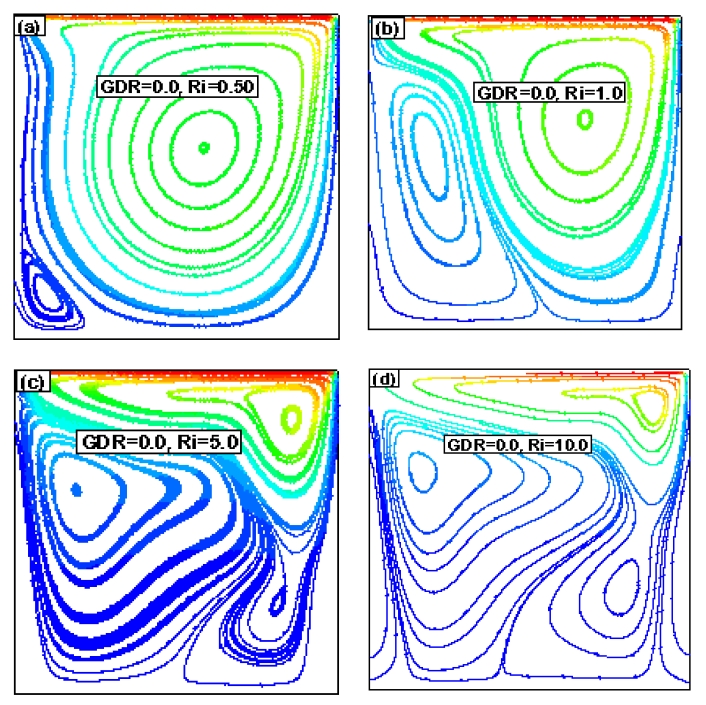
Streamlines for Re = 200, GDR = 0.0 with (a) Ri = 0.50, (b) Ri = 1.0, (c) Ri = 5.0, and (d) Ri = 10.0
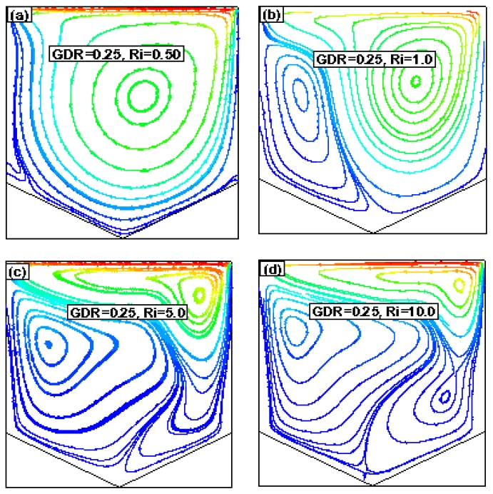
Streamlines for Re = 200, GDR = 0.25 with (a) Ri = 0.50, (b) Ri = 1.0, (c) Ri = 5.0, and (d) Ri = 10.0
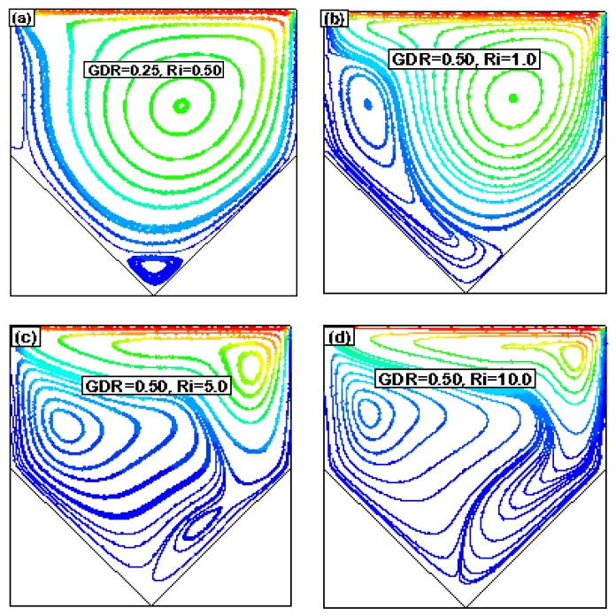
Streamlines for Re = 200, GDR = 0.50 with (a) Ri = 0.50, (b) Ri = 1.0, (c) Ri = 5.0, and (d) Ri = 10.0
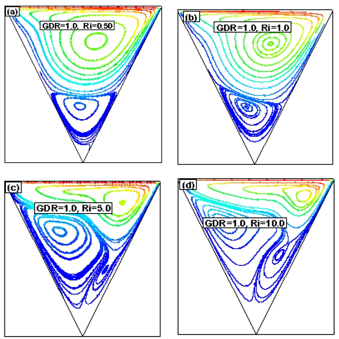
Streamlines for Re = 200, GDR = 1.0 with (a) Ri = 0.50, (b) Ri = 1.0, (c) Ri = 5.0, and (d) Ri = 10.0
In addition, a weak secondary circulation was observed at the left end of the bottom corner of the cavity. As Ri increased further, the weaker circulation strengthened, and a tertiary circulation zone was created. The same types of flow phenomena were observed as the GDR increased; however, the center of the flow circulations shifted with the Ri and GRD. Finally, when GRD = 1.0, a triangular cavity was represented.
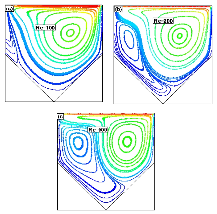
For Ri = 0.50 and 1.0, force convection was dominant; therefore, the fluid was recirculated in the upper portion of the cavity, and a strong primary vortex was formed, as shown in Figures 10(a)–(b). The upper recirculation induced shear on the lower fluid layer and formed another weak recirculated flow region, known as a secondary vortex. When Ri = 5.0 and 10.0, the secondary flow region strengthened and resulted in more tertiary flow regions in the cavity. The main vortex was associated with the movement of the hot lid, whereas the secondary vortex was associated with the buoyancy force mechanism.
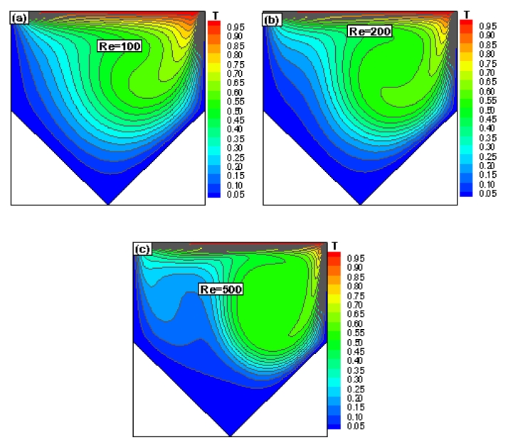
Figures 11-12 show the effect of Re on the temperature and velocity profiles for GDR = 0.50 and Ri =1.0. A strong vortex was observed inside the cavity, which is known as the main or primary vortex, where a small recirculation appeared below the primary vortex, and a side vortex appeared near the top left side of the main vortex. To increase Re, the side vortex merged with a small vortex such that the secondary vortex expanded and strengthened. As shown in Figure 12, when Re = 100, the fluid near the cold inclination walls propagated easily toward the hot surface owing to the low Re with buoyancy effects. As the secondary vortex enlarged with increasing Re, the secondary vortex prevented the fluid near the left cold wall from propagating easily to the hot region, as shown in Figure 12(c).
The average friction and heat transfer rate in terms of Nu along the hot upper surface at different GDRs for different combinations of Re and Ri are shown in Figures 13-14.
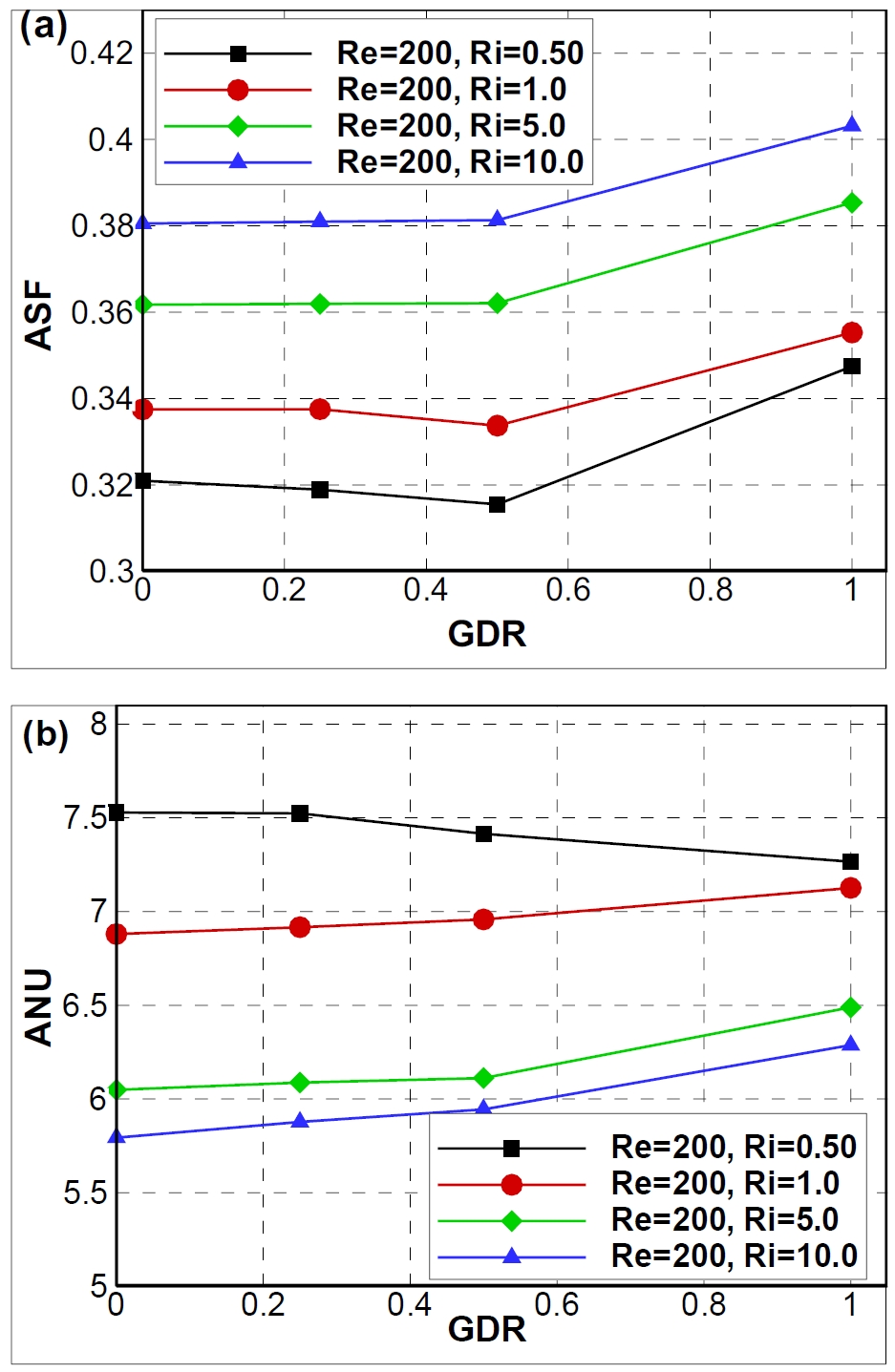
(a) Average friction and (b) average heat transfer rate vs. GDR for different values of Ri with Re = 200
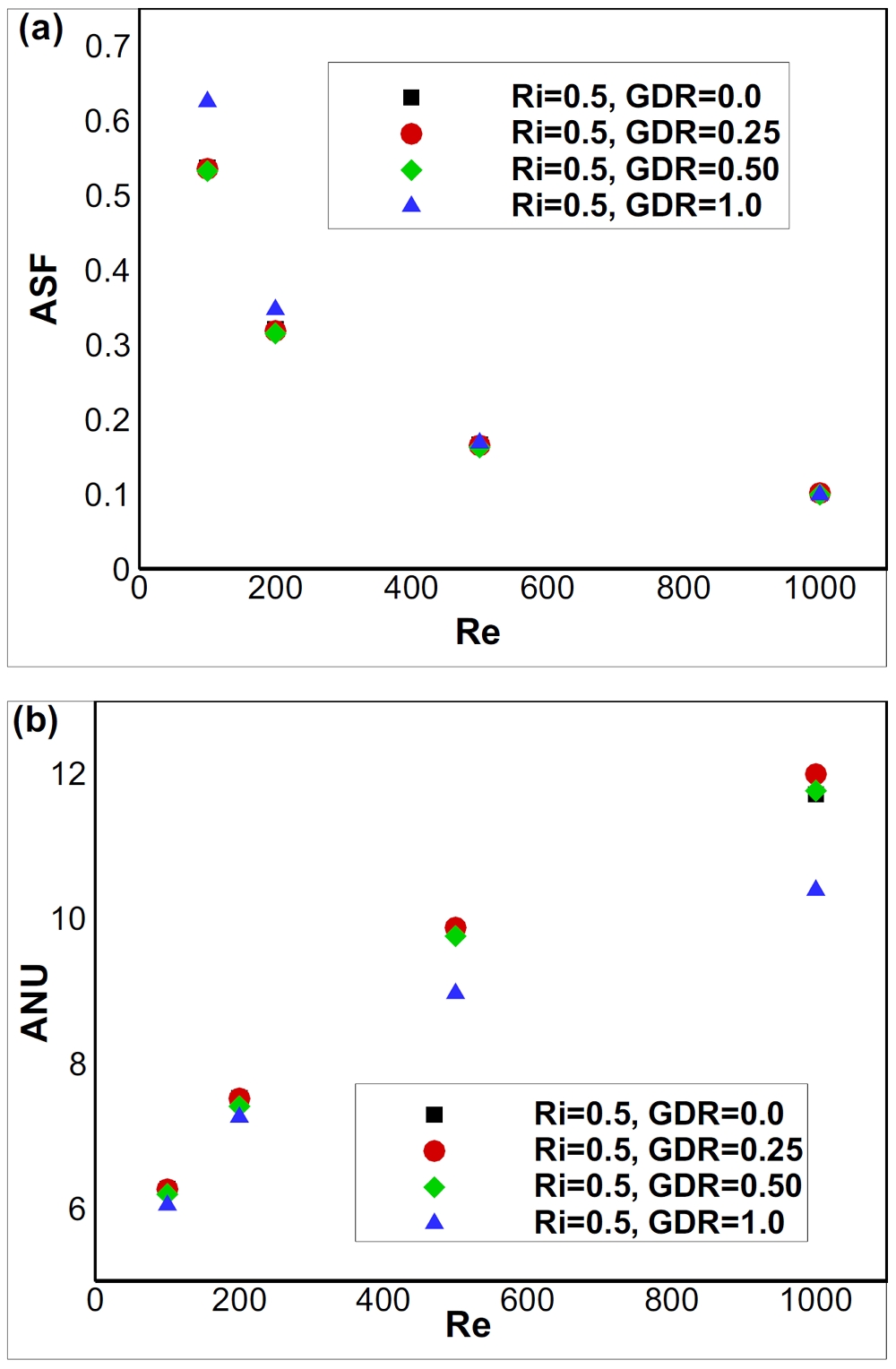
(a) Average friction and (b) average heat transfer rate vs. Reynolds number for different GDRs with Ri = 0.50
As shown in Figure 13(a), for a constant lid velocity, where Re = 200, the average friction on the moving lid was negligible for extremely small GDRs, whereas for GDR > 0.50, the friction increased linearly. Moreover, the friction increased significantly as Ri increased from 0.50 to 10.0. The heat transfer rate increased linearly with the GDR when the GDR was greater than 0.5. For Ri = 0.50, forced convection was dominant compared with free convection, and only one main recirculation region was present. Therefore, Nu was high but remained almost constant at lower GDRs. When GRD ≥ 0.50, two recirculation regions were present, as shown in Figures 9(a) and 10(a). This adversely affected heat transfer, thereby resulting in a slightly decreased average heat transfer rate, as shown in Figure 13(b) for Ri = 0.50. However, as the value of mixed convection parameter Ri increased, the heat transfer rate decreased significantly.
Figure 14 shows the effect of Re on the average flow friction and heat transfer on the moving lid for different GDRs with a fixed Ri = 0.5. As shown, friction decreased as Re increased; however, friction was negligible at higher Re values. For a lower Re with a GDR > 0.50, this effect was significant. However, the average heat transfer rate in terms of Nu increased significantly with Re and slightly decreased with the GDR for Ri = 0.50. Furthermore, when Ri = 1.0, 5.0, and 10.0, the heat transfer rate decreased linearly with the GDR.
4. Conclusion
The fluid flow and thermal properties inside a lid-driven grooved enclosure with various GDRs (GDR = 0.0–1.0) were discussed herein based on the effects of mixed convection parameters, i.e., Ri = 0.50, 1.0, 5.0, and 10.0 and Re = 100–1000. The following conclusions were obtained:
Fluid flow and temperature were affected significantly by the mixed convection parameters, namely the Ri and Re. However, they were not affected significantly by the GDRs.
A strong primary vortex was formed in the case where force convection dominated. Consequently, the isotherms were uniformly distributed throughout the cavity. However, for the free convection dominant case, some secondary and tertiary vortices were observed simultaneously with the primary vortex; consequently, the isotherms were non-uniformly distributed inside the cavity.
The average flow friction on the moving lid of the cavity decreased as Re and Ri increased. Moreover, the effect of flow friction was negligible at low GDRs, although it increased linearly when GDR > 0.50. The overall heat transfer rate in terms of Nu increased linearly with Re and the GDR. However, it decreased significantly as the value of the mixed convection parameter increased.
Acknowledgments
This paper is an expanded version of the proceeding paper entitled “Numerical Analysis of Thermal and Flow friction in a Lid-Driven Grooved Enclosure using Lattice Boltzmann Method” presented at the KOSME ISMT 2021.
Author Contributions
Conceptualization, Y. W. Lee; Methodology, Y. W. Lee and M. A. Taher; Software, M. A. Taher; Formal Analysis, M. A. Taher; Investigation, M. A. Taher, M. M. R. Liton, and R. Biswas.; Resources, Y. W. Lee; Data Curation, M. A. Taher; Writing-Original Draft Preparation, M. A. Taher; Writing-Review & Editing, M. M. R. Liton, R. Biswas, and P. Chakma; Visualization, M. A. Taher and Y. W. Lee; Supervision, M. A. Taher and Y. W. Lee; Project Administration, Y. W. Lee; Funding Acquisition, Y. W. Lee.
References
-
A. K. Sharma, P. S. Mahapatra, N. K. Manna, and K. Ghosh, “Mixed convection in a baffled grooved channel,” Sadhana-Academy Proceeding in Engineering Science, vol. 40, Part-3, pp. 835-849, 2015.
[https://doi.org/10.1007/s12046-014-0328-4]

-
X. Wan and G. E. Karniadakis, “Stochastic heat transfer enhancement in a grooved channel,” Journal of Fluid Mechanics, vol. 565, pp. 255-278, 2006.
[https://doi.org/10.1017/S0022112006001819]

- K. R. Ananda Theertha, H. K. Narahari, and N. K. S. Rajan, “Numerical investigation of heat transfer in square duct with 450 rib-grooved turbulators,” Sastech Journal, vol. 11, no. 2, pp.1-6, 2012.
- M. A. S. Mustafa, H. M. Hussain, A. A. Abtan, and L. J. Habeeb, “Review on mixed convection heat transfer in different geometries of cavity with lid driven,” Journal of Mechanical Engineering Research and Developments,” vol. 43, no. 7, pp. 12-25, 2020.
-
S. Saha, M. T. Islam, M. Ali, M. A. H. Mamun, and M. Q. Islam, “Effect of inlet and outlet locations on transverse mixed convection inside a vented enclosure,” Journal of Mechanical Engineering, vol. ME36, pp. 27-37, 2006.
[https://doi.org/10.3329/jme.v36i0.808]

-
S. Roy, T. Basak, C. Thirumalesha, and C. M. Krishna, “Finite elements simulation on natural convection flow in a triangular enclosure due to uniform and non-uniform bottom heating,” Journal of Heat Transfer, vol. 130, pp. 032501-10, 2008.
[https://doi.org/10.1115/1.2804934]

-
A. Al-Amiri, K. Khanafer, J. Bull, and I. Pop, “Effect of sinusoidal wavy bottom surface on mixed convection heat transfer in a lid-driven cavity,” International Journal of Heat and Mass Transfer, vol. 50, no. 9-10, pp. 1771-1780, 2007.
[https://doi.org/10.1016/j.ijheatmasstransfer.2006.10.008]

-
C-L. Chen and C-H. Cheng. “Numerical study of flow and thermal behavior of lid-driven flows in cavities of small aspect ratios,” International Journal for Numerical Methods in Fluids, vol. 52, no. 7, pp. 785-799, 2006.
[https://doi.org/10.1002/fld.1203]

-
H. Chen, S. Chen, and W. H. Mathaeus, “Recovery of the navier-stokes equations using a Lattice gas Boltzmann Method,” Physical Review A, vol. 45, no. 8, pp. 5339-5342, 1992.
[https://doi.org/10.1103/PhysRevA.45.R5339]

- M. A. Taher, S. C. Saha, Y. W. Lee, and H. D. Kim., “Numerical study of lid-driven square cavity with heat generation using LBM,” American Journal of Fluid Dynamics, vol. 3, no. 2, pp. 40-47, 2013.
- A. M. Fudhail, N. A. C. Sidik, M. Z. M Rody, H. M. Zahir, and M. T. Musthafah, “Numerical simulations of shear driven square and triangular cavity by using Lattice Boltzmann Method,” World Academy of Science, Engineering, and Technology, vol. 45, pp. 190-195, 2010.
- A. A. Mohammad, Applied Lattice Boltzmann Method for Transport Phenomena, Momentum, Heat and Mass Transfer, Calgary, Canada, Sure Printing, 2007.
-
M. A. Taher, S. C. Saha, and Y. W. Lee, “Effects of aspect ratios on flow friction and thermal behavior inside a close domain using Lattice Boltzmann Method,” American Journal of Applied Mathematics, vol. 3, no. 3, pp. 1-7, 2015.
[https://doi.org/10.11648/j.ajam.s.2015030101.11]

-
T. S. Cheng, “Characteristics of mixed convection heat transfer in a lid-driven cavity with various Richardson and Prandtl number,” International Journal of Thermal Science, vol. 50, no. 2, pp. 197-205, 2011.
[https://doi.org/10.1016/j.ijthermalsci.2010.09.012]

- A. A. R. Darzi, M. Farhadi, K. Sedighi, E. Fattahi, and H. Nemati, “Mixed convection simulation on inclined lid-driven cavity using Lattice Boltzmann Method,” Iranian Journal of Science and Technology Transaction B - Engineering, vol. 35, no. M1, pp. 73-83, 2011.
-
M. A. Taher, H. D. Kim, and Y. W. Lee, “LBM simulation of friction factor and heat transfer on the moving lid of a triangular enclosure,” Heat Transfer Research, vol. 48, no. 11, pp. 1025-1045, 2017.
[https://doi.org/10.1615/HeatTransRes.2016011691]


