Study on the autonomous surface ship platform of existing ships using image processing
Copyright © The Korean Society of Marine Engineering
This is an Open Access article distributed under the terms of the Creative Commons Attribution Non-Commercial License (http://creativecommons.org/licenses/by-nc/3.0), which permits unrestricted non-commercial use, distribution, and reproduction in any medium, provided the original work is properly cited.
Abstract
Recently, interest in autonomous ships has increased significantly in the maritime industry owing to its safety and efficiency. Autonomous operation at sea requires an autonomous navigation system, autonomous engine and monitoring control system, and shore control center. However, autonomous engine monitoring and control systems are difficult to apply in existing ships because this is a more complex task consisting of engine information from the system. In this study, we developed a design method to extract digital data from the displayed monitor and to verify the possibility of extracting data from actual vessels using image processing techniques to build an autonomous ship platform on a non-autonomous ship platform. The data were extracted by connecting the camera to a single-board computer to obtain images and processing by mounting on an actual vessel. In addition, the images obtained using the camera and monitoring system screen were compared with the captured images.
Keywords:
Autonomous ship, Autonomous engine monitoring, Image processing1. Introduction
The maritime autonomous surface ship (MASS) has been named in a variety of forms, including smart ships, digital ships, connected ships, remote ships, unmanned ships, and autonomous ships, and is defined by the International Maritime Organization (IMO) to create ships that are not simply autonomous [1]-[3]. The operating levels of these autonomous surface ships are divided from the manual operating level (Level 0) to the fully autonomous operating level (Level 5) [1][2]. These autonomous surface ships require remote control technology to collect and analyze data on land and are defined to enable operational optimization of the vessel and condition management [4]. Remote control requires optimized processing of on-board data collection and processing, on-shore transmission of collected data, and on-shore data sharing [4][5].
Recently designed and built ships are designed to collect and process in-ship data using a ship integrated network called the ship area network, which allows real-time monitoring of ship status and operational information and remote diagnosis and control of the ship's integrated systems. Manufacturers, including Kongsberg, are required to meet safety and reliability requirements, and open system architecture provides for engine room automation.
However, changing existing vessels operating at home and abroad to autonomous ones takes a lot of effort and has a high cost, making it difficult to convert existing vessels into autonomous ones.
Image processing technology for existing vessels can provide a method for automated vessels. Image processing can use technology to extract information from the engine monitor image digitally, with the help of computer algorithms [6]. In addition, the images can be made available in any desired format.
We conducted a study on how on-board data can be collected through image processing. The results were analyzed by extracting data through image processing using an alarm monitoring system (AMS) screen, which is the main engine cylinder status of HANBADA's training ship at Korea Maritime and Ocean University. The AMS is a very important part of safe ship operations. The main responsibility of the AMS is to inform, detect, and alert engineers of the engine’s status and critical conditions to help manage the ship safely [7].
2. Theoretical Background
Image processing requires an understanding of optical character recognition (OCR). OCR is a technology that converts letters and images in print or photographs into digital data. OCR is a character recognition method using pattern matching techniques that selects the most similar character to the standard pattern character by comparing several predefined standard patten characters and input characters. It was a way for a person to register a pattern that distinguished characters. However, this approach has significantly lower recognition rates for low-quality images or cursive writing.
In recent years, computers have created their own rules for recognizing text in images through large amounts of data learning, instead of using deep learning-based algorithms to register characters directly by humans, leading to significant and ongoing development.
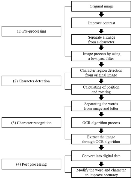
OCR based on deep learning is carried out through four stages: (1) pre-processing, (2) character detection, (3) character recognition, and (4) post-processing, as shown in Figure 1.
First, pre-processing converts the color into a gray tone and analyzes the values of the pixels to compensate for brightness and contrast. Using these calibrated images, the pixel values are divided into 0 and 1 [8].
A histogram smoothing process is performed to improve the contrast in the image to facilitate character recognition, and the image separates a smoothed image from a character through binarization with two values, 0 or 255. A low-pass filter (LPF) is applied for denoising.
Second, this pre-processed image picks out a text area during the character detection phase and rotates the text horizontally by obtaining the rotation angle of the area [9]. Character calculates the position and rotation of the character region for detection in a pretreated image and indicates the position of the letter after rotation.
The rotation angle θ according to the rotation of the character region extracted from the image can be represented by the following matrix equation (1):
| (1) |
Here, θ is the angle of rotation at the center of the image.
The (x′, y′) rotational transformation of (x, y) coordinates using the above rotational matrix are as follows:
| (2) |
The rotation angle of the letter region can be calculated using the coordinates of the four points of the letter region after the rotation shift.
Next, images that are easily characterized through pre-processing and character detection processes go through the process of recognizing letters using a deep learning system. Recognition of letters is the process by which a computer learns from a large amount of data to recognize each character and the process of extracting the image entered through the OCR algorithm into the detected text.
Finally, letters that have been recognized are converted into digital data and stored, and the OCR process ends after a step of improving accuracy by modifying unnatural words and characters in the post-processing step.
In this study, we performed the OCR process using the Tesseract engine, which provides libraries for various operating systems and development languages among these OCR engines.
3. Implementation and Validation
The device was constructed to acquire images by mounting a camera on a small computer while considering the ship mounting. Software was developed to obtain status information for each cylinder of the engine through image acquisition and image processing on a small computer.
The experiment used the Tesseract engine among various OCR engines. The Tesseract engine is available in the Raspberry Pi OS, an operating system for a small computer, and can recognize more than 100 languages worldwide, including Korean, Chinese, Japanese, and English. The source code of this experiment was based on Python, and image pre-processing was performed using OpenCV 4.5.3, and character recognition was performed using the Tesseract engine. The pseudocode is as follows:
- Import cv2 #openCV
- Import pytesseract #character recognition
- Image = cv2. imread (“image file”)
- Gray = cv2.cvtColor(Image,cv2.COLOR_BGRGRAY)
- Text = pytesseract.image_to_string(Image.open(filename), lang=None)
3.1 Experiment 1: Extracting text from images created using camera
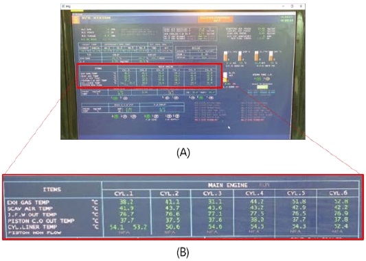
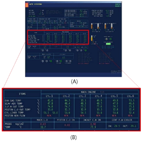
Experiment 1 used a small computer to capture images and perform character recognition. Figure 2(a) is an AMS image taken using a small computer and camera, and Figure 2(b) shows indicated cyl. information of the main engine in the AMS and an enlarged image of the parts to be extracted from this experiment through letter recognition.
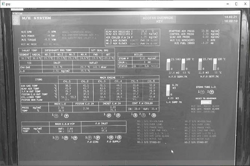
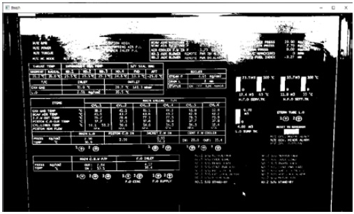
The original image was converted into a grayscale image by pre-processing using the OpenCV library, as shown in Figure 3.
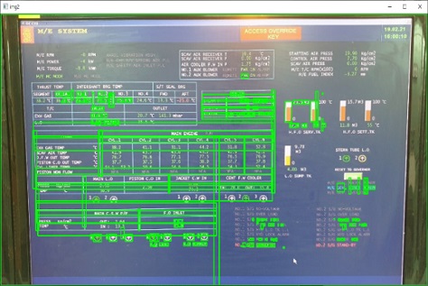
The boxed image in Figure 4 indicates the character recognition region from the grayscale image.
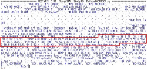
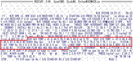
Figure 5 shows the results of character recognition based on the images in Experiment 1. This is the result of displaying the parts of the Tesseract Engine, which were recognized as character areas in Figure 4, except for parts that were not recognized by the Tesseract Engine. The red box in Figure 5 indicates the cylinder information recognized from the AMS through image processing.
Table 1 shows the comparison results of the original data with the string extracted through character recognition in Figure 5. Table 1(a) represents the result value of the original image in experiment 1, and Table 1(b) shows the results extracted through character recognition.
Experiments showed that accurate identification of characters was not possible, and 17 out of a total of 31 items were normally identified for numbers, with approximately 54.8 % identified. While the recognition of letters and numbers is typically achieved, the image shows a decrease in recognition rates for decimal points or special characters with small pixel sizes. It was not possible to identify a ship monitoring screen using images created by the camera. In addition, the light reflection of the screen, the resolution of the monitor and camera, and the vibration of the ship are combined to reduce the recognition rate. Figure 6 shows the results of pre-processing the grayscale image relative to the threshold point in order to verify reflection by the monitor during image acquisition.
3.2 Experiment 2: Extracting text from images created using screen capture tools.
Experiment 2 was conducted by capturing images displayed on a monitor; images were not obtained through external cameras. We used the same Python script as in Experiment 1.
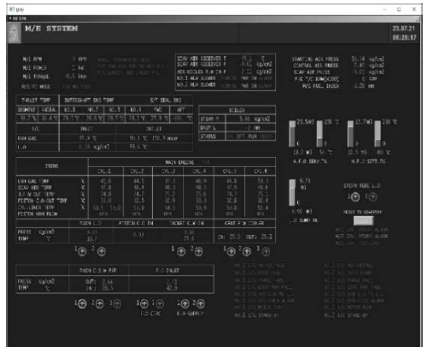
Figure 7(a) is an image taken using the screen capture program, and Figure 7(b) is an enlarged image of only the parts to be extracted from this experiment through character recognition.
Figure 8 shows the original image taken with the capture program that was pretreated using the OpenCV library and converted into a grayscale image. The results of extracting the data based on the captured images and removing spaces are shown in Figure 9.
Table 2 shows the comparison results of the original data with the string extracted through character recognition from Figure 9.
In Experiment 2, the overall alphabet was identified, but it was not possible to accurately identify special characters or symbols. However, 25 out of 31 items were normally identified, confirming that approximately 80.6% were identified. We can see higher recognition rates in English and numbers than in Experiment 1.
4. Conclusion
In this study, data extraction in an AMS monitor was performed by applying an OCR to study the autonomous surface ship platform method of existing vessels using image processing.
From the experimental results, we achieved a higher recognition rate in high-definition and high-resolution images, but given that the recognition rates for English and special characters are still low, it is expected that autonomous surface ship platforms using image processing should provide better resolution images. Further research should be conducted to obtain a better resolution for OCR-based data extraction, as accurate monitoring of ship status is very important for navigation safety even at remote locations. Furthermore, it is expected that research will be required on data extraction methods via on-board data hooking for onboard monitoring rather than image processing.
Author Contributions
Conceptualization, Y. S. Song; Methodology, Y. S. Song and B. S. Kim; Software, Y. S. Song; Formal Analysis, J. S. Kwon; Investigation, Y. S. Song; Resources, J. H. Noh; Data Curation Y. S. Song; Writing-Original Draft Preparation, Y. S. Song; Writing-Review & Editing, S. W. Choi and J. H. Yang; Visualization, J. H. Yang; Supervision, J. H. Yang.
References
-
A. Felski and K. Zwolak, “The ocean-going autonomous ship - challenges and threats,” Journal of Marine Science and Engineering, vol. 8, no. 1, p. 41, 2020.
[https://doi.org/10.3390/jmse8010041]

-
J. de Vos, R. G. Hekkenberg, and O. A. V. Banda, “The impact of autonomous ships on safety at sea – A statistical analysis,” Reliability Engineering & System Safety, vol. 210, 2021.
[https://doi.org/10.1016/j.ress.2021.107558]

-
M. Suri, “Autonomous vessels as ships – the definition conundrum,” IOP Conference Series Materials Science and Engineering, vol. 929, 2020.
[https://doi.org/10.1088/1757-899X/929/1/012005]

-
A. Miller, M. Rybczak, and A. Rak. “Towards the autonomy: Control systems for the ship in confined and open waters,” Sensors, vol. 21, no. 7, p. 2286, 2021.
[https://doi.org/10.3390/s21072286]

- J. Poikonen, M. Hyvonen, A. Kolu, T. Jokela, J. Tissari, and A. Paasio, Remote and Autonomous Ships—The Next Steps, https://www.rolls-royce.com/~/media/Files/R/Rolls-Royce/documents/customers/marine/ship-intel/aawa-whitepaper-210616.pdf, , Accessed December 1 2019.
-
I. Tawiah, U. Ashraf, Y. Song, and A. Akhtar, “Marine engine room alarm monitoring system,” International Journal of Advanced Computer Science and Applications, vol. 9, no. 6, 2018.
[https://doi.org/10.14569/IJACSA.2018.090659]

-
J. C. Trinder, “Digital image processing–The new technology for photogrammetry,” Australian Surveyor, vol. 39, no. 4, pp. 267-274, 2012.
[https://doi.org/10.1080/00050329.1994.10558460]

-
J. -W. Kim, S. -T. Kim, J. -Y. Yoon, and Y. -I. Joo, “A personal prescription management system employing optical character recognition technique,” Journal of the Korea Institute of Information and Communication Engineering, vol. 19, no. 10, pp. 2423-2428, 2015 (in Korean).
[https://doi.org/10.6109/jkiice.2015.19.10.2423]

-
J. Ma, W. Shao, H. Ye, L. Wang, H. Wang, Y. Zheng, and X. Xue, “Arbitrary-oriented scene text detection via rotation proposals,” IEEE Transactions on Multimedia, vol. 20, no. 11, pp. 3111-3122, 2018.
[https://doi.org/10.1109/TMM.2018.2818020]


