Application of educational simulator of two-stroke marine diesel engine
Copyright © The Korean Society of Marine Engineering
This is an Open Access article distributed under the terms of the Creative Commons Attribution Non-Commercial License (http://creativecommons.org/licenses/by-nc/3.0), which permits unrestricted non-commercial use, distribution, and reproduction in any medium, provided the original work is properly cited.
Abstract
This study reports on the development of a training simulator for low-speed marine two-stroke diesel engines for learning about the knowledge of diesel engines required for ship engineers through the Standards of Training, Certification, and Watch-Keeping for Seafarers (STCW) Convention of the International Maritime Organization (IMO) model courses 7.02 and 7.04. In consideration of the learning subjects, the program is divided into contents for operation-level, management-level, and graduate school-level training for the design of engines by changing the group of engine parameters that can be adjusted. According to the adjustment of the input parameters, this program can describe the output, specific fuel oil consumption (SFOC), temperature and concentration of exhaust emissions, cylinder pressure, performance of the turbocharger, and output values such as P-V and P-T diagrams. In addition, NOx calculations are programmed to provide access to the environmental issues caused by NOx, which have recently become an issue, from an engine design perspective. Based on the requirements of the STCW and model courses, this study confirms that the developed simulator can sufficiently simulate what is required at each stage and help with learning and research, by organizing learning scenarios and using simulators to derive results.
Keywords:
Marine, Two-stroke, Diesel engine, Simulator, Modeling1. Introduction
The International Maritime Organization (IMO) presents the qualifications and training standards for sailors aboard ships through the Standards of Training, Certification, and Watch-Keeping for Seafarers (STCW) Convention. Articles A-III/1 and A-III/2 and A-III/3 of the STCW Convention provide the criteria for the minimum functions for operation-level engineers in charge of watch keeping, for management-level engineers with propulsion units of more than 3,000 kW, and for management-level engineers with propulsion units of more than 750 kW and less than 3,000 kW.
The Convention calls for knowledge of the operation control method of the ship’s diesel engine and the thermodynamics of the diesel engine for the management-level engineer. In addition, the details of the training requiring operation- and management-level engineers are further defined in IMO model courses 7.02 and 7.04.
As the STCW Convention requires both theoretical and practical knowledge such as on the operation and maintenance of diesel engines, it is an effective way to combine theoretical and hands-on education. Among the curricula currently being implemented in Korea's maritime education institutions, the teaching methods for diesel engines can be divided into theoretical education, practical training by workshop and training ship, and training using a simulator. As the training on the ship is operated within the regular curricula of maritime high schools, maritime colleges, and the maritime institute, those who want to become seafarers may not have the opportunity to experience the training on the ship. Engine room simulator (ERS) training is the way that can be presented to overcome these limitations. As there is no locally developed ERS equipment, the cost of education is high mainly because expensive equipment developed abroad, such as by Kongsberg [1], Transas [2], and ARI, are imported and used mainly for the training of marine engineers. In addition, training using a training ship and ERS is considered to be very efficient in training for the operation of diesel engines, but rather insufficient for learning and understanding the kinematics and thermodynamic principles of diesel engines on their own. Because the main engine of an ocean-going vessel mainly uses low-speed two-stroke diesel engines because of their high propulsion efficiency, it is necessary for the trainees of the maritime education institution to focus on low-speed two-stroke diesel engines.
Performance prediction models and simulations for improving the performance of diesel engines have been studied very actively until recently [3]. Recently, the development of simulations for diesel engine performance prediction and fault diagnosis using artificial intelligence has been actively conducted [4]-[6]. However, there is no program that can provide practical training in the form of a simulation on the mechanical and thermodynamic principles of a marine two-stroke diesel engine.
This study aims to adopt an educational simulation program for marine two-stroke diesel engines so that the subject can learn the operation and theory of diesel engines on his own. Considering the learner's level, the program divides the groups of variables that can be controlled by the learner according to their level of education into classes for operation- and management-level engineers, and for designing engines at postgraduate or higher levels.
This program can check the output of diesel engines and the specific fuel consumption, temperature of exhaust gases and the concentration of exhaust emissions, compression pressure of cylinders and maximum explosive pressure, performance of the turbocharger, and output values such as P-V and P-T diagrams according to the adjustment of the input variables. In addition, NOx calculations are programmed to provide access to environmental issues caused by NOx, which have recently emerged from an engine design perspective. This study introduces the calculation model of the marine two-stroke diesel engine simulation program, the configuration of the scenario for education, and the application of the scenarios.
2. Modelling for Marine Two-Stroke Diesel Engine
To simulate the kinetic process of the engine, the expression of the movement of the piston is necessary, and thermodynamic equations are used to calculate the changes in the kinetics and gas flow and state. The marine two-stroke diesel engine adopts the uniflow scavenge method. It is composed of a scavenging port and an exhaust valve for intake and discharge of the working gas, and a fuel injector is attached to the cylinder cover for fuel injection.
To simulate the mechanical process of diesel engines, it is necessary to make simplified models for the compression, combustion, expansion, and exhaust processes. The filling and emptying air flow model is used to simulate the intake and discharge process of the working fluid during the scavenging and exhausting process. The thermodynamic state equation of the gas and Annand coefficient are used to calculate the loss owing to compression, simulation of the expansion process, and heat transfer during the process. In addition, the combustion process for heat flow into the cylinder is simulated using a double Weibe function [7]. To calculate the generation of emissions by the combustion process, the two-zone model [8]-[11] that divides the combustion chamber area into burned and unburned areas is used.
2.1 Air Flow Model
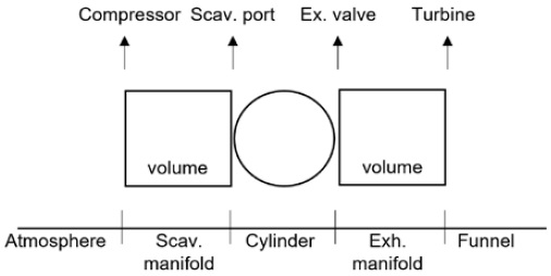
The target model of this program is a low-speed marine two-stroke engine, and has a manifold in the intake system. Therefore, to describe the air flow of a marine two-stroke engine, a filling and emptying model that approximates the volume of the intake and exhaust relationship and the cylinder, etc. is used. Figure 1 shows a conceptual diagram of the filling and emptying model. Air from the atmosphere enters the cylinder through the manifold, and the gas from the cylinder is released into the atmosphere through the exhaust manifold.
The air and gas velocity through the scavenging port and exhaust valve are as follows:
| (1) |
| (2) |
The gas flow rate can be calculated as follows:
| (3) |
| (4) |
| (5) |
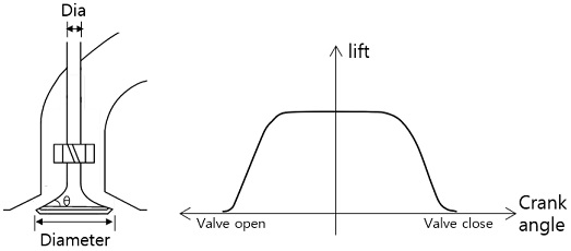
The flow coefficient (Ca) of the scavenging port is applied differently according to the shape of the port and degree of opening of the port as shown in Figure 2, and the flow coefficient of the exhaust valve (Ce) is applied differently according to the valve lift, as shown in Figure 3 [12].
The opening area of the scavenge port is determined by the overall length and width of the port and the position of the piston at the bottom dead center. It is calculated as follows from the relationship with the lower part of the port. The crown surface of the piston at the bottom dead center is expressed as the relative position (X0) with the lower part of the port. Also, the top and bottom of the port are treated as a semicircle with the port width as the diameter.
- 1) 0 < t < r
| (6) |
| (7) |
- 2) r ≤ t ≤ H − r
| (8) |
- 3) H − r ≤ t < H − X0
| (9) |
| (10) |
To calculate the flow rate of the working gas escaping through the exhaust valve, the area of the valve by the angle of the valve seat is calculated as follows:
| (11) |
As shown in Figure 3, the data of the valve lift inputs each crank angle and the lift at that position in the direction from the exhaust valve opening angle to the crank angle.
The compression work in the compressor and turbine work (expansion work) in the turbine can be obtained from relational expressions as follows:
| (12) |
| (13) |
It is assumed that the condition of the compressor outlet is constant. The condition of the turbine inlet is the same as that of the exhaust receiver. The instantaneous state of the turbine is calculated from the state of the exhaust receiver. The turbine work can be calculated by integrating the state values for one cycle. However, the efficiency of the turbine is assumed to be constant.
2.2 Combustion Model
Because diesel engines are injected with fuel near the top dead center, the process of forming a mixture of air and fuel is very complex. The reason for this is that in the process of fuel injection and evaporation, the process of forming a mixture by the air flow affects the combustion; correspondingly, many theoretical models have been studied [13]-[15].
In the generation of combustion products, the temperature and mixing ratio of the mixture of air and fuel in the combustion chamber are closely related [16]. Therefore, it is necessary to treat combustion chamber areas separately, i.e., as several areas. The larger the number of areas separating the combustion chambers, the more precise the calculations; here, the two-zone model, divided into a burned and an unburned area, is adopted. The two-zone model assumes that the mixing gas in the cylinder is divided into two areas separated by a surface of discontinuity. The temperatures and gas compositions in the two areas are different, and the pressure is assumed to be the same. Therefore, it is suitable for the calculations for combustion products greatly affected by temperature.
The two-zone model distinguishes between the combustion zone and unburned zone. The variables to represent the state of the two regions are P, Vb, Vu, Tb, and Tu, and five relational equations are required. The derivation process for calculating each variable is omitted, and the resulting equations are as follows:
| (14) |
Each letter used in the equation is determined as follows:
| (15) |
| (16) |
| (17) |
| (18) |
| (19) |
| (20) |
| (21) |
| (22) |
| (23) |
The initial temperature of the combustion zone at the start of heat generation, assuming the adiabatic combustion temperature using the initial value of the excess air rate, is calculated as follows.
| (24) |
The combustion process of the compression ignition engine is explained in four sections: the ignition delay period, non-controlled combustion period, control combustion period, and post-combustion period. During the ignition delay period, the fuel evaporates and breaks up into micro droplets, and the droplets mix with air to form a mixing gas. Then, the mixing gas begins a chemical reaction. The rapid or uncontrolled combustion period is when the air fuel mixture formed during the ignition delay period is ignited, resulting in very fast pressure increases and high heat generation. This period greatly affects the generation of NOx, which is sensitive to the combustion temperature. The control combustion period starts combustion from the mixture of the prepared fuel and the air, and the combustion period and condition are adjusted according to the amount of fuel mixed with the air. The heat generation by combustion lasts until the post combustion period.
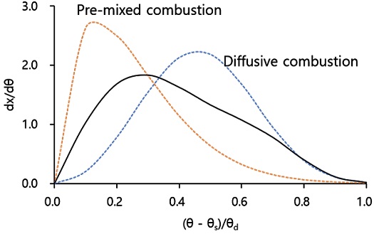
Therefore, the heat release rate generated by burning the fuel inside the cylinder is simulated using the Wiebe function. Also, to describe the actual engine, as shown in the Figure 4, it is divided into pre-mixed combustion and diffusive combustion, and the heat release is simulated by the double Wiebe function [17][18].
Wiebe function:
| (25) |
Double Wiebe function:
| (26) |
| (27) |
Fpre and Fdif are the ratios of pre-mixed and diffusive combustion, and Fpre + Fdif = 1.
2.3. NO Calculation Model
The Zeldovich mechanism, in which NO is produced from nitrogen in the atmosphere, is generally the best applicable to combustion systems in an air-fuel mixture. Therefore, it is possible to perform the combustion model for the NO calculation by using the Zeldovich mechanism. The combustion zone in the cylinder is divided into two areas, burned and unburned, and the emission is calculated by applying the Zeldovich mechanism, assuming that the mixing conditions are uniform within each area.
When the hydrocarbon fuel CmHn is reacted with air, only O2, N2, CO2, and H2O are produced and discharged in case of complete combustion, but in reality, complete combustion does not occur, and dissociation is caused by the high-temperature combustion gas. That is, CO2, H2O, and O2, which are complete gas components, cause dissociation, and the H2 and O2 generated by this dissociation stop while causing dissociation again.
At the beginning of combustion, the temperature of the gas in the combustion chamber is low; this is different from the rapid combustion pattern during the main combustion period, and causes a different type of reaction. When the combustion gas is less than 1000 K, only CO2, H2O, N2, O2, CO, and H2 are generated, and in the range of 1000–3000 K, 10 components (CO2, H2O, N2, O2, CO, H2, H, O, OH, NO) are considered [19].
The equilibrium calculation method is a method of calculating the number of moles of each product using the law of conservation of mass and the equilibrium constant under a given temperature and pressure.
In this study, only 10 components (CO2, H2O, N2, O2, CO, H2, H, O, OH, NO) were considered. When the diesel fuel CnHm with an equivalent ratio of ∅ is chemically reacted, it is expressed by a reaction equation as follows:
| (28) |
From the reaction equation above, using the law of conservation of mass, five equations can be derived by using the equation, in addition to the relationship with the total number of moles using the mole fraction yi. By assuming a chemical reaction in which CO2, H2O, N2, and O2 generate CO, H2, H, O, OH, and NO by dissociation, six relational expressions can be obtained by using this relation. That is, in the above dissociation reaction, the equilibrium constant K at which these reactions are in equilibrium where the reverse reaction and the forward reaction rate are balanced can be obtained as follows:
| (29) |
| (30) |
| (31) |
| (32) |
| (33) |
| (34) |
The equations can be solved by determining the values of the equilibrium constants K1–K6 with the above six reaction equations. The equilibrium constant K is a function of the temperature only, and the following approximation equation presented by Olikara and Borman is used [20]. The constants K1–K6 of Equations (29)-(34) and A to E of Equation (35) are shown in Table 1.
| (35) |
T is the absolute temperature, and each coefficient is shown in Table 1 in the range of 600 K < T < 4000 K.
As the energy generation reaction rate in the flame side of the cylinder proceeds very quickly and the burned gas is close to thermodynamic equilibrium, the results of the equilibrium calculation for the temperature and pressure can be used. However, as the NO generation rate is generally much slower than the generation rate of other emission components, the calculation for NO should be calculated at non-equilibrium. There are many reactions for producing nitrogen oxides in the combustion chamber, but the fastest and most dominant is the Zeldovich mechanism. The extended Zeldovich mechanism used in the calculation of the NO production at non-equilibrium uses a chemical reaction equation as follows:
| (36) |
| (37) |
| (38) |
The rate constant of the extended Zeldovich reaction equation is shown in Table 2, and the rate constant is expressed as a function of temperature only.
If the forward reaction rate constant is k+ and the reverse reaction rate constant is k- in the expanded Zeldovich mechanism reaction equation above, the NO production rates are expressed as follows:
| (39) |
| (40) |
| (41) |
| (42) |
| (43) |
| (44) |
3. Marine Two-Stroke Diesel Engine Simulator
3.1. Program Calculation Process
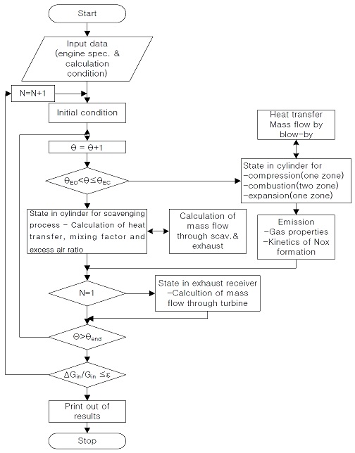
Figure 5 shows the calculation procedure for the diesel engine simulation program. For the operation of the simulation program, the initial inputs include the dimensions of the engine components (figure of physical shape of the cylinder, scavenge port, exhaust valve), operation data (rpm, brake horsepower (BHP), specific fuel oil consumption (SFOC), scavenge air pressure), and Wiebe index (prefixed and diffused) for the heat release rate. The concentrations of the pressure, volume, temperature, and gas components are then calculated in the following order: i) scavenging process, ii) compression process, iii) combustion process, iv) expression process, and v) emission according to the crank angle. Finally, the work of the turbines is calculated by the pressure, temperature, and mass flow of the gas in the process of expansion, and the efficiency of the turbocharger is calculated.
3.2. Simulator User Interface
This engine simulation program is designed to provide training for operation- and management-level engineers as required by the STCW, as well as for graduate students studying diesel engines.
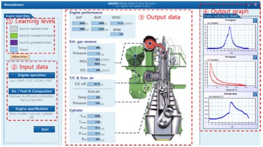
Figure 6 shows the user interface of a two-stroke diesel engine training simulator. In Figure 6, ① is an engine input data screen, and is divided into colors (gray, green, purple) according to the level of learning so that it can be divided into operation level, management level, and graduate school level. ② is an input data item and is classified into data on the engine operating conditions, air-fuel ratio, and engine dimensions. If the user clicks each item, the user can enter each numerical value in a pop-up window for it. ③ is the output for the result of the input, and the following items are included: i) engine performance (indicated horsepower (IHP), BHP, and SFOC), ii) exhaust gas conditions (temperature, pressure, NOx and CO2), iii) turbocharger and scavenge air (T/C efficiency, temperature, and pressure), iv) cylinder condition (temperature and pressure). ④ prints the results for the cylinder condition on pressure and theta (P-T), pressure and volume (P-V), and theta and temperature (T-T) graphs so that learners can easily understand the changes in engine conditions.
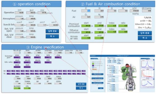
Figure 7 is a pop-up window for data input, and the colors of the items that can be entered are different for each learning level (operation level, management level, and graduate school level).
3.3. Standards of Training, Certification, and Watch-Keeping for Seafarers (STCW) and International Maritime Organization (IMO) Model Course 7.02 and 7.04
The STCW Convention specifies and enforces competency for operation- and management-level engineers in A-code, and recommends detailed education/training guides for competency as model courses. Table 3 shows the knowledge related to the diesel engine of the ship as required by the drivers at the STCW and model courses.
STCW A-III/1 is the competency required by the engineer for watch-keeping, and A-III/2 is the competency required by the management engineer. Model courses 7.04 and 7.02 denote the education/training required by the operation- and management-level engineer. In addition to the contents provided in Table 3, the convention and model courses include maintenance, repair, and planned maintenance related to diesel engines. Therefore, Table 3 shows only the contents of the education and training that can be performed using the simulation program. In the STCW Convention, the knowledge of the basic structure and operation of diesel engines from the operation level and the theoretical knowledge of the diesel engine from the management-level engineer are required. According to the model course, 100 hours of training are required for the basic structure and operation principle, and 50 hours of training are required for thermodynamics and heat transmission.
Table 4 shows the scenarios derived based on the required education content for the operation and management levels as classified in the STCW, and the level required for the graduate school course. The requirement of the operation level is the operation of the propulsion system necessary for being on duty. As necessary for the operation training of the engine, the relationship between speed and power can be drawn on a graph while adjusting the input data. The scenario for the management level is composed of the understanding of the combustion process, the understanding of the internal combustion engine cycle including the Diesel, Otto, and Sabathe cycles, and the understanding of the heat loss of the diesel engine. For graduate students who aim to study the design and performance improvement of diesel engines, a scenario is constructed so that they can know which design factors affect the performance of the engine, and which design factors of the T/C affect the engine performance. In addition, a scenario is constructed to enable research on the exhaust gas products emitted from diesel engines.
3.4. Application of the Scenario using the Simulator
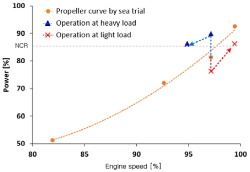
Figure 8 is the propeller curve according to the engine operation status expressed by the program according to the scenario 1 for the operating-class engineer.
The yellow mark
 is a propeller curve that expresses the speed and power at 50%, 70%, 80%, and 90% load, respectively, in the same sea conditions during sea trial operation of the model ship. The blue mark
 shows the process of driving by decelerating the speed to approximately 95% and reducing it to normal continuous rating power when the ship's resistance increases and the output increases to 90% in the operating state of 80% load. The red mark
 shows how the engine speed increases according to the load reduction when the resistance decreases in an operating state of 80% load. When operating on duty, the engineers should be able to respond to emergency situations such as torque rich, overload, and over-speed by identifying the load conditions of the main engine according to the resistance of the hull, and should be familiar with the speed increase and decrease methods for load fluctuations.
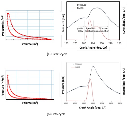
Figure 9 shows the P-V diagrams of the Diesel and Otto cycles corresponding to scenarios 2 and 3 in Table 4, and the combustion process by each cycle.
Figure 9(a) shows a typical diesel cycle. Through the heat release graph, it can be seen that the ignition delay period from fuel injection to ignition passes, leading to premixed combustion and diffusion combustion. Figure 9(b) shows the P-V diagram and heat release of the Otto cycle (represented by the static cycle). Through this graph, it is possible to observe the combustion process in a static state in which pressure and heat are instantaneously generated by burning all at once as the mixed air-fuel gas is ignited.
The STCW requires the ship's engineer at the management level to be familiar with the heat cycle and combustion process, and understanding the different combustion characteristics and combustion processes is a very important part of engine fault diagnosis and maintenance.
The jacket cooling water temperature should be maintained at an appropriate temperature to prevent damage to the cylinder liner, cylinder cover, and valves of the engine owing to overheating, and to improve stability and prevent corrosion. High jacket cooling water temperatures cause material cracking and heavy deposits of dirt and metallic particles. However, too low a temperature of the cooling water increases the heat loss escaping to the cylinder wall, and accelerates the corrosion by the marine fuel oil with a high sulfur content. Therefore, the temperature of the cooling water must be maintained at the appropriate temperature recommended by the engine manufacturer.
Table 5 shows the simulation results of the effect of the cooling water temperature on the engine performance in Scenario 4 in Table 4. The temperature of the cylinder liner is related to the friction between the piston ring and liner, affecting the performance and combustion temperature, and thereby affecting the generation of NOx and hydrocarbons [21].
The cylinder wall temperature is determined by the cooling water temperature and combustion chamber temperature. In the simulation, the combustion chamber temperature is performed under the same conditions to check the performance effect of the cooling water temperature on the cylinder wall. As the cooling water temperature gradually decreases from 90 °C, the compression pressure (Pcomp) also decreases, affecting the maximum pressure (Pmax) and maximum temperature (Tmax). This also affects the IHP and SFOC. Marine engineers are expected to be able to easily understand the effect of the coolant temperature on the engine performance for fuel reduction and power management through the simulation. Recently, research to reduce the NOx generated from diesel engines owing to the seriousness of global warming and particulate matter concentrations are ongoing [21]–[9][22][23]. In the area of diesel engines for marine use, the IMO is forcing ships built after January 1, 2016 to be equipped with facilities that can satisfy Tier III when sailing emission control areas, so technical studies are actively being conducted to reduce the NOx from the low-speed two-stroke diesel engines for ships [24][25].
According to the Zeldovich Mechanism, the NOx generated in the process of thermal dissipation of combustion gases is generated at temperatures above 1800 K and is greatly affected by the highest combustion temperature, and if the combustion temperature is reduced by 200 K, the NOx generation is reduced to one-tenth [26]. The factors affecting the combustion temperature and combustion process are the injection conditions, intake and exhaust conditions, and performance of the T/C. The impact of these factors on the NOx reduction can be seen through this simulation program.
Table 6 is the result of simulating the temperature and pressure of the scavenge air and the area of turbine nozzle under the same conditions by using the program to determine the effect of performance of the T/C on the engine and emission under the control of each variable corresponding to Scenarios 5 and 6.
Case 1 shows that the increased scavenge air pressure in ref. has resulted in improved engine performance such as in the IHP and SFOC, and the increased T/C efficiency has also affected the reduction of emissions. Case 2 shows that the effects of improving the performance and reducing emission can be achieved by lowering only the scavenge air temperature at Ref. Case 3 adjusted the area of turbine nozzle to adjust the flow rate of turbine. An increase in the turbine area causes a decrease of intake air pressure, owing to a decrease in the pressure at the turbine inlet. A small turbine area can improve the boost pressure, but increases the pumping loss at the same time because of high backpressure [27]. Therefore, to maintain performance, it is required to improve the compressor efficiency, that is, improve the overall T/C efficiency.
The efficiency of the T/C increases through the adjustment of variables in cases 1, 2 and 3, thereby reducing the Tmax of the combustion chamber. It can be seen that this leads to a decrease in NOx.
The IMO presents the emission factor of marine fuel through the 3rd greenhouse gas study [28]. In all cases, CO2 emissions can be calculated by applying an emission factor to the fuel consumption. In case 1 with the lowest SFOC, the absolute amount of CO2 may be calculated as the lowest. CO2 emissions are also affected by the T/C efficiency.
Through the marine two-stroke diesel engine simulator, it is possible to check the performance factors that affect engine performance and emission, and to know that engine design for engine performance improvement and emission reduction is also possible.
4. Discussion and Conclusions
This study is about the application of a marine diesel engine training simulator to facilitate an understanding of the diesel engine knowledge required by the STCW and IMO model courses.
The main engine of the ships currently in operation is a mechanical control engine, and the proportion of electronical control engines continues to increase. The difference between a mechanical engine and electronical engine is in the control method of the fuel and exhaust valve. The simulator needs to reflect the electronical control model of the fuel and valve by reflecting the recent trend. As this study constructs the scenarios in accordance with the requirements of the STCW, there is a limitation in applying the scenarios only in cases of the thermodynamics, without dealing with the contents of the fuel and valve control.
As all of the scenarios do not reflect actual data, situations that cannot actually appear may result. The clear purpose of the study is to understand the theoretical correlation while directly calculating the states of the engine performance and emission change according to variable changes; thus, it is judged to be useful for learning purposes, not for research purposes. However, it is necessary to upgrade the simulator through verification of the actual data, so that the data on the actual situation can be sufficiently reflected.
The marine two-stroke diesel engine training simulator aims to increase the accuracy of the results by using a calculation model suitable for a ship's two-stroke engine for each process, so that all processes (scavenging, compression, combustion, expansion, and exhaust) of the engine heat cycle can be simulated. It is designed to be able to calculate the emission from diesel engines, which is a recent issue, so that it is possible to educate not only the ship's engineer, but also the graduate school student who wants to design and research the engine. The user environment is configured so that the user can select and simulate engine variable items that can be input by learning levels into three stages (operation level, management level, and graduate school level). In this study, a learning scenario was constructed based on the content required in the STCW and Model courses, and the result value was derived using a simulator. Through this, it was confirmed that the developed simulator can sufficiently simulate the content required in each step, and can be helpful in learning and research. Through the application of this simulator, it is necessary to improve the theoretical education and engine research of the marine two-stroke diesel engine.
Acknowledgments
This work was supported by the National Research Foundation of Korea (NRF) grant funded by the Korea government (MSIT) (2021R1G1A1008612110) by the ‘Autonomous Ship Technology Development Program (K_G012001614001)’ funded by the Ministry of Trade, Industry & Energy (MOTIE, Korea).
Author Contributions
Conceptualization, J. W. Lee and W. J. Lee; Methodology, J. W. Lee; Formal Analysis, J. U. Lee and H. M. Baek; Data Curation, B. S. Roh and H. M. Baek; Writing Original Draft Preparation, J. W. Lee; Writing Review and Editing, J. W. Lee, K. Park and W. J. Lee; Funding Acquisition, J. W. Lee and W. J. Lee. All authors have read and agreed to the published version of the manuscript.
References
-
R. Laskowski, L. Chybowski, and K. Gawdzińska, An engine room simulator as a tool for environmental education of marine engineers, New Contributions in Information Systems and Technologies, Springer, pp. 311-322, 2015.
[https://doi.org/10.1007/978-3-319-16528-8_29]

-
S. V. Tarasov, D. V. Kiptily, D. V. Lebedev, “An object-oriented approach to the development of liquid cargo handling simulators in TRANSAS,” IFAC Proceedings Volumes, vol. 45, no. 2, pp. 369-373, 2012.
[https://doi.org/10.3182/20120215-3-AT-3016.00065]

-
G. Sujesh and S. Ramesh, “Modeling and control of diesel engines: A systematic review,” Alexandria Engineering Journal, vol. 57, no. 4, pp. 4033-4048, 2018.
[https://doi.org/10.1016/j.aej.2018.02.011]

-
A. Parlak, Y. Islamoglu, H. Yasar, and A. Egrisogut, “Application of artificial neural network to predict specific fuel consumption and exhaust temperature for a Diesel engine,” Applied Thermal Engineering, vol. 26, no. 8-9, pp. 824-828, 2006.
[https://doi.org/10.1016/j.applthermaleng.2005.10.006]

-
B. Ghobadian, H. Rahimi, A. M. Nikbakht, G. Najafi, and T. F. Yusaf, “Diesel engine performance and exhaust emission analysis using waste cooking biodiesel fuel with an artificial neural network,” Renewable Energy, vol. 34, no. 4, pp. 976-982, 2009.
[https://doi.org/10.1016/j.renene.2008.08.008]

-
F. Kimmich, A. Schwarte, and R. Isermann, “Fault detection for modern Diesel engines using signal- and process model-based methods,” Control Engineering Practice, vol. 13, no. 2, pp. 189-203, 2005.
[https://doi.org/10.1016/j.conengprac.2004.03.002]

-
T. Ganapathy, K. Murugesan, and R. Gakkhar, “Performance optimization of Jatropha biodiesel engine model using Taguchi approach,” Applied Energy, vol. 86, no. 11, pp. 2476-2486, 2009.
[https://doi.org/10.1016/j.apenergy.2009.02.008]

- M. Lee, Y. Kim, and K. Kim, “Two-zone Modeling for combustion process of HCCI Engine,” The Korean Society of Automotive Engineers, vol. 13, no. 3, no. 74-79, 2005.
-
C. D. Rakopoulos, D. C. Rakopoulos, G. C. Mavropoulos, and G. M. Kosmadakis, “Investigating the EGR rate and temperature impact on diesel engine combustion and emissions under various injection timings and loads by comprehensive two-zone modeling,” Energy, vol. 157, pp. 990-1014, 2018.
[https://doi.org/10.1016/j.energy.2018.05.178]

-
G. Gonca, B. Sahin, Y. Ust, A. Parlak, and A. Safa, “Comparison of steam injected diesel engine and Miller cycled diesel engine by using two zone combustion model,” Journal of the Energy Institute, vol. 88, no. 1, pp. 43-52, 2015.
[https://doi.org/10.1016/j.joei.2014.04.007]

-
S. I. Raptotasios, N. F. Sakellaridis, R. G. Papagiannakis, and D. T. Hountalas, “Application of a multi-zone combustion model to investigate the NOx reduction potential of two-stroke marine diesel engines using EGR,” Applied Energy, vol. 157, pp. 814-823, 2015.
[https://doi.org/10.1016/j.apenergy.2014.12.041]

- J. B. Heywood, Internal Combustion Engine Fundamentals, McGraw-Hill Education, 2018.
-
Y. Chen, X. Li, X. Li, W. Zhao, and F. Liu, “The wall-flow-guided and interferential interactions of the lateral swirl combustion system for improving the fuel/air mixing and combustion performance in DI diesel engines,” Energy, vol. 166, pp. 690-700, 2019.
[https://doi.org/10.1016/j.energy.2018.10.107]

-
X. Li, Y. Chen, L. Su, and F. Liu, “Effects of lateral swirl combustion chamber geometries on the combustion and emission characteristics of DI diesel engines and a matching method for the combustion chamber geometry,” Fuel, vol. 224, pp. 644-660, 2018.
[https://doi.org/10.1016/j.fuel.2018.03.063]

-
A. T. Calik, O. O. Taskiran, and R. Mehdiyev, “Numerical investigation of twin swirl application in diesel engine combustion,” Fuel, vol. 224, pp. 101-110, 2018.
[https://doi.org/10.1016/j.fuel.2018.03.049]

-
P. Prabhakaran, P. Ramesh, C. Saravanan, M. Loganathan, and E. J. Gunasekaran, “Experimental and numerical investigation of swirl enhancing grooves on the flow and combustion characteristics of a DI diesel engine,” Energy, vol. 115, no. 1, pp. 1234-1245, 2016.
[https://doi.org/10.1016/j.energy.2016.09.063]

-
Y. Shiao and J. J. Moskwa, “Cylinder pressure and combustion heat release estimation for SI engine diagnostics using nonlinear sliding observers,” IEEE Transactions on Control Systems Technology,” vol. 3, no. 1, pp. 70-78, 1995.
[https://doi.org/10.1109/87.370712]

-
N. Miyamoto, T. Chikahisa, T. Murayama, and R. Sawyer, Description and Analysis of Diesel Engine Rate of Combustion and Performance using Wiebe's Functions, SAE Technical Paper 850107, SAE International, USA, pp. 622-633, 1985.
[https://doi.org/10.4271/850107]

- C. R. Ferguson and A. T. Kirkpatrick, Internal combustion engines: Applied Thermosciences, John Wiley & Sons, 2015.
-
C. Olikara and G. L. Borman, A Computer Program for Calculating Properties of Equilibrium Combustion Products with Some Applications to IC Engines, SAE Technical Paper 750468, SAE International, USA, 1975.
[https://doi.org/10.4271/750468]

-
B. Ghobadian, H. Rahimi, A. Nikbakht, G. Najafi, and T. Yusaf, “Diesel engine performance and exhaust emission analysis using waste cooking biodiesel fuel with an artificial neural network,” Renewable Energy, vol. 34, no. 4, pp. 976-982, 2009.
[https://doi.org/10.1016/j.renene.2008.08.008]

-
Z. Wang, S. Zhou, Y. Feng, and Y. Zhu, “Research of NOx reduction on a low-speed two-stroke marine diesel engine by using EGR (exhaust gas recirculation)–CB (cylinder bypass) and EGB (exhaust gas bypass), International Journal of Hydrogen Energy, vol. 42, no. 30, pp. 19337-19345, 2017.
[https://doi.org/10.1016/j.ijhydene.2017.06.009]

-
M. N. Nabi, M. S. Akhter, and M. M. Z. Shahadat, “Improvement of engine emissions with conventional diesel fuel and diesel–biodiesel blends,” Bioresource Technology, vol. 97, no. 3, pp. 372-378, 2006.
[https://doi.org/10.1016/j.biortech.2005.03.013]

- M. Preem, IMO Tier III NOx technology status for large two stroke engines, Ship Efficiency, pp. 26-27, 2011.
- A. Azzara, D. Rutherford, H. Wang, Feasibility of IMO annex VI Tier III implementation using selective catalytic reduction, Int. Counc. Clean Transp, pp. 1-9, 2014.
- K. SUGIURA, Theoretical and experimental study on measures to minimize the NOx-SFC trade-off, CIMAC Congress 2010 Bergen, 2010.
-
I. Al-Hinti, M. Samhouri, A. Al-Ghandoor, and A. Sakhrieh, “The effect of boost pressure on the performance characteristics of a diesel engine: A neuro-fuzzy approach,” Applied Energy, vol. 86, no. 1, pp. 113-121, 2009.
[https://doi.org/10.1016/j.apenergy.2008.04.015]

- I. M. Organization, Third IMO GHG Study 2014, International Maritime Organization, London, 2015.

