Region-based massive positioning method using Bluetooth low energy
Copyright © The Korean Society of Marine Engineering
This is an Open Access article distributed under the terms of the Creative Commons Attribution Non-Commercial License (http://creativecommons.org/licenses/by-nc/3.0), which permits unrestricted non-commercial use, distribution, and reproduction in any medium, provided the original work is properly cited.
Abstract
Recently, owing to the increase in the “smartization” of large-scale conventions and manpower-intensive industries, a Bluetooth low energy (BLE) method using a beacon, i.e., a low-cost wireless communication system, is being actively researched for a positioning system. A BLE method uses a low-power device and has a large standard deviation of signal strength compared to other wireless communication methods, so it is not easy to estimate the location accurately. In addition, it is essential to consider the computation in a positioning system in a densely populated environment. Therefore, we propose a region-based massive positioning method using BLE that enables a densely positioning method by reducing the weight of the algorithm and resolving the standard deviation of the signal strength. The proposed method estimates the distance based on the log-distance path loss model, and creates a region of existing (ROE) that does not require the existing least-squares method. The ROE, which indicates the possibility of an object's existence, is weighted based on the signal strength, and the proposed method minimizes operations by stacking ROEs. Moreover, the location is estimated through ROE pooling. The proposed method has an average error distance of 4.8 m, and it is confirmed that the position accuracy is 96.27%, showing excellent performance.
Keywords:
BLE, Positioning system, Region of existing, Massive positioning, Log-distance1. Introduction
Recently, owing to casualties occurring at industrial sites, interest in the safety management of field personnel is increasing. In other fields, personnel management in an ample open space such as a construction site is complex, because the workspace and routine are variable. So, the management of a large area starts with accurately figuring out the worker's location. Building a positioning system suitable for each environment is necessary for a location-based service (LBS) that provides a place to such a user. An outdoor positioning system typically uses the Global Positioning System (GPS) based on a satellite system. Still, it is challenging to guarantee positioning accuracy in a city center where radio wave interference is severe, owing to the surrounding buildings. Therefore, research on a positioning system that can replace GPS locally is actively being conducted indoors and outdoors. In the early days, proximity-based methods such as Infrared and near-field communication were introduced for relatively simple tasks such as access control. Still, it is difficult for these devices to know the exact location of the user. Recently, Internet of Things devices have been widely used, mainly in smartphones. Accordingly, positioning systems based on short-range wireless communication such as Wi-Fi, ultra-wide band (UWB), and Bluetooth Low Energy (BLE) are being applied [1]-[7]. These methods are widely used because they can stack with the existing communication infrastructure.
However, the increase in the “smartization” of large conventions and manpower-intensive industries has increased the demand for massive positioning systems. Accordingly, existing research is being conducted in the direction of improving positioning accuracy. In particular, UWB is not suitable for large-scale positioning situations, because it requires an exact positioning system with an accuracy of several tens of millimeters, or a costly sensor. To increase the versatility of the positioning system, research using a universal Wi-Fi infrastructure or inexpensive BLE methods is active. A BLE method using a beacon has attracted attention, owing to minimizing the cost for system construction. It is difficult to estimate the location of a BLE device (a low-power device) accurately, because the standard deviation of the signal strength is larger than that of other methods. Algorithms that stabilize unstable radio signals to minimize signal deviation are being actively studied [8]-[13].
Representative positioning techniques are largely divided into two methods, trilateration, and fingerprint. As trilateration estimates the relative distance using the location information of the transceiver and the signal characteristics (delay, intensity) between the two, no particular prior work is required owing to environmental changes [14][15]. However, depending on the material of the structure and the non-line of sight (NLOS) environment, there is a vulnerability in that the signal becomes unstable. Owing to these characteristics, it is challenging to ensure positioning stability in complex industrial sites with many steel structures. A fingerprint is also applicable to the NLOS environment, because it collects all of the Received Signal Strength Indicators (RSSIs), the strengths of the radio signals in the service space, at regular intervals, and estimates the location based on the propagation pattern of each area [16]-[20]. However, if the structure of the service space changes, the collected propagation patterns cannot be reused, and must be newly constructed. As an industrial site depends on the progress of work, including the complex structures indoors and outdoors, a positioning system that can be operated independently of the environment is required.
Therefore, we propose a region-based massive positioning method using BLE for constructing a low-cost and massive positioning system applicable to industrial sites. The proposed method generates a region of existing (ROE), an area in which a positioning terminal can exist, based on the collected signal. Based on the log-distance path loss model, this ROE is used to analyze the BLE signal characteristics and select a possible area of existence. Moreover, by accumulating the ROEs generated by all beacon scanners, the possible positions in the reference space of positioning are estimated. This method minimizes the computations of existing algorithms, enabling fast positioning even in densely populated areas. In addition, as only the BLE characteristic of the reference space is analyzed and modeled, it does not require large-scale construction work such as with a fingerprint, and thus the construction cost can be minimized.
2. Related Theory
2.1 Path loss model of Bluetooth low energy (BLE)
Most of the trilateration techniques using BLE beacons directly convert the RSSI received from each scanner into a distance. The relative distance estimation method through RSSI uses the Friis formula, which expresses the attenuation according to the distance of radio waves in free space [21]-[24]. The attenuation signal strength PL(d) according to each distance is derived as follows:
| (1) |
In the above, d is the relative distance, λ is the signal's wavelength, and BLE follows the ISM band of 2.4 GHz. Equation (1) is a free space propagation model, and derives a log-distance path loss model that can be applied as an actual model according to the propagation characteristics. This path loss model calculates , the average received RSSI according to the distance, as follows:
| (2) |
Here, d0 refers to the far-field reference distance, and uses the path loss index n as the path loss at the reference distance. In real space, a loss owing to a shading effect occurs owing to structures such as surrounding walls, and thus the loss must be additionally considered. The log-normal model, which is the final path loss, can be derived as follows:
| (3) |
Xσ of the log-normal model means a Gaussian probability distribution with a standard deviation σ. It can obtain the relative position from the beacon scanner through this calculation process.
2.2 Device-based localization
RSSI-based positioning techniques are largely divided into mobile-based localization (MBL) and device-based localization (DBL) [4][25]. MBL estimates a user's location in a reference space using a mobile device such as a smartphone and anchor nodes. In most LBSs, MBL is often applied, but it is challenging to apply in industrial sites where an integrated positioning service needs to be operated, owing to the variety of devices and cost of individual terminals. Conversely, DBL is a method of estimating the user's location by analyzing the signal of the user's beacon with a central server through the scanner built into the infrastructure. A DBL-applied integrated positioning system has a low construction cost, but the server load increases as the number of people providing LBS increases. Therefore, it is necessary to consider the server's load to apply it to the recently enlarged conventions and smart systems.
3. Proposed Positioning Method
3.1 Overview of the proposed positioning method
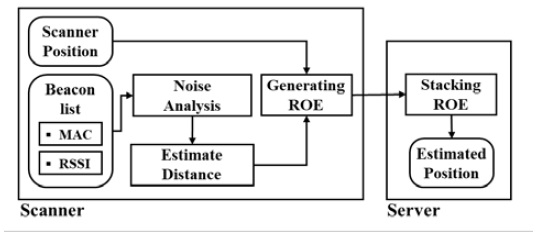
In this paper, we propose a region-based massive positioning method using BLE to build a low-cost, large-scale positioning system that can be directly applied to industrial sites. Unlike the general LBS operating environment, industrial zones have broad and complex spatial characteristics. These characteristics increase the cost of building a positioning system. In addition, a structure that changes according to the work schedule of the field makes it challenging to apply the existing mainstream fingerprint determination system. To solve this problem, in this study, DBL centered on the BLE beacon is used instead of the relatively expensive MBL to reduce the construction cost. In this DBL, as the load on the server increases as the number of service personnel increases, ROE stacking is applied to determine the existence of the target locally, so as to minimize this effect. Figure 1 shows the distributed processing method as proposed in a service space through scanners and servers.
As the proposed method applies the DBL approach, it consists of a user's terminal, multiple scanners in the reference space as shown in Figure 1, and the central server for location analysis. The scanner collects the MAC and RSSI signals of nearby beacons. It is possible to filter only the beacon(s) for positioning as preset through the beacon list. The proposed method analyzes the noise as a standard deviation using Equation (3) of the RSSI received to design the pass loss model. The standard deviation is reflected in the RSSI obtained in real-time, and the RSSI is converted into a distance through a pass loss model like in the conventional trilateration. We arranged Equation (3) as a distance-measured RSSI, which is derived as follows:
| (4) |
In the above, RSSI stands for the RSSI collected in real-time, and Xσ stands for the analyzed noise. By sending this to the server, the ROEs of all scanners are synthesized to obtain the final location information. Through this, the load of the server part can be distributed, and the amount of computation can be minimized.
3.2 Generating region of existing
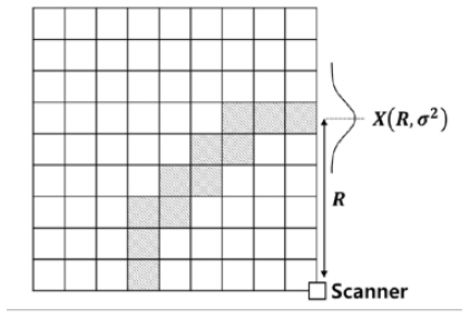
Trilateration, a representative positioning algorithm, estimates through the intersection of circles with three or more anchor nodes whose positions are known based on the calculated distance. This method is widely used, because it is intuitive and easy to implement. However, it is not easy to apply in an environment where the signal deviation is significant, such as in a BLE environment, because there is a case where the circles do not intersect. To solve this problem, the proposed algorithm estimates the location through the ROE. The ROE, like a fingerprint, divides the reference space into grids at regular intervals to store the possibility of the existence of an object. Figure 2 schematically illustrates the form and concept of the ROE.
The ROE is a matrix composed of real numbers mapped to a grid, with a circle with an estimated distance R centered on each scanner. In the case of Figure 2, the four quadrants are expressed as centered on the sensor. The ROE proposed in the natural environment is generated by substituting the coordinates of each scanner for the entire reference space. The area of the circle indicating the estimated position is determined based on the BLE propagation model. This ROE is generated individually for each scanner and sent to the server, as shown in Figure 1. The distance R, which is the circle's radius, can be calculated through Equation (4) with the measured RSSI. To generate the ROE, each scanner must have its coordinates checked in advance, and from these coordinates, it can accurately generate the grid. Equation (5) gives the equation of the circle projected on each ROE, as follows:
| (5) |
Here, xi and yi denote coordinates in the reference space of the scanner. As BLE has a significant standard deviation of the signal strength, the circle centered on R has a donut-shaped area, rather than a line. This phenomenon occurs more in a space where multiple fading is severe. We applied the log-normal path loss model of Equation (3) to apply these propagation characteristics to the ROE, and in this case, it defined the probability distribution to follow a Gaussian distribution.
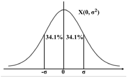
Figure 3 shows the Gaussian probability distribution, which means the probability at 1 σ. As the propagation characteristics of the environment in which the actual positioning system is constructed change according to the shape and material of each structure, a statistical analysis of the space is required. In the proposed algorithm, the circle is set as an area of 1 σ that can contain a majority signal of 68.2%. In this case, the upper and lower boundaries can be derived as Equations (6) and (7) through the standard deviation based on the measured RSSI, as follows:
| (6) |
| (7) |
The ROE can be composed of a straightforward binary matrix, because it denotes the space where an object is likely to exist on the grid. However, in a BLE environment, the closer the distance, the higher the reliability of the path loss model. Therefore, when there are many anchor nodes, the result may be biased to a location other than the location of the beacon. Thus, to reduce this bias, the collected RSSI was normalized to min-max, and the number to be input to the ROE grid was set. Equation (8) can be used to derive the value of the RSS ROE, as follows:
| (8) |
Here, min is the minimum of the collected RSSI, and max is the maximum of the collected RSSI. For each point of the ROE, the RSSI normalized to the inside of the boundary is input, and 0 is inputted to the outside and transmitted to the server. By processing this process in each distributed scanner, the load on the server is minimized.
3.3 Stacking region of existing and positioning
The ROEs generated by each scanner are transmitted and consolidated. As the normalized ROE has a value closer to 1 as the region with the highest probability of existence, the region with the highest probability of existence can be found by overlapping the ROE of the same beacon in all scanners. As this method consists of a simple matrix addition without calculations such as inverse matrix calculation or distance calculation between data, stable operation is possible even when positioning many people.
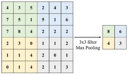
In most wireless communications, including those based on BLE, it is difficult to determine the actual difference in the RSSI at 1 m or less [15]. We set the grid to generate ROE as 1 m × 1 m. As a result, the location estimation through the initial grid can be very unstable. In addition, regions having a relatively large ROE may have a form in which they are scattered rather than continuous. It is an essential consideration, as a problem related to the reliability of the positioning system. We estimate the location by changing to a broader grid through ROE pooling.
Figure 4 is a conceptual diagram of the max pooling for ROE pooling. As the information of each grid refers to the possibility of existing in the corresponding space, it is downsampled by applying max pooling to maximize the likelihood. The user can adjust the size of the grid from 1 × 1 to 5 × 5 according to the setting of the environment initially. After that, the maximum position is detected based on the pooled ROE to estimate the position of the object. In this way, improved accuracy can be obtained.
4. Experimental and Results
4.1 Experimental environment
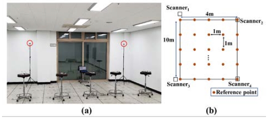
In this study, to prove the validity of the proposed method, we collected and tested the RSSIs at each location of the BLE equipment in a natural environment. As shown in Figure 5(a), we measured the experiment at intervals of 1 m in a space of 5.0 m × 12.0 m in Room 604 of the KMOU Research Complex. Figure 5(b) shows the locations of the installed four scanners and 55 reference points at 1-m intervals. We set the height of the scanner to 1.8 m in consideration of the general AP installation location, and we put the beacon to 1.0 m in a review of the height of the human hand. For the experiment, the sensor of the scanner was CHIPSEN's BoT-nLE521. We measured the RSSI of the beacon 100 times per one reference point (RP) through four scanners. In addition, we simultaneously collected beacon data five times during one measurement, for stable measurement. In general, scanners are often installed in locations other than the RP. However, the proposed method required an experiment for generating a path loss model in the offline stage. Therefore, the actual path loss model was derived through scanner 1 in Figure 5(b) in this experiment.
4.2 Analysis of path loss model and region of existing generation
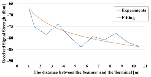
The proposed method uses model-based distance estimation. Therefore, to generate the ROE, we needed to know the log-distance path loss model from Equation (2). This study selected the path coefficient 1.665 through curve fitting to determine the path loss model for the ROE. Figure 6 is a graph comparing the actual measured RSSI of scanner 1 and the RSSI of the path loss model. The x-axis represents the distance from the scanner, and the y-axis represents the RSSI. In Figure 6, the blue line is the measured RSSI, and the orange line is the estimated model. The log-distance path loss model derived through this is as follows:
| (9) |
In the above, d0 is the far-field reference distance of the BLE environment, and d0 is obtained as follows:
| (10) |
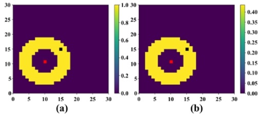
Here, D is the length of the antenna, generally 1/2 of the wavelength, and λ is the wavelength of BLE. As the frequency of BLE is 2.4 GHz, wavelength is 0.125 m, and length of the antenna is 0.06 m, d0 is 0.0576 m. As the far-field had the same waveform, the reference distance of the path loss model was more than 0.06 m. Therefore, in this study, the far-field reference distance was calculated as 1 m for the convenience of calculation [26]. Figure 7 shows the generation of the ROE through the proposed method when the RSSI is -76.5 dBm.
In Figure 7, the red dot at the (10, 11) position is the position of scanner 1, and the black dot at the (15, 15) position is the beacon's position. The yellow part formed around the scanner's position is the grid value of the ROE, and is composed of the binary ROE and RSS ROE of Equation (8). It can be seen that the actual number is changed through the legend on the right. We can estimate the exact position through the ROE in Figure 7(b).
4.3 Positioning experimental results
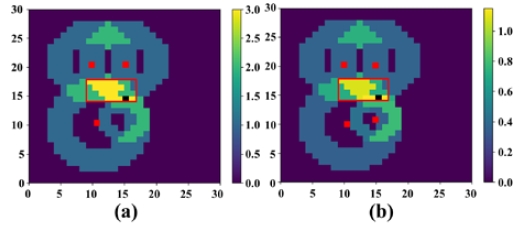
The ROEs collected from the scanner were stacked through the server, and the position was estimated by performing matrix sum. The grid with the highest value among the grid values of the stacking ROE was the position we estimated. Figure 8 shows the stacking ROE when the beacon position was (15,15). It is a heat map of the ROE that stacks the ROEs generated by each scanner. The red dots are the positions of the scanners, and the black dots are the positions of the measured beacons. Figure 8(a) is the stacking binary ROE, and Figure 8(b) is the stacking normalization ROE. At this time, the yellow pixel of the red bounding box is the portion having the highest value in the heat map, and is the location of the BLE beacon as estimated through the ROE. Here, the number of yellow pixels is 18 for the stacking binary ROE, and four for the stacking normalization ROE. This phenomenon, in which the remaining 14 pixels in Figure 8(b) have a smaller grid value owing to the normalization weight, solved the bias.
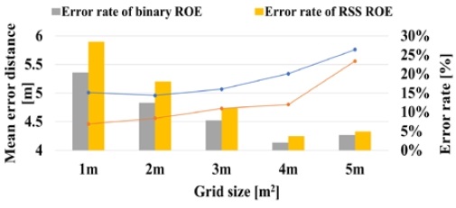
Figure 9 confirms the performance change of the mean error distance and error rate according to the grid size to find the optimal ROE pooling size. The X-axis is the result of ROE pooling according to the grid size, and the left Y-axis is the mean error distance corresponding to the line graph. The right Y-axis corresponds to the bar graph as the error rate. The mean error distance was obtained through the location of the BLE beacon and Euclidean distance by getting the midpoint of the result of the stacking ROE. The error rate was set to True if the coordinates of the BLE beacon were included in the ROE result, and set to False if not, to obtain the ratio of the number of True. Looking at the results of applying ROE pooling, the mean error distance increased gradually and sharply from 5.34 m and 4.8 m to 5.76 m and 5.56 m in a 5 m × 5 m grid for the binary and RSS ROE, respectively. Also, if the error rate was checked, the performance was significantly improved from 92.18 % and 88.95 % to 97.98 % and 96.27 % in a 4 m × 4 m grid, respectively. Therefore, the optimal grid size for ROE pooling was 4 m × 4 m.
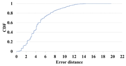
Figure 10 shows the error distance in the case of 4 m × 4 m ROE pooling using a cumulative distribution function (CDF). The X-axis is error distance, and the Y-axis is the CDF. The mean error distances were 5.34 m and 4.8 m, respectively. The mean error distance of trilateration using the same path loss model was 5.20 m, which did not show a significant performance difference of 0.14 m from the binary ROE. Still, the normalization ROE showed a performance difference of 0.4 m.
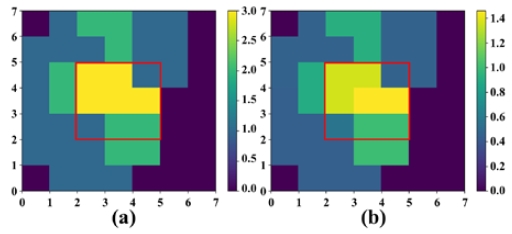
Figure 11 shows the results of Figure 8 when 4 m × 4 m ROE pooling is performed. Similarly, the yellow pixel in the red bounding box is the location where the location of the BLE beacon is most likely to exist. Through the 4 m × 4 m grid ROE pooling, we increased the probability of including the location of the BLE beacon. The number of pixels in Figure 11(a) is five, and the number in Figure 11(b) is two. As a result of ROE pooling, the accuracy values were 97.98% and 96.27% for the binary and RSS ROE, respectively, showing excellent performance.
Table 1 shows the error distance and accuracy of the test results in the experimental space through this method. As the grid size increased, the error distance increased by 0.33 m from 4.47 m to 4.8 m. Through the proposed method, it is possible to check the existence of Bluetooth low energy (BLE) beacons in the grid with high accuracy, and massive positioning through simple calculations is also possible.
5. Conclusion
In this paper, a large-scale positioning DBL method using BLE beacons (one of the short-range wireless communication positioning systems) was proposed. Trilateration and fingerprinting, which are conventional positioning techniques, consume a lot of time owing to complicated calculations and radio map matching when performing large-scale positioning. The proposed method analyzes the characteristics of the BLE beacon based on the log-distance path loss model in the scanner to generate the ROE, which is the area of the BLE existence and locates it using operation of minimization through the stack in the server. As a result of location recognition through the ROE, 4 m x 4 m ROE pooling compared to the existing trilateration improved the mean error distance by 0.4m and showed a high accuracy of 96.27 %. In addition, it was confirmed that the operation speed of ROE Stacking was increased by 52 %.
In the future, based on this study, we plan to study an onboard real-time monitoring system. If Wi-Fi with a relatively broad reach is used, it is judged that it will be a positioning method that enables large-scale positioning in a wide range through the ROE.
Acknowledgments
This work is supported by the Korea Agency for Infrastructure Technology Advancement (KAIA) grant funded by the Ministry of Land, Infrastructure and Transport (Grant 21CTAP-C163904-01). This work was supported by the National Research Foundation of Korea (NRF) grant funded by the Korea government (MSIT) (No. NRF-2021R1A2C1014024).
Author Contributions
Conceptualization, S. H. Lee; Methodology, S. B. Jeong; Soft-ware, S. B. Jeong and Y. J. Shin; Data curation S. B. Jeong and S. H. Lee; Writing-Original Draft Preparation, S. B. Jeong; Writing-Review & Editing, J. H. Seong and D. H. Seo; Supervision, D. H. Seo.
References
-
P. Davidson and R. Piché, “A survey of selected indoor positioning methods for smartphones,” IEEE Communications Surveys & Tutorials, vol. 19, no. 2, pp. 1347-1370, 2017.
[https://doi.org/10.1109/COMST.2016.2637663]

-
H. Liu, H. Darabi, P. Banerjee, and J. Liu, “Survey of wireless indoor positioning techniques and systems,” IEEE Transactions on Systems, Man, and Cybernetics, Part C (Applications and Reviews), vol. 37, no. 6, pp. 1067-1080, 2007.
[https://doi.org/10.1109/TSMCC.2007.905750]

-
S. Gezici, “A survey on wireless position estimation,” Wireless Personal Communications, vol. 44, no. 3, pp. 263-282, 2008.
[https://doi.org/10.1007/s11277-007-9375-z]

-
G. Deak, K. Curran, and J. Condell, “A survey of active and passive indoor localisation systems,” Computer Communications, vol. 35, no. 16, pp. 1939-1954, 2012.
[https://doi.org/10.1016/j.comcom.2012.06.004]

-
J. H. Seong and D. H. Seo, “Environment adaptive localization method using Wi-Fi and Bluetooth low energy,” Wireless Personal Communications, vol. 99, no. 2, pp. 765-778, 2018.
[https://doi.org/10.1007/s11277-017-5151-x]

-
W. Y. Kim, H. C. Zin, J. C. Kim, D. S. Noh, and D. H. Seo, “A study on 3-D indoor localization based on visible-light communication considering the inclination and azimuth of the receiver,” Journal of the Korean Society of Marine Engineering, vol. 40, no. 7, pp. 647-654, 2016 (in Korean).
[https://doi.org/10.5916/jkosme.2016.40.7.647]

-
W. Y. Kim, S. G. Park, W. H. Cho, D. S. Noh, and D. H. Seo, “A study on indoor visible light communication localization based on Manchester code using walsh code,” Journal of the Korean Society of Marine Engineering, vol. 39, no. 9, pp. 959~966, 2015 (in Korean).
[https://doi.org/10.5916/jkosme.2015.39.9.959]

- Z. Ma, S. Poslad, J. Bigham, X. Zhang, and L. Men, “A BLE RSSI ranking based indoor positioning system for generic smartphones,” 2017 Wireless Telecommunications Symposium (WTS), IEEE, pp. 1-8, 2017.
-
G. M. Mendoza-Silva, M. Matey-Sanz, J. Torres-Sospedra, and J. Huerta, “BLE RSS measurements dataset for research on accurate indoor positioning,” Data, vol. 4, no. 1, p. 12, 2019.
[https://doi.org/10.3390/data4010012]

-
M. Atashi, P. Malekzadeh, M. Salimibeni, Z. Hajiakhondi-Meybodi, K. N. Paltaniotis, and A. Mohammadi, “Orientation-matched multiple modeling for RSSI-based indoor localization via BLE sensors,” 2020 28th European Signal Processing Conference (EUSIPCO), IEEE, pp. 1702-1706, 2021.
[https://doi.org/10.23919/Eusipco47968.2020.9287489]

-
S. Sadowski and P. Spachos, “Optimization of BLE beacon density for RSSI-based indoor localization,” 2019 IEEE International Conference on Communications Workshops (ICC Workshops), pp. 1-6, 2019.
[https://doi.org/10.1109/ICCW.2019.8756989]

-
J. H. Seong, T. G. Gwun, S. H. Lee, J. W. Kim, and D. H. Seo, “Radio map fingerprint algorithm based on a log-distance path loss model using WiFi and BLE,” Journal of the Korean Society of Marine Engineering, vol. 40, no. 1, pp. 62-68, 2016.
[https://doi.org/10.5916/jkosme.2016.40.1.62]

-
J. H. Kim, J. H. Seong, Y. S. Ha, and D. H. Seo. “Improved adaptive smoothing filter for indoor localization using RSSI,” Journal of the Korean Society of Marine Engineering, vol. 39, no. 2, pp. 179-186, 2015.
[https://doi.org/10.5916/jkosme.2015.39.2.179]

-
S. Naghdi and K. O’Keefe, “Trilateration with BLE RSSI accounting for pathloss due to human obstacles,” 2019 International Conference on Indoor Positioning and Indoor Navigation (IPIN), pp. 1-8, 2019.
[https://doi.org/10.1109/IPIN.2019.8911816]

-
C. S. Mouhammad, A. Allam, M. Abdel-Raouf, E. Shenouda, and M. Elsabrouty, “BLE indoor localization based on improved RSSI and trilateration,” 2019 7th International Japan-Africa Conference on Electronics, Communications, and Computations (JAC-ECC), IEEE, pp. 17-21, 2019.
[https://doi.org/10.1109/JAC-ECC48896.2019.9051304]

-
J. H. Seong and D. H. Seo, “Selective unsupervised learning-based Wi-Fi fingerprint system using autoencoder and GAN,” IEEE Internet of Things Journal, vol. 7, no. 3, pp. 1898-1909, 2020.
[https://doi.org/10.1109/JIOT.2019.2956986]

-
J. H. Seong and D. H. Seo, “Wi-Fi fingerprint using radio map model based on MDLP and euclidean distance based on the Chi squared test,” Wireless Networks, vol. 25, no. 6, pp. 3019-3027, 2019.
[https://doi.org/10.1007/s11276-018-1700-9]

-
J. H. Seong and D. H. Seo, “Real-time recursive fingerprint radio map creation algorithm combining Wi-Fi and geomagnetism,” Sensors, vol. 18, no. 10, p. 3390, 2018.
[https://doi.org/10.3390/s18103390]

-
J. H. Seong, S. H. Lee, K. K. Yoon, and D. H. Seo, “Ellipse coefficient map-based geomagnetic fingerprint considering azimuth angles,” Symmetry, vol. 11, no. 5, p. 708, 2019.
[https://doi.org/10.3390/sym11050708]

-
S. H. Tae, S. H. Lee, H. I. Seo, and D. H. Seo, “Study on fingerprint positioning network based on radio map encoding," Journal of Advanced Marine Engineering and Technology, vol. 44, no. 4, pp. 318-324, 2020.
[https://doi.org/10.5916/jamet.2020.44.4.318]

- V. S. Abhayawardhana, I. J. Wassell, D. Crosby, M. P. Sellars, and M. G. Brown, “Comparison of empirical propagation path loss models for fixed wireless access systems,” 2005 IEEE 61st Vehicular Technology Conference, IEEE. vol. 1, pp. 73-77, 2005.
-
J. H. Lee, K. T. Lim, J. C. Kim, D. H. Seo, and H. R. Cho, “Large scale propagation analysis suitable for domestic highway environment,” Journal of the Korean Society of Marine Engineering, vol. 41, no. 9, pp. 914-920, 2017 (in Korean).
[https://doi.org/10.5916/jkosme.2017.41.9.914]

-
S. H. Lee, K. T. Lim, J. C. Kim, H. R. Cho, and D. H. Seo, “A study on channel modeling of 5.9 GHz band communication based on Ray tracing,” Journal of the Korean Society of Marine Engineering, vol. 41, no. 9, pp. 921-927, 2017 (in Korean).
[https://doi.org/10.5916/jkosme.2017.41.9.921]

-
S. H. Lee, J. C. Kim, K. T. Lim, H. R. Cho, and D. H. Seo, “WAVE communication-based V2I channel modeling,” Journal of the Korean Society of Marine Engineering, vol. 40, no. 10, pp. 899-905, 2016.
[https://doi.org/10.5916/jkosme.2016.40.10.899]

-
F. Alam, N. Faulkner, and B. Parr, “Device free localization: A review of non-RF techniques for unobtrusive indoor positioning,” IEEE Internet of Things Journal, vol. 8, no. 6, pp. 4228-4249, 2021.
[https://doi.org/10.1109/JIOT.2020.3030174]

-
A. Satan and Z. Toth, “Development of bluetooth based indoor positioning application,” 2018 IEEE International Conference on Future IoT Technologies (Future IoT), IEEE, pp. 1-6, 2018.
[https://doi.org/10.1109/FIOT.2018.8325586]


