Coating method for overboard pipes in exhaust gas cleaning system (EGCS) discharge water line
Copyright © The Korean Society of Marine Engineering
This is an Open Access article distributed under the terms of the Creative Commons Attribution Non-Commercial License (http://creativecommons.org/licenses/by-nc/3.0), which permits unrestricted non-commercial use, distribution, and reproduction in any medium, provided the original work is properly cited.
Abstract
An exhaust gas cleaning system (EGCS) is a relevant compliance to meet the IMO 2020 global sulfur limit requirements. However, due to the corrosion on the overboard pipe of the EGCS discharge water line, a large amount of seawater enters the engine room, which has a significant impact on the ship’s operation. This is most likely caused by a defect in the coating or damage to the coating incurred during pipe installation. However, checking the ship where the pipe was corroded shows another cause of corrosion, and a very easy method could be developed to prevent recurrence of the same problem. This study focuses on the importance of the coating method for EGCS discharge water overboard pipes.
Keywords:
Exhaust gas cleaning system, Corrosion, Coating1. Introduction
With the implementation of the IMO 2020 global sulfur limit, many international shipping companies are focusing on selecting a technical method to comply with the regulations [1]-[4]. Although the use of low ultra-low sulfur fuel oil (ULSFO) is considered an appropriate alternative, many shipping companies face practical problems, such as the significant increase in fuel prices and the side effects of reduced sulfur on engine components. Thus, the SOx scrubber has been suggested as a promising alternative to comply with regulations owing to its operating stability and convenience of installation. However, corrosion damage to overboard pipes due to acidified effluent has emerged as a serious problem in recent years.
In November 2020, NK reported that pipe failure occurred when welded parts that are prone to corrosion-derived cracks are considered a cause of leakage [5]. Although numerous types of suitable paints have been applied to prevent corrosion and destruction of overboard pipes, and these pipes were installed with approved designs, many ships suffered from corrosion because the requirements of sufficient surface treatment and coating thickness were not satisfied during overboard pipe installation [6]. We have previously reported that for a flange welded with a pipe body, an extraordinarily low thickness of epoxy coating was found in the round parts. As of November 2019, the exhaust gas purification system has been installed on more than 3,000 vessels and has been expanded to meet the IMO 2020 global sulfur limit requirements [7]. Therefore, the vessel with the initial scrubber installed can be considered to suffer potential corrosion failure on the distance piece of the overboard pipe.
Observing numerous ships whose overboard pipes have recently been destroyed revealed that there is a problem in the coating method of paint in addition to the insufficient surface treatment and painting thickness, and an improved method is required to solve the pipe destruction problem. Therefore, herein we propose the corrosion mechanism of previously corroded coating pipes and an alternative coating method.
2. Methods
Even though many shipyards have followed the correct procedures to produce the distance piece using an approved paint for coating the inside of the pipe, the corroded area was found in the welded part, where the linkage between the pipe and the flange is required. To prevent such corrosion in welded parts, a complementary approach was suggested based on the corrosion mechanism, and the improved coating method was compared with the previous one.
3. Results and Discussion
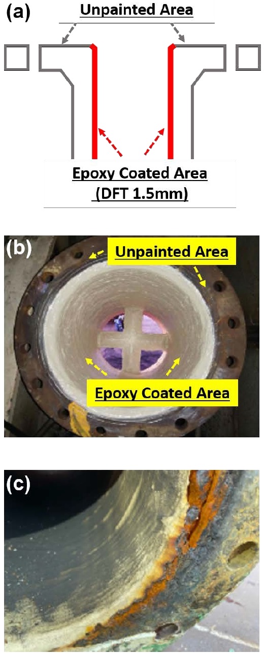
The general coating area and the general appearance are schematically displayed in Figures 1(a) and (b), respectively. The inside coating was only painted up to the weld area and not on the flange surface. This coating procedure was applied because there is no standard procedure for flange surface coating, and when the flanges are painted, the risk of seawater leakage through the gasket between the flanges increases.

(a) Schematic of overboard pipe, (b) top view of flange surface with the unpainted area, and (c) corroded pipe
For ships with a corroded or destroyed distance piece, the flange surface was not painted uniformly, and it was confirmed by visual inspection that corrosion progresses at the boundary between the flange and the end of the inner tube coating and flange. In addition, a common characteristic of ships with corrosion failure at the distance piece was that there was no painting on the entire surface. This is because there was no standard procedure for flange surface coating when installing pipes at the repair shipyard, and the coatings were arbitrarily removed from the flange surface to avoid leakage through the gasket. Therefore, it was confirmed that the flange surface was not protected by the coating coming into contact with seawater, and corrosion first started at the painted end and the uncoated flange surface, as shown in Figure 1(c).
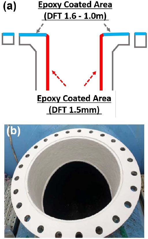
This is an improvement to the pipe corrosion problem. The pipe flange surface was fully painted by an improved coating procedure to prevent pipe corrosion, as shown in Figures 2(a) and (b). In addition, an appropriate coating procedure was developed and shared with repair shipyards to prevent the recurrence of the problem of uncoating on the flange surface. There was no pipe corrosion problem for two years after implementing the improvement plan.

(a) Improved coating procedure for overboard pipe flange and (b) improved full coating on overboard pipe flange surface
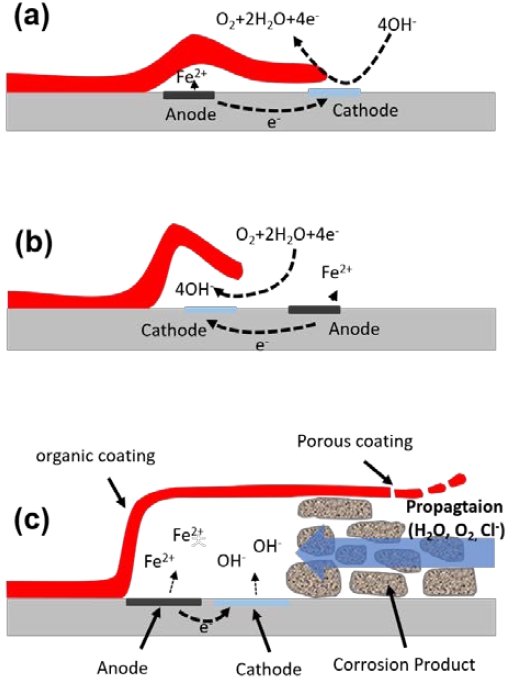
Figure 3 shows the corrosion process on the flanges. Corrosion is initiated at the end of the organic coating on the flanges and is accelerated by sulfuric acid and chlorides, as shown in Figures 3(a) and (b), as well as carbon dioxide, which enhances acidification at the corrosion site [8]. The corrosive cell structure under organic coating, shown in Figure 3(c), consists of an active anodic site and an inactive tail saturated with corrosion products. The oxygen and chloride ions diffuse into the exfoliated spaces under the organic coating. Thus, a corrosion cell is established between an acidified anode at the head of the peeling progress and an alkaline cathode at the tail of the peeling process, saturated with water and oxygen, whereas oxygen is reduced at the head of the filling.
4. Conclusion
In this paper, we have reported a recent flange coating method for preventing corrosion-induced pipe failure. To prevent pipe corrosion of the EGCS overboard pipe, the painting material should be selected based on its corrosion resistance to prevent acidic leakage. In addition, before painting, it should be coated with a sufficient coating thickness, including appropriate surface treatment. Since the common feature of corrosion-induced pipe failure is the presence of an uncoated area, causing a mismatch between the gasket and flanges, the unpainted areas contribute significantly to pipe corrosion failure. Therefore, the application of the fully coated surface described herein can prevent corrosion-induced pipe failure.
Author Contributions
Conceptualization, I. Y. Park; Methodology, I. Y. Park; Formal Analysis, I. Y. Park; Investigation, I. Y. Park; Resources, I. Y. Park; Data Curation I. Y. Park and Y. W. Kim; Writing-Original Draft Preparation, I. Y. Park; Writing-Review & Editing, Y. W. Kim and J. H. Yang; Visualization, Y. W. Kim; Supervision, J. H. Yang.
References
-
K. Capaldo, J. J. Corbett, P. Kasibhatla, P. Fischbeck, and S. N. Pandis, “Effects of ship emissions on sulphur cycling and radiative climate forcing over the ocean,” Nature, vol. 400, pp. 743-746, 1999.
[https://doi.org/10.1038/23438]

- B. Beherends and G. Liebezeit, Reducing SO2 and NOX emissions from ships by a seawater scrubber, BP Marine Report, Germany, 2003.
-
A. Andreasen and S. Mayer, “Use of seawater scrubbing for SO2 removal from marine engine exhaust gas,” Energy & Fuel, vol. 21, no. 6, pp. 3274-3279, 2007.
[https://doi.org/10.1021/ef700359w]

- L. Osipova, E. Georgeff, and B. Comer, Global scrubber washwater discharges under IMO’s 2020 fuel sulfur limit, The International Council on Clean Transportation, ICCT Report, United States, 2021.
- ClassNK, Corrosion of distance piece on SOx scrubber discharge water line, TEC-1205, NIPPON KAIJI KYOKAI (ClassNK), Japan, 2020.
-
I. Park, J. Noh, Y. Yun, and J. Yang, “A study on corrosion of distance piece on exhaust gas cleaning system (EGCS) discharge water line,” Journal of Advanced Marine Engineering and Technology, vol. 44, no. 6, pp. 453-456, 2020.
[https://doi.org/10.5916/jamet.2020.44.6.453]

-
J. Teuchies, T. J. S. Cox, K. V. Itterbeeck, F. J. R. Meysman, and R. Blust, “The impact of scrubber discharge on the water quality in estuaries and ports,” Environmental Sciences Europe, vol. 32, no. 103, 2020.
[https://doi.org/10.1186/s12302-020-00380-z]

-
S. D. Cramer and B. S. Covino, Jr., Corrosion: Fundamentals, Testing, and Protection, ASM Handbook, vol. 13A, ASM international, United States, 2003.
[https://doi.org/10.31399/asm.hb.v13a.9781627081825]


