Methods for designing and evaluating the structural stability of a diamond wire cutting saw by computational analysis
Copyright © The Korean Society of Marine Engineering
This is an Open Access article distributed under the terms of the Creative Commons Attribution Non-Commercial License (http://creativecommons.org/licenses/by-nc/3.0), which permits unrestricted non-commercial use, distribution, and reproduction in any medium, provided the original work is properly cited.
Abstract
The necessity of decommissioning offshore plants is becoming increasingly important because of aging. Therefore, a proper selection of decommissioning equipment and evaluation of the structural stability is necessary for the efficiency and safety of decommissioning work. In this research, methods for designing and evaluating the structural stability of a diamond wire cutting saw (DWS), which is one of the major equipment in decommissioning offshore plants, are introduced. Parametric analyses are performed to appropriately design and evaluate the structural stability. Consequently, stress decreased significantly (from 195.5 MPa to 112.3 MPa in the cutter part and from 168.2 to 110.1 MPa in the arm part) and weight increased minimally (3% in the cutter part and 0.1% in the arm part) from the initial design. Notably, the DWS is considered that appropriate design was performed by selecting proper design variables, design values that satisfied the allowable stress, and minimizing the weight increase.
Keywords:
Offshore plant decommissioning, Decommissioning equipment, Parametric analysis, Structural analysis, Structural stability, Computational analysis1. Introduction
Offshore plants have been installed since the 1920s, and approximately 7,600 fixed offshore platforms have been installed by 2015. Offshore plants consist of various equipment and structures that are exposed to the sea environment and have their own lifespan. The fixed platform has a lifespan of approximately 30 years, and 50% of pre-installed platforms have almost reached the end of their lifespan [1][2].
Offshore plant decommissioning involves the removal of some or all of the platform and equipment from the site when the profitability of the oil well is low or their lifespan reaches the end. Decommissioning objects are mainly fixed platforms, pipelines, and subsea machines. The decommissioning equipment used for cutting and lifting varies from objects and work [3][4]. In this research, a diamond wire cutting saw (DWS), which is one of the major decommissioning equipment, is considered as the research subject among various decommissioning equipment.
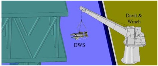
The DWS and decommissioning situations are shown in Figure 1. The davit and winch move the DWS, and the DWS cuts the pipelines of the platforms. In this research, methods for designing and evaluating the structural stability of the DWS by parametric analysis are introduced to design properly and minimize the weight increase.
2. Methods for Designing and Evaluating the Structural Stability of DWS
2.1 Evaluation of the Initial Design
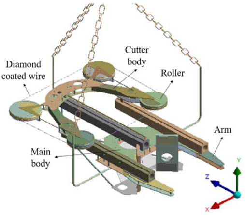
The DWS is the equipment for cutting pipelines or the structure of platforms by rotating the diamond-coated wire, as shown in Figure 2. It is common to have arms that can clamp the body for stable cutting work. The DWS has not been localized; therefore, a design review through the initial design and simulation is necessary for localization.
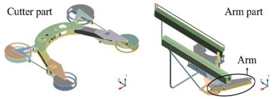
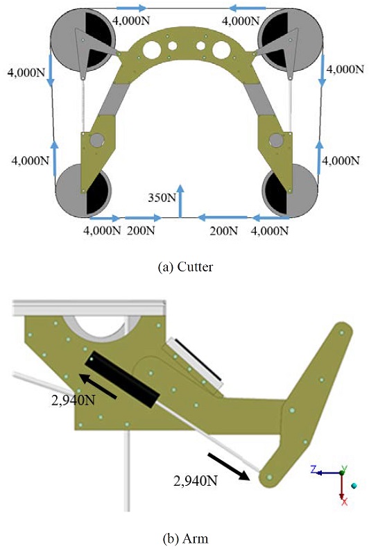
In general, a principal load is applied to the arm and cutter. Therefore, the design of these two parts should be evaluated. The wire tension and feeding force should be considered for the cutter part. The clamping load must be considered to the arm part.
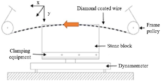
Additional loads, such as the current velocity and hydrostatic pressure, can be considered if needed. The values of each load are selected from related test results [5]-[9]. The wire tension and cutting force from the test results according to the test shown in Figure 4 are listed in Table 1. The maximum load for each load type is applied to the parts in contact with the wire. The clamping load based on the test results is applied according to the clamping direction (Figure 5).
In the cutter, the simply supported condition is applied to the parts in contact with the rails as boundary conditions. In the arm, the x and z directions of the surfaces in contact with the pipe are limited, and the y direction of the surfaces in contact with the chain is limited.
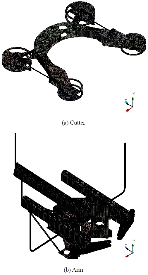
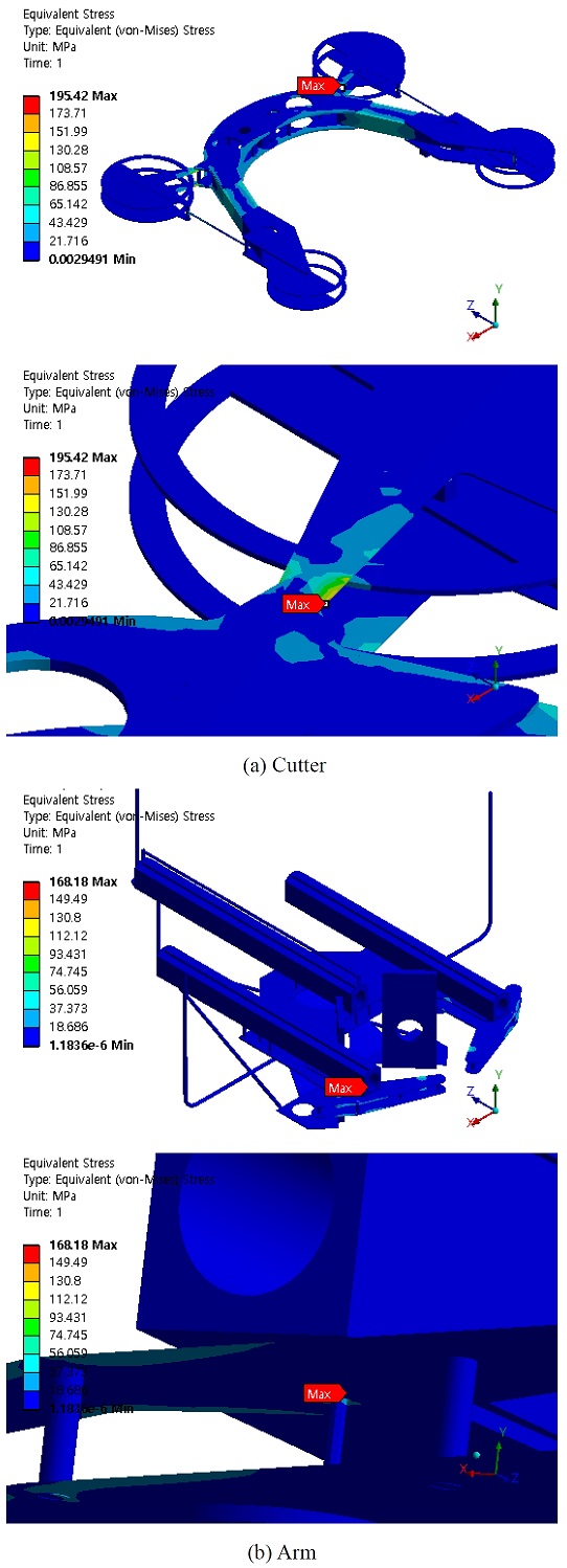
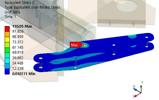
Al6061 is used as the material for the DWS, and the allowable stress is considered (Table 2). The current velocity (0.54 m/s) at the target location (Attaka field, Indonesia) is also applied from the front. Figure 6 shows the generated mesh, and mesh information is shown in Table 3. A mesh of size 4–15 mm is used in the cutter analysis and that of 4–10 mm in the arm analysis. Figure 7 shows the analysis results of the initial design. In the cutter part, a high stress was observed at the connecting part of the roller connecting plate because of the wire tension and cutting force. In the arm part, a high stress was observed at the arm plate and the hinge bar. Based on the parts that showed high stress, we attempt to set design variables to satisfy the structural stability and minimize the weight increase.
2.2 Parametric Analysis by Design Variables
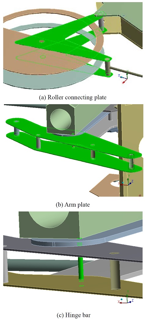
Figure 8 and Table 4 show the selected design variables. In the cutter part, one design variable is selected because only the roller connecting plates showed critical structural stability. In the arm part, two design variables are selected because the arm plate and hinge bar have an effect on each other.
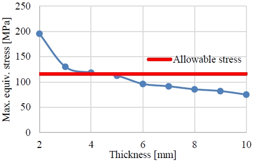
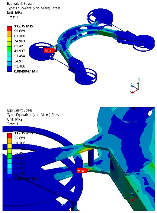
Figure 9 shows the parametric analysis results of the cutter part. As the thickness increased, max. stress decreased. And if the thickness was more than 4 mm, the gradient of the line showed no steep change. To select the proper thickness, determining the point near and lower than the allowable stress is reasonable for considering the structural stability and minimizing the weight increase. Consequently, a thickness of 5 mm was selected as the final design, and stress analysis results are shown in Figure 10.
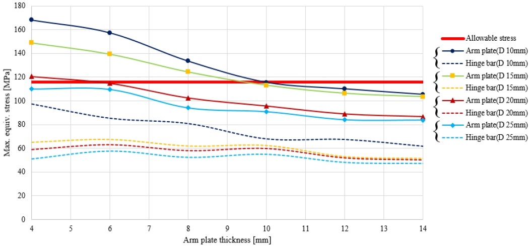
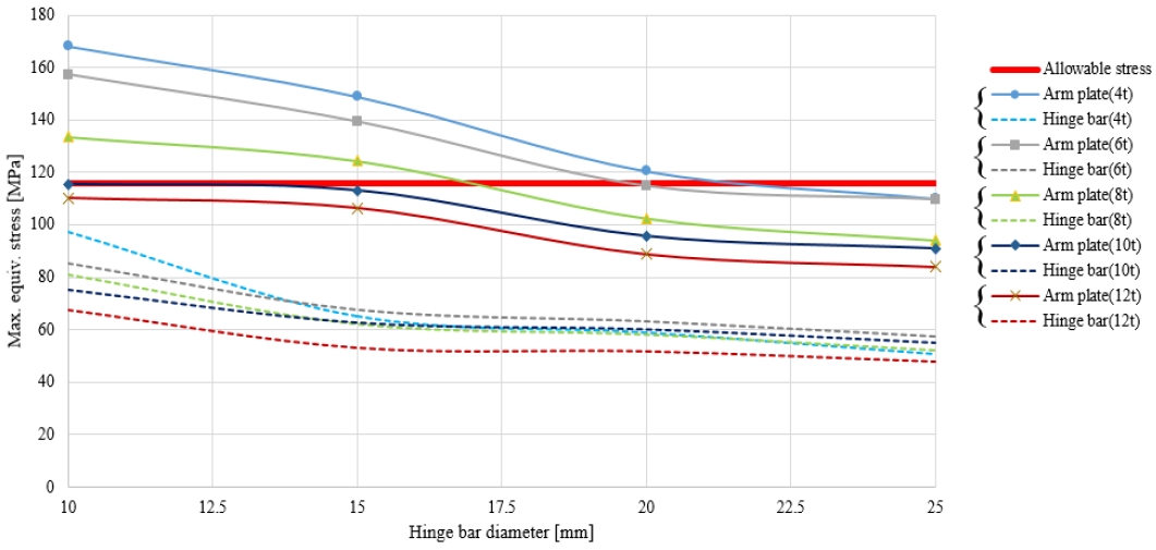
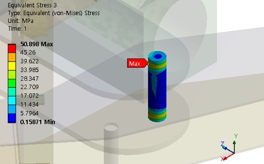
In the case of the arm part, parametric analyses considering two design variables are performed. Figures 11 and 12 show the results of the parametric analysis. As the thickness of the arm plate and the diameter of the hinge bar increased, max. stress decreased. As the thickness and diameter increased, the gradient of the lines gradually increased. Based on the graphs, three candidates that are near and lower than the allowable stress are selected (Table 5). The volume of each candidate is calculated to determine the lighter design among the three candidates. As a result, candidate 1 was selected as the final design because it had the smallest volume. However, the selection of the design point for the final design may vary from each designer. The allowable design range, preference of the designer, defined standard of components, and design limitations exist. Therefore, selecting the design condition in advance and considering it properly are necessary for the designer. Figures 13 and 14 show the stress analysis results of the final arm part design. The max. stress of the arm plate and hinge bar was lower than the allowable stress and minimized weight increase.
3. Conclusion
In this study, methods for designing and evaluating the structural stability of a DWS are introduced. Proper load conditions are selected by considering the test results. Parametric analyses are performed to properly design and evaluate the structural stability. As shown in Table 6, the final design satisfied the allowable stress (116 MPa) and minimized the weight increase (3% in the cutter part and 0.1% in the arm part) from the initial design. In related studies on parametric analysis, the selection of parameters for the model, structural analysis per parameter, and selection of the optimized value considering the design stress were performed [10]. Similar methods were also used in this study, and proper values were obtained from the parametric analysis. Even though the target model is not a DWS, this method can be applied to any other equipment to design and evaluate the structural stability. The graphs of the stress analysis results from the parametric analysis can be useful when designing. In addition, design values drawn from the analysis can be retained as back data and can be reused when redesigning and evaluating the equipment without much effort. There are further plans to acquire data such as the ship behavior, wind load, and lifting load from the target location (Attaka field, Indonesia) and evaluate considering the actual decommissioning situation.
Acknowledgments
This research was a part of the project titled ‘Development of eco-friendly decommissioning and commercialization technology for offshore plants’, funded by the Ministry of Oceans and Fisheries, Korea. (Project No. 20210655)
Author Contributions
Conceptualization, H. U. Kim and J. H. Lee; Formal Analysis, H. U. Kim; Validation, H. U. Kim and J. H. Lee; Resources, H. U. Kim and J. H. Lee; Writing—Original Draft Preparation, H. U. Kim; Writing—Review & Editing, H. U. Kim and J. H. Lee.
References
- M. Y. Kwak, A Study on Decommissioning and Reutilization of Abandoned Offshore Facilities, Master Thesis, Division of Marine System Engineering, Korea Maritime & Ocean University, Republic of Korea, 2018 (in Korean).
-
N. A. Zawawi, M. S. Liew, and K. L. Na, “Decommissioning of offshore platform: A sustainable framework,” 2012 IEEE Colloquium on Humanities, Science & Engineering Research, pp. 26-31, 2012.
[https://doi.org/10.1109/CHUSER.2012.6504275]

- B. W. Nam, and et al., Development of Basic Technologies for Decommissioning Process of Offshore Platform, Technical Report TRKO201800014313, Ocean System Safety Research Division, KRISO, Republic of Korea, 2017 (in Korean).
- C. S. Jeon, “A study on the decommissioning of oil and gas platform,” Journal of the Korean Society of Industry Convergence, vol. 23, pp. 1081-1091, 2020 (in Korean).
-
M. S. Yang, S. I. Kim, J. R. Cho, and H. J. Jo, “Development of underwater cutting device for the dismantling of offshore plant steel structures,” Journal of the Korean Society of Marine Engineering, vol. 43, no. 7, pp. 522-527, 2019 (in Korean).
[https://doi.org/10.5916/jkosme.2019.43.7.522]

-
S. Turchetta, L. Sorrentino, and C. Bellini, “A method to optimize the diamond wire cutting process,” Diamond and Related Materials, vol. 71, pp. 90-97. 2017.
[https://doi.org/10.1016/j.diamond.2016.11.016]

- G. Tantussi, M. Lanzetta, S. Gentile, and G. Depperu, “Diamond wire cutting: Failure modes, risks for safety and workers’ protection,” Second International Congress Dimension Stones (ICDS) XXI Century challenges, pp. 193-198, 2008.
-
L. Cao, Q. Meng, L. Wang, and W. Tong, “Research on underwater diamond wire saw,” 2006 International Conference on Mechatronics and Automation, pp. 1695-1700, 2006.
[https://doi.org/10.1109/ICMA.2006.257452]

-
Z. Wang, B. Zhang, L. Q. Wang, and D. Xu, “Research on experimentation of diamond wire saw cutting compound pipes underwater,” Material Science Forum, vol. 626-627, pp. 303-308, 2009.
[https://doi.org/10.4028/www.scientific.net/MSF.626-627.303]

-
H. Ye, and et al., “Optimal design of a three tape-spring hinge deployable space structure using an experimentally validated physics-based model,” Structural and Multidisciplinary Optimization, vol. 56, pp. 973-989, 2017.
[https://doi.org/10.1007/s00158-017-1810-5]


