A magnetic energy harvesting device using current transformer
Copyright © The Korean Society of Marine Engineering
This is an Open Access article distributed under the terms of the Creative Commons Attribution Non-Commercial License (http://creativecommons.org/licenses/by-nc/3.0), which permits unrestricted non-commercial use, distribution, and reproduction in any medium, provided the original work is properly cited.
Abstract
Magnetic energy harvesting technology for non-contact self-generative IoT sensors using power line networks have been actively studied. However, the proposed methods are designed to operate at a large current for high-voltage transmission line applications. Therefore, in this study, a device was developed to harvest magnetic energy at a low current. The basic characteristics of energy harvesting of commercial current transformers (CTs) were reviewed, and a method was proposed to enhance the harvested AC power. A peak AC power of 2.7 W was harvested from a copper wire carrying a current of 7 Arms using five CTs in series connection. The practicality of the proposed device was demonstrated by operating a high-brightness LED with the DC power converted in the rectifier circuit.
Keywords:
Energy harvesting, Magnetic energy, Magnetic core, Current transformer, Rectifier1. Introduction
The method of supplying power to a wireless sensor for Internet of Things (IoT) has become increasingly popular. Various energy harvesting methods have been proposed with the increase in the number of wireless sensor devices connected to the Internet for networking. Generally, IoT devices are common types of sensors and they are used for data collection, analysis, and data transfer to servers or the cloud for storage. Although, the manufacturing of compact batteries has significantly advanced, it can ensure operation only for a limited time. Furthermore, management of numerous batteries will be required with an increase in number of devices, and exhausted batteries will have to be identified and replaced individually. Therefore, a method is required that can harvest and supply energy from the surrounding environment. Light, vibration, pressure, or temperature difference might be considered as sources of power harvesting without physical interaction. Randall [1] demonstrated that solar technology can be utilized in indoor lighting environments. Lee et al. [2] demonstrated that vibrational energy can be used to generate power (up to 830 μW) by moving magnets through coils and springs in resonant structures.
Stordeur and Stark [3] developed a thermoelectric device capable of producing 15 mW of power at 10 temperature differences. Leland et al. [4] implemented a cantilever-mounted piezoelectric bimorph and NdFeB (neodymium iron boron alloy) permanent magnet that coupled the magnetic field of the cable to a conducting alternating current. They were able to generate a power of 208 μW and 345 μW using cables carrying 9.4 A and 13 A current, respectively. However, the power generated by these devices is insufficient for IoT devices that have a high-power consumption.
Recently, magnetic energy harvesting techniques using power lines have attracted considerable attention to obtain high output, and it has been proposed for self-contained operation of power line peripheral devices. B. Park et al. [5] proposed an optimal design for a toroidal core magnetic energy harvester considering magnetic saturation, and demonstrated that an induced voltage of 60.9 V can be obtained with a power line current of 60 A at 380 V and 60 Hz. This is a suitable method for high voltage lines such as power transmission lines. However, a strong magnetic field generated by a large current can saturate the magnetic core and result in a magnetic permeability close to zero. Conversely, R. M. White et al. [6] proposed a small energy harvester based on coils and flux guides to supply power to atmospheric sensors and radios attached to a single conductor of an existing overhead distribution line. It was demonstrated that an AC output power of 22.8 mW was achieved with an 800 Ω load resistance when the conductor current was 10 Arms. However, it had a low output power and it required a credit-card-sized rectangular coil with 1250 turns of insulated copper wire.
In this study, a commercial current transformer (CT) was used as a magnetic energy harvesting device. A typical energy coupler consists of an insulating conductor wounded (100 turns or greater) on a cylindrical magnetic core with a high magnetic permeability. However, commercial CTs have a simple structure with approximately 10 windings and they are readily available. It was demonstrated that several watts of AC power can be harvested from the magnetic field of distribution lines carrying an alternating current of 10 A or less.
2. Principle of Magnetic Energy Harvesting of Current Transformer
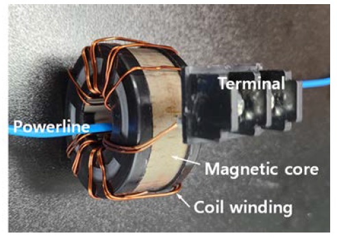
Figure 1 shows the photograph of a commercial current transformer (CT) with a current ratio of 60/5 A. It is designed to convert a large current (of up to 60 A) into a low current (of 5 A or less) for measurement. The magnetic core had a cylindrical shape wound with a silicon steel plate, and an inner diameter (ra) of 23 mm, an outer diameter (rb) of 52 mm, and a height of 24 mm. Since the saturation magnetic flux density of silicon steel is greater than 2.0 T, it is advantageous for magnetic energy harvesting than ferrite (0.4 T) or nano-crystalline alloy (1.2 T). The effective magnetic path length (leff) and cross-sectional area (Aeff) were calculated to be 118 mm and 348 mm2, respectively. An insulated copper wire with a diameter of 1 mm was wound 10 times on a magnetic core as a secondary winding.
According to Faraday's law of electromagnetic induction, a time-varying current in a power line generates an alternating magnetic field around the wire. The generated magnetic field induces an AC voltage at the coil terminal, and the output voltage can be converted into a DC voltage through a rectifier circuit.
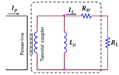
Figure 2 shows the equivalent circuit of a CT in which the magnetic field of the coil core is not saturated. The voltage induced in the coil by the change in magnetic flux acting at a distance r from the center of a long conductor carrying alternating current is given by Equation (1).
| (1) |
where μ, ω, N, and Ip are the permeability of the core, AC frequency, turns of the secondary side of the CT, and rms current in the power-line conductor, respectively.
The AC power harvested from the load resistance is given by Equation (2) [6].
| (2) |
where Lμ and Rw are the inductance and resistance of the coil, respectively. When the frequency ω is set to 60 Hz, the maximum AC power delivered to the load is calculated by Equation (3) [6].
| (3) |
where RL for maximum power transfer is given by
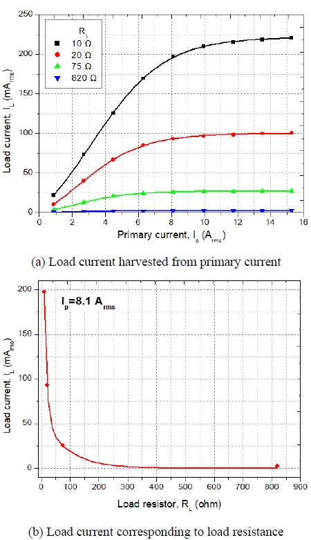
When the primary side current was 16 A, a corresponding secondary side current was induced as shown in Figure 3. The load current became saturated when the primary current was greater than 7 Arms, because the magnetic core was saturated by the large current at the primary side. When the primary current was set at 8.1 A, the current corresponding to the load resistance exhibited an exponential relationship as shown in Figure 3(b).
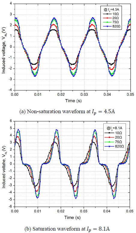
The voltage waveform measured when the core was saturated was comparatively analyzed. The core did not saturate at Ip = 4.5 A. Therefore, the output waveform obtained was a sine wave as shown in Figure 4(a). The core was saturated at Ip =8.1 A, and it formed a distorted output waveform as shown in Figure 4(b). The transmission window of the output waveform and the effective time of the voltage output were reduced. It can be observed from Equation (1) that the load voltage proportionally increased with respect to the primary current. However, after the saturation of the core, the load current did not increase and remained constant. Therefore, this was the optimum condition for maximum power harvesting.
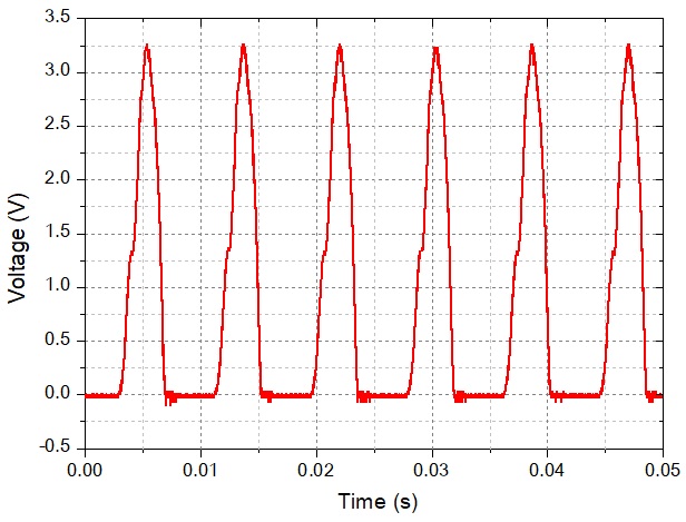
Considering a voltage waveform with a load resistance of 75Ω in Figure 4(b), the saturation current is 25 mArms and the peak voltage is 4.5V. However, as shown in Figure 5, when a full-wave rectification was performed, the peak voltage dropped corresponding to the forward diode voltage. This occurred because the DC bias voltage required to drive the sensors was insufficient. Therefore, an energy harvesting device that can be connected to several CTs was proposed to solve this problem.
3. Experiment and Results
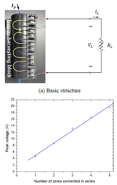
To harvest watt-class AC power, CTs were connected in series as shown in Figure 6(a). The peak voltage increased linearly in proportion to the number of CTs as shown in Figure 6 (b).
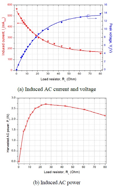
The output characteristics corresponding to the load resistance are shown in Figure 7(a). The load voltage and load current exhibited an opposite response with respect to the change in load resistance. The reason is the limitation of the power harvested due to the physical limitations of the energy harvesting device. The peak AC power obtained was 2.7 W when the load resistance was approximately 20 Ω as shown in Figure 7(b).
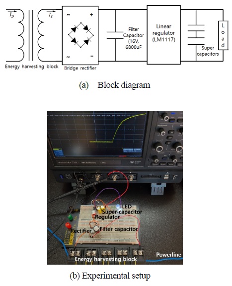
A schematic diagram for converting the AC output of the energy harvesting device to DC output is shown in Figure 8(a). A core coil and a filter capacitor (16 V, 68000 μF) were connected to the input and output terminals of the bridge rectifier, respectively. A constant voltage regulator implemented by LM1117 was used for stable DC voltage output, and a battery was connected to the output terminal. Two supercapacitors (10 F, 3.8 V) were connected in series connection as a battery for storing the harvested energy. The circuit configured for the charging experiment is shown in Figure 8(b). A high-brightness white LED (HB10P-White, Yinhui Photoelectronic) with a forward current of 20 mA was connected as a load.
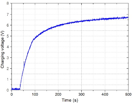
Figure 9 shows the charging profile of the super-capacitor as a function of time when a primary current of 7 Arms flowed through the power cable. The charging voltage increased rapidly during the first 60 seconds. The initial current was approximately 550 mArms. However, it gradually decreased as charging proceeded. Subsequently, when the current reached 450 mArms and remained constant, the supercapacitor was completely charged. In this experiment, we were able to drive up to two high-brightness LEDs. At a constant supply of a primary current of 7 Arms, the supercapacitor maintained a DC output voltage of 7 V while operating the two LEDs at maximum luminous intensity (3800 mcd). The DC power consumed to operate the two LEDs was estimated to be 280 mW. If the size and weight of the energy harvesting block is not an issue, the CT can be added to increase the harvesting power. The battery capacity can also be appropriately selected according to the power consumption of the load.
4. Conclusion
A study was conducted to harvest the electrical energy from the magnetic field of an AC power line using a commercial CT. Various experiments were performed using a single 60/5A CT for energy harvesting. A series-connected CT block was suitable as an energy harvesting device for self-powered electronic devices to replace batteries. Since the number of CTs and the output voltage are linearly proportional, it is possible to design a customized energy harvesting device that adjusts the number of CTs according to the power consumption required by the load. A peak AC power of 2.7 W was harvested using a primary current of 7 amps with five CTs connected in series. The proposed device is suitable for IoT sensors that can harvest energy from a current-carrying conductor without a physical connection.
Acknowledgments
This research was supported by through the development of local specialized industries of Ministry of SMEs and Startups (S2965908).
Author Contributions
Conceptualization, K. Sohn and H. Kim; Methodology, K. Sohn and H. Kim; Software, K. Sohn; Validation, K. Sohn and H. Kim; Formal Analysis, K. Sohn; Investigation, K. Sohn and H. Kim; Resources, K. Sohn and H. Kim; Data Curation, K. Sohn; Writing—Original Draft Preparation, K. Sohn; Writing—Review & Editing, K. Sohn and H. Kim; Visualization, K. Sohn; Supervision, K. Sohn; Project Administration, K. Sohn and H. Kim; Funding Acquisition, K. Sohn and H. Kim.
References
- J. F. Randall, On Ambient Energy Sources for Powering Indoor Electronic Devices, PhD dissertation, Ecole Polytech. Fed. de Lausanne, Lausanne, Switzerland, 2003.
- J. M. H. Lee, S. C. L. Yuen, W. J. Li and P. H. W. Leong, "Development of an AA size energy transducer with micro resonators," 2003 IEEE International Symposium on Circuits and Systems , p. IV, 2003.
- M. Stordeur and I. Stark, "Low power thermoelectric generator-self-sufficient energy supply for micro systems," Proceedings ICT'97. 16th International Conference on Thermoelectrics, pp. 575-577, 1997.
- E. S. Leland, R. M. White, and P. K. Wright, “Energy scavenging power sources for household electrical monitoring,” The Sixth International Workshop on Micro and Nanotechnology for Power Generation and Energy Conversion Applications, pp. 165-168, 2006.
-
B. Park, D. Kim, J. Park, K. Kim, J. Koo, H. Park, and S. Ahn, “Optimization design of toroidal core for magnetic energy harvesting near power line by considering saturation effect,” AIP Advances, vol. 8, no. 5, 056728, 2018.
[https://doi.org/10.1063/1.5007772]

-
R. M. White, D.-S. Nguyen, Z. Wu, and P. K. Wright, “Atmospheric sensors and energy harvesters on overhead power lines,” Sensors, vol. 18, no. 2, p. 114, 2018.
[https://doi.org/10.3390/s18010114]

-
J. Moon and S. B. Leeb, “Analysis model for magnetic energy harvesters,” in IEEE Transactions on Power Electronics, vol. 30, no. 8, pp. 4302-4311, 2015.
[https://doi.org/10.1109/TPEL.2014.2357448]


