Implantable ascites drainage stent designs and experiments to improve the quality of life in terminal cancer patients
 ; Hyeokjun Kwon2
 ; Bong-Soo Park3
 ; Si-Hyung Park4
 ; Jin-Han Park5
 ; Cheol-Kyu Oh6
 ; Ye-Jin Kim7
 ; Il-Hwan Kim†
 ; Junghyuk Ko††
Copyright © The Korean Society of Marine Engineering
This is an Open Access article distributed under the terms of the Creative Commons Attribution Non-Commercial License (http://creativecommons.org/licenses/by-nc/3.0), which permits unrestricted non-commercial use, distribution, and reproduction in any medium, provided the original work is properly cited.
Abstract
Ascites are determined in the terminal stages of cancer and liver cirrhosis patients. Ascites cause inconvenient symptoms; therefore, drainage is required. The conventional drainage method requires a considerable amount of time for patients to drain the proper quantity of ascites. However, the required time for treatment is too long for patients diagnosed with ascites, because they do not have a long time to live from when they are diagnosed. Considering that diagnosed patients want to spend their time with acquaintances, a new ascites drain method needs to be developed to improve the quality of life of patients. Therefore, we designed two new implantable drainage stents, and designed experimental instruments and designs to test the performance of the stents. The experiments were designed with two considerations: i) A stent is required to move to the abdominal cavity when the abdominal pressure is higher than the abdominal cavity, and ii) A stent is required to prevent urine from moving from the bladder to the abdominal cavity. Presumably, this is the first attempt, and we are sure that the improved stent can improve the quality of life of cancer patients.
Keywords:
Ascites, Drainage, Implantable, Quality of life, Stent1. Introduction
The general awareness of cancer treatment until the late twentieth century was that cancer is incurable, except at an early stage; however, as the recent trend of survival rates and mortality [1]-[3] of cancer patients with long-term treatment has indicated, recent improvements in medical technology have suggested positive prospects for cancer treatment [4]-[7]. However, the positive prospect and high mortality rate of terminal cancer patients in stage IV is still complex.
The terminal state of patients with cancer suffers from diverse symptoms. One of those symptoms, especially in gastrointestinal cancers such as stomach, colorectal, and pancreas, is ascites of the peritoneal cavity that occupying ten percent of the entire as cites [8]. In addition, inconveniences from peritoneal cavity distension and nausea, dyspepsia, pain, and orthopnea with the increasing pressure of the peritoneal cavity caused by ascites [9] decreases the quality of life of patients [10]. Commonly utilized methods to alleviate ascites include diet control, utilization of a diuretic, and large-volume paracentesis, [11] among paracentesis is considered an effective method [12] for this purpose, owing to the simple procedure [13]-[14]. However, various complications, such as bleeding, infection, and bowel perforation, can occur.
The time to take the treatment was not fixed, and varied from 30 min to 24 h [15]-[16]. Patients who undergo paracentesis treatment spend a considerable amount of time from an hour to a day, if the time required to go to the hospital is considered. The time to take paracentesis is relatively long if the survival time of the patient is not very long, approximately 20 weeks from the time of diagnosis [17]-[18].
Patients who prepare for death evaluate that sharing good emotional communication and time is essential to prepare for death among various attributes [19]. In this prospect, a novel and more comfortable method needs to be developed into a more time-savable method because current methods take significant amount of time, and it is not a good method if patients who undergo paracentesis want to save more time to share with people around them.
Solbach et al. [20] researched another conventional type of “paracentesis catheter implantation” and positive effects on paracentesis frequency and time, even though they drained a similar quantity of ascites. The research also indicates that an implantable paracentesis system can provide a new experience that can conduct paracentesis anywhere if they have proper devices. However, we want to determine another method or device to deliver ascites outside the patient, such as the continuous delivery of ascites to the urinary bladder. One alternative device was “Alfapump” (Sequana Medical NV), which delivers ascites using the pigtail and pump. Stirnimann et al. [21] and Fotopoulou et al. [22] researched a novel type of drainage, by utilizing “Alfapump,” continuous low-flow drainage through the urinary bladder, and found positive effects on paracentesis frequency and flow rate by reducing paracentesis frequency and quantity of drained ascites. However, these devices require electrical circuits and regular battery charging. In addition, it can break down, and the patient may bear the inconvenience of inserting an instrument into the body. We discovered the main idea of a permanently implantable catheter that can deliver ascites directly into the bladder. We believe that this idea can play a significant role in time-efficient paracentesis.
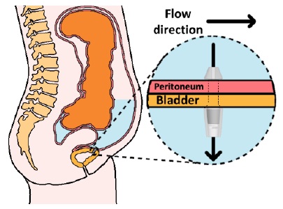
According to that need, we devised one of the novel drain methods, “Implantable ascites drainage stent,” as illustrated in Figure 1. Abdominal pressure increases if ascites is caused. In this situation, the stent that we devised will emit ascites into the bladder directly, the closest organ responsible for waste discharge, utilizing pressure differences. More specifically, after implantation of the stent into the bladder wall between the peritoneal cavity and bladder, ascites are moved into the bladder by pressure differences if the pressure of the peritoneal cavity increases, and the patient excretes waste, including ascites and urine.
In this study, we designed two types of implantable stents, and confirmed the performance of the stent utilizing an instrumental experiment that had a similar construct to the peritoneal cavity and bladder.
2. Method
2.1 Instrumental experiment set-up
Design the peritoneal cavity -bladder connecting implantable stent for ascites emitting, utilizing pressure difference. The conditions that need to be considered in stent design are as follows:
Condition #1: Allow movement of ascites in the peritoneal cavity has higher pressure than bladder pressure.
Condition #2: Not allow movement of ascites when the peritoneal cavity has a smaller pressure than the bladder pressure.
-Condition #3: Fulfill a size to allow insertion of the stent that will be slotted with a urethral tube.
Two design proposals were expected to fulfill these conditions, and they comprised of first and second designs.
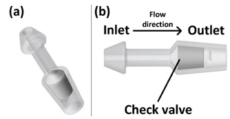
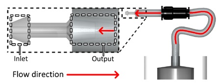
As illustrated in Figure 2, stent 1 was designed with a focus on the utilization of check valves. The stent has a narrow neck, stubby head, and tail to fix in the bladder wall, as illustrated in Figure 1. The head (inlet) will be placed toward the peritoneal cavity, and the tail (outlet) will be placed toward the bladder. In condition #1, the check valve retreats, and allows ascites to flow into the bladder. In condition #2, the check valve blocks the path of the stent, and does not allow ascites flow. In this way, the stent controls the flow of ascites from the peritoneal cavity into the bladder.
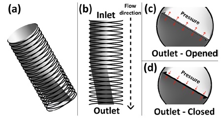
Stent 2 was designed with a focus on the utilization of a stent and narrow outlet, which opens and closes the outlet, and is controlled by the pressure around the outlet, as illustrated in Figure 3. In condition #1, as illustrated in c of Figure 3, the force of flow allows the narrow outlet to be opened because the pressure of the inlet is higher than that of the outlet. In condition #2, as illustrated in Figure 3(d), the pressure around the narrow outlet closes the outlet, because the pressure at the outlet is higher than that at the inlet. Furthermore, the two stents meet compatibility with urethra tube sizes (condition #3), with 8.7 mm or more and a “French catheter scale (Fr)” of 26 Fr or more.
Experimental instruments designed to test stent performance. Considerations of instrument design are as follows:
Condition #4: Control relative pressure with flow-rate control
Condition #5: Stent storable structure to test the stent with changing relative pressure.
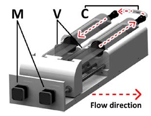
We have devised an experimental instrument and design that meets the conditions, and has the following configurations. As illustrated in Figure 4, the stepper motors were utilized to control the volume in the syringe by moving the plunger forward and backward. Two syringe pump settings were prepared, each of which was responsible for the inlet and outlet. Stents were slotted into the center of the tube, which was connected to each syringe. Relative pressure control was conducted as follows: based on the equation that the product of pressure and volume is constant, pumps control pressure by controlling the volume of each syringe.
2.2 Experiment condition set up
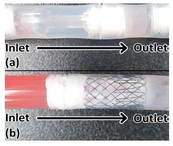
The flow rates of the experiments were 20, 60, and 100 mL/h. The bladder pressure (outlet pressure) and peritoneal cavity pressure (inlet pressure) were 20, 50, and 100 (mmH2O). “Forward’ flow direction,” as presented in Table 1, means it flows from inlet to outlet. “Backflow” of flow direction means it flows from outlet to inlet, and is an unintended flow direction in design. These “directions” are not actual flow directions, but predicted directions. While the stents were tested, they were slotted in a tube, as illustrated in Figure 5.
As illustrated in Figure 6, we experimented to verify whether the flow can be restrained or not when it is received in backflow, without a relative pressure difference by connecting the output of the stents and the syringe pump. The flow rate was set at 100mL/h and operated for approximately an hour, as an experimental condition.
3. Experimental Results
3.1 Relative pressure base performance experiments
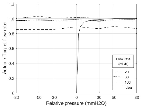
As presented in Table 2, the average flow rates were 17.51, 58.68, and 101.03, when the flow rates were 20, 60, and 100. Regarding forwarding direction flow, stents allowed flow from the peritoneal cavity to the bladder under most conditions, i.e., under positive relative pressure conditions. However, the smaller the flow rate, the lower the actual flow quantity per target flow quantity.
As presented in Table 2, the average flow rates were 17.38, 58.71, and 101.45 when the flow rates were 20, 60, and 100. Regarding backflow, stents allowed flow from the peritoneal cavity to the bladder under most conditions, i.e., under zero or negative relative pressure conditions. However, similar to the forward direction, the smaller the flow rate, the lower the actual flow quantity per target flow quantity.
3.2 Backflow restrain ability experiment
As presented in Table 3, based on the fact that stents allow a backflow, the backflow restrain function was not activated. When syringe pumps move flow through the output of stents with 100mL/h of flow rate, stent 1 allows flow at 101.7 of flow rate, and stent 2 allows flow at 101.6 of flow rate.
4. Discussion and Conclusion
The main purpose of these stents was to allow flow when the peritoneal cavity has a higher pressure than the bladder, instead of the opposing cases. In addition, the actual experimental results need to be illustrated as an ideal plot in Figure 7. However, most of the results indicate that both stents allow flow, even if the bladder has a higher pressure. These results indicate that the designed stent can control forward direction flow, but not the opposing case, and additional improvements will be needed to supplement the experimental conditions. In addition, a transparent thin membrane was coated outside the stent structure, in the case of stent 2. This membrane was a very vulnerable structure for force and pressure, and the membrane was damaged when slotting the stent for the experiment or allowing pressure, and it was expected to be the main reason for the experimental failure of backflow control.
Nevertheless, the main idea that implantable ascites drainage instruments, which can reduce treatment time and increase the convenience of users, is still a valid and challenging question. Therefore, the idea can be realized if we experiment with more sophisticated stents and experimental instruments. Therefore, we will conduct additional experiments to validate the idea with a sophisticated setup, such as an improved stent and experimental instrument.
In this study, we designed two types of implantable stents, and confirmed the performance of stents with an exclusive experimental instrument to confirm the feasibility of the newly revised ascites drainage method, which is considered as a time-efficient method, compared to current methods. Accordingly, the main idea of the implantable ascites drain instrument is still challenging; however, experiments suggest that the design of the stent and experimental setup need to be improved to validate the novel type of ascites drainage instrument. Therefore, we plan to conduct additional research to compensate for the lack of this experiment, and to validate the idea of “implantable ascites drainage stent.”
Acknowledgments
This work was supported by the National Research Foundation of Korea (NRF) grant funded by the Korea government (MSIT) (No.2017R1C1B5076247).
Author Contributions
Conceptualization, H. Kim, I. -H. Kim, and J. Ko; Methodology, H. Kim and H. Kwon; Software, H. Kim; Validation, H. Kim, H. Kwon, B. -S. Park, S. -H. Park, J. -H. Park, Cheol-Kyu Oh, Y. -J. Kim, and J. Ko; Formal Analysis, H. Kim; Investigation, H. Kwon; Resources, H. Kim; Data Curation, H. Kim; Writing—Original Draft Preparation, H. Kim and H. Kwon; Writing—Review & Editing, B. -S. Park, S. -H. Park, J. -H. Park, Cheol-Kyu Oh, Y. -J. Kim, I. -H. Kim, and J. Ko; Visualization, H. Kim; Supervision, I. -H. Kim and J. Ko; Project Administration, I. -H. Kim and J. Ko; Funding Acquisition, I. -H. Kim.
References
-
A. Dubecz, I. Gall, N. Solymosi, M. Schweigert, J. H. Peters, M. Feith, and H. J. Stein, “Temporal trends in long-term survival and cure rates in esophageal cancer: A SEER database analysis,” Journal of Thoracic Oncology, vol. 7, no. 2, pp. 443-447, 2012.
[https://doi.org/10.1097/JTO.0b013e3182397751]

-
M. Amiri, F. Janssen, and A. E. Kunst, “The decline in stomach cancer mortality: exploration of future trends in seven European countries,” European Journal of Epidemiology, vol. 26, no. 1, pp. 23-28, 2011.
[https://doi.org/10.1007/s10654-010-9522-9]

-
M. Malvezzi, P. Bertuccio, F. Levi, C. La Vecchia, and E. Negri, “European cancer mortality predictions for the year 2012,” Annals of Oncology, vol. 23, no. 4, pp. 1044-1052, 2012.
[https://doi.org/10.1093/annonc/mds024]

-
R. Baskar, K. A. Lee, R. Yeo, and K.-W. Yeoh, “Cancer and radiation therapy: Current advances and future directions,” International Journal of Medical Sciences, vol. 9, no. 3, pp. 193-199, 2012.
[https://doi.org/10.7150/ijms.3635]

-
D. Hanahan and R. A. Weinberg, “Hallmarks of cancer: The next generation,” Cell, vol. 144, no. 5, pp. 646-674, 2011.
[https://doi.org/10.1016/j.cell.2011.02.013]

-
L. A. Pollack, J. H. Rowland, C. Crammer, and M. Stefanek, “Introduction: Charting the landscape of cancer survivors’ health-related outcomes and care,” Cancer, vol. 115, no. S18, pp. 4265-4269, 2009.
[https://doi.org/10.1002/cncr.24579]

-
C. Pucci, C. Martinelli, and G. Ciofani, “Innovative approaches for cancer treatment: Current perspectives and new challenges,” eCancermedicalscience, vol. 13, pp. 961, 2019.
[https://doi.org/10.3332/ecancer.2019.961]

-
S. L. Parsons, S. A. Watson, and R. J. C. Steele, “Malignant ascites,” British Journal of Surgery, vol. 83, no. 1, pp. 6-14, 1996.
[https://doi.org/10.1002/bjs.1800830104]

-
E. Kipps, D. S. P. Tan, and S. B. Kaye, “Meeting the challenge of ascites in ovarian cancer: New avenues for therapy and research,” Nature Reviews Cancer, vol. 13, no. 4, pp. 273-282, 2013.
[https://doi.org/10.1038/nrc3432]

-
C. Kietpeerakool, S. Rattanakanokchai, N. Jampathong, J. Srisomboon, and P. Lumbiganon, “Management of drainage for malignant ascites in gynaecological cancer,” The Cochrane Database of Systematic Reviews, no. 12, 2019.
[https://doi.org/10.1002/14651858.CD007794.pub3]

-
M. Stukan, “Drainage of malignant ascites: Patient selection and perspectives,” Cancer Management and Research, vol. 9, pp. 115-130, 2017.
[https://doi.org/10.2147/CMAR.S100210]

-
C. P. Amendola, L. Romagnolo, and R. L. C. Araujo, Malignant Ascites in Critically Ill Cancer Patients, Oncologic Critical Care, Springer International Publishing, 2020.
[https://doi.org/10.1007/978-3-319-74588-6_73]

-
N. G. Peter, L. R. Clark, and J. R. Jaeger, “Fitz-Hugh-Curtis syndrome: A diagnosis to consider in women with right upper quadrant pain,” Cleveland Clinic Journal of Medicine, vol. 71, no. 3, pp. 233-241, 2004.
[https://doi.org/10.3949/ccjm.71.3.233]

-
E. M. Smith and G. C. Jayson, “The current and future management of malignant ascites,” Clinical Oncology, vol. 15, no. 2, pp. 59-72, 2003.
[https://doi.org/10.1053/clon.2002.0135]

-
W. H. Gotlieb, B. Feldman, O. Feldman-Moran, N. Zmira, D. Kreizer, Y. Segal, E. Elran, and G. Ben-Brauch, “Intraperitoneal pressures and clinical parameters of total paracentesis for palliation of symptomatic ascites in ovarian cancer,” Gynecologic Oncology, vol. 71, no. 3, pp. 381-385, 1998.
[https://doi.org/10.1006/gyno.1998.5215]

-
P. Appelqvist, J. Silvo, L. Salmela, and S. Kostiainen, “On the treatment and prognosis of malignant ascites: Is the survival time determined when the abdominal paracentesis is needed?” Journal of Surgical Oncology, vol. 20, no. 4, pp. 238-242, 1982.
[https://doi.org/10.1002/jso.2930200411]

-
R. N. Garrison, W. H. Kaelin, L. S. Heuser, R. H. Galloway, “Malignant ascites: Clinical and experimental observations.,” Annals of Surgery, vol. 203, no. 6, pp. 644-651, 1986.
[https://doi.org/10.1097/00000658-198606000-00009]

-
G. L. Jackson and N. M. Blosser, “Intracavitary chromic phosphate (32p) colloidal suspension therapy,” Cancer, vol. 48, no. 12, pp. 2596-2598, 1981.
[https://doi.org/10.1002/1097-0142(19811215)48:12<2596::AID-CNCR2820481210>3.0.CO;2-J]

-
A. Bovero, F. Gottardo, R. Botto, C. Tosi, M. Selvatico, and R. Torta, “Definition of a good death, attitudes toward death, and feelings of interconnectedness among people taking care of terminally ill patients with cancer: An exploratory study,” American Journal of Hospice and Palliative Medicine®, vol. 37, no. 5, pp. 343-349, 2020.
[https://doi.org/10.1177/1049909119883835]

-
P. Solbach, C. Höner zu Siederdissen, R. Taubert, S. Ziegert, K. Port, K., A. Schneider, K. Hueper, M. P. Manns, H. Wedemeyer, and E. Jaeckel, “Home-based drainage of refractory ascites by a permanent-tunneled peritoneal catheter can safely replace large-volume paracentesis,” European Journal of Gastroenterology & Hepatology, vol. 29, no. 5, pp. 539-546, 2017.
[https://doi.org/10.1097/MEG.0000000000000837]

-
G. Stirnimann, T. Berg, L. Spahr, S. Zeuzem, S. McPherson, F. Lammert, F. Storni, V. Banz, J. Babatz, V. Vargas, A. Geier, A. Stallmach, C. Engelmann, C. Trepte, J. Capel, and A. De Gottardi, “Treatment of refractory ascites with an automated low-flow ascites pump in patients with cirrhosis,” Alimentary Pharmacology & Therapeutics, vol. 46, no. 10, pp. 981-991, 2017.
[https://doi.org/10.1111/apt.14331]

-
C. Fotopoulou, T. Berg, A. Hausen, R. Hennig, R. Jalan, M. Malagó, J. Capel, A. De Gottardi, and G. Stirnimann, “Continuous low flow ascites drainage through the urinary bladder via the Alfapump system in palliative patients with malignant ascites,” BMC Palliative Care, vol. 18, p. 109, 2019.
[https://doi.org/10.1186/s12904-019-0497-3]

