Fatigue analysis of a hydraulic accumulator under severe working conditions
 ; Quang Dao Vuong2
 ; Van Chien Pham3
 ; Antony John Nyongesa4, 5
 ; Min-Ho Park5, 6
 ; Kitae Park7
 ; Won-Ju Lee5, †
Copyright © The Korean Society of Marine Engineering
This is an Open Access article distributed under the terms of the Creative Commons Attribution Non-Commercial License (http://creativecommons.org/licenses/by-nc/3.0), which permits unrestricted non-commercial use, distribution, and reproduction in any medium, provided the original work is properly cited.
Abstract
A hydraulic accumulator is a key component that absorbs the shock and vibrations of a hydraulic system of a marine diesel engine and controls the volume change according to the pressure change of the hydraulic oil. During the operation of a hydraulic accumulator, repeated concentrated stress is applied to the lowermost thread of the lower shell. The purpose of this study is to numerically investigate the structural safety and fatigue life for hydraulic accumulators under extreme pressure conditions. Structural and fatigue analysis were performed using finite element modeling under the operating conditions and test conditions of 30MPa and 40MPa pressure, respectively. As a result of the structural analysis, the maximum von Mises stress did not exceed the tensile strength under the operating conditions, whereas the von Mises stress of 1029 MPa under the test conditions exceeded the tensile strength: thus, the structural stability was not secured. The fatigue life was calculated using fatigue analysis with a design life of 106. Further, fatigue failure occurred within a short duration as it represented 160 cycles.
Keywords:
Fatigue analysis, Finite element modeling, Hydraulic accumulator, Lowermost thread, Structural analysis1. Introduction
The hydraulic accumulators in ships are installed in the engine hydraulic cylinder unit that operates the engine fuel injection and exhaust system, and functions to alleviate the high-pressure shock and pulsation generated during engine operation. A marine hydraulic accumulator is a key component of a marine engine that maintains constant pressure in the engine system and dampens the vibrations to ensure smooth engine operation. As the existing mechanical engine changes to an electronically controlled engine when a problem occurs in the control unit, the hydraulic accumulator for a ship compensates for the appropriate flow rate and pressure to prevent damage to the components of the hydraulic cylinder unit and to facilitate the smooth circulation during machine operation.
The hydraulic accumulator for ships consists of a hemispherical upper shell, a lower shell, a diaphragm, and a ring in contact with the upper shell and fastened to the lower shell. Marine hydraulic accumulators are operated under extreme pressure pulsations. If the pressure pulsation in the engine is abnormally severe due to a mechanical failure of the engine or an abnormality in the control system, and a continuous abnormal pressure pulsation occurs, the stress amplitude of the hydraulic accumulator becomes especially large; hence, the fatigue life is sharply reduced, and damage occurs. In this study, the hydraulic accumulator consists of a threaded hemispherical lower shell and a threaded ring, and an upper shell in contact with the ring. The lowermost threads of the lower shell are subjected to repeated concentrated stress during operation which can lead to deformation and damage to the hydraulic accumulators and cause accidents. Noh et al. [1] evaluated the fatigue life using thread-root radii of 0.1, 0.2, and 0.4 mm, and set the design criteria for the lower shell of the hydraulic accumulator subjected to the concentrated stress.
If damage occurs to the hydraulic accumulator of a ship, the normal function of the engine becomes impossible; therefore, the engine cylinder must be stopped and further maintenance carried out. When introducing autonomous and unmanned ships, it is necessary to optimize the structure to maintain continuous durability even under extreme pressure pulsation conditions and to operate normally at peak pressure, considering a situation in which there may be a minimum to no crew members capable of maintenance. The mechanical components can be destroyed in several ways.
The surface crack of a structure can gradually grow when subjected to millions of small cyclic load which can further cause a decrease in the strength and rapid failure of the material [2]. In this regard, various studies on the fatigue analysis of pressure vessels for ships have been conducted [3]-[6]. As a result of testing, the actual model exhibited fatigue failure under the test pressure conditions. Structural and fatigue analyses were performed using the ANSYS workbench under the test pressure conditions. Moreover, the areas subjected to concentrated stress were identified.
2. Finite Element Modeling
2.1 Model Background
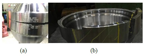
In the previous model, the shape was designed to relieve the stress concentration at the edge of the upper shell, which was the most vulnerable during structural and fatigue analyses, with a maximum stress of 822.11 MPa due to the pressure concentration, which was approximately 90% of the tensile strength of 880 MPa. However, in the improved model, the maximum stress occurred near the bottom thread, and the fatigue failure occurred in the area under the test pressure condition, as shown in Figure 1 (a). Figure 1 (b) shows the cross section of the accumulator owing to fatigue failure. In this study, fatigue analysis results were derived and reviewed for a model in which fatigue failure occurred.
2.2 Physical Geometry and Material Properties
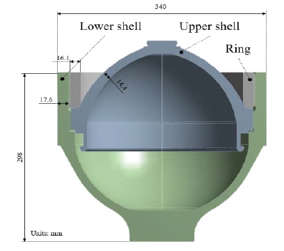
The hydraulic accumulator for ships is shown in Figure 2, it can be divided into upper shell, lower shell, and ring. A diaphragm is not considered in this study. The material of the accumulator is SCM440, and the basic properties of the material are shown in Table 1.
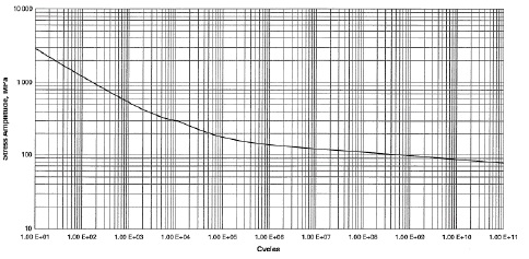
Fatigue failure is a structural damage induced by cyclic loading characterized by its occurrence at a stress lower than the yield stress of the material. The S-N curve is a schematic illustration that determines the correlation between the load and the number of repetitions until the specimen breaks by producing a test piece with the same material as the structural material and applying a repeated load to the test piece. In this study, as an alternative to performing a specimen test, data from ASME BPVC, Sec. VIIII, Div. 2 [7] was used. The S-N curve for the fatigue analysis is shown in Figure 3.
An axisymmetric model was considered in the analysis as the accumulator has an axisymmetric structure. In the case of the symmetric model in ANSYS workbench, the same result as the actual analysis result can be obtained with only 1/2 or 1/4 of the entire model, which is quite effective in reducing the analysis time.
2.3 Contact Condition
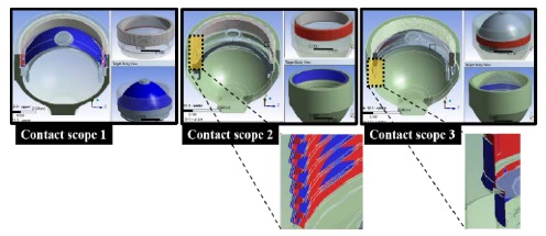
The contact conditions of the model are the upper shell and ring, the lower shell and ring, and the upper and lower shells. Contact is a circumstance in which two parts exhibits various modes, such as sliding or separation. In finite element analysis, the two regions show relative behavior in various contact modes, and the boundary conditions and shapes change accordingly. Therefore, contact analysis is a nonlinear analysis in which the boundary condition is changed due to the applied load. The two objects in contact interact and transmit loads. In finite element analysis, a contact area is preset for contact, and whenever deformation occurs due to a change in the load, contact is determined. Figure 4 demonstrates the contact scope of the accumulator. The frictional condition was set such that the contact surface could be separated in the normal direction and if the equivalent shear stress at the contact surface exceeds a certain magnitude, the objects in contact may slide relative to each other. When sliding (relative motion) of the two contact pairs occurs, a frictional force is generated, which causes shear stress and, consequently, shear deformation. The coefficient of friction is 0.3, which considers the actual accumulator assembly form.
2.4 Mesh Generation
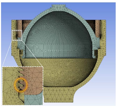
The proximity and curvature were used as the size functions of the mesh in the analysis. The accumulator was divided into 213,162 elements and 396,938 nodes and the refinement function was utilized to create a denser mesh for the lowermost thread of the lower shell, where the stress is concentrated as illustrated in Figure 5.
2.5 Simulation Condition
In the accumulator, the working fluid flows into the assembled model, and an operating pressure of 28-30 MPa acts on the inner wall of the vessel in the normal direction. In this study, structural and fatigue analyses were performed for a test pressure of 40 MPa, as well as the operating pressure. The bottom surface of the accumulator was set as a fixed support.
3. Analysis and Discussion
3.1 Structural Analysis
It is necessary to properly transform the triaxial stress state to generate an equivalent stress. In general, tensile tests of materials are performed in the uniaxial direction, and the yield stress and tensile strength, which are the results of the test, are also values in the uniaxial direction; however, it is difficult to compare as the stress exists in a triaxial stress state. Therefore, it is convenient to define the equivalent stress to express the triaxial stress state and compare it with the uniaxial stress. The equivalent stress is also called the von Mises stress, and its expression as a principal stress state is shown in Equation (1). The distortion energy theory was used to calculate the stress. In this theory, the strain energy of a material is composed of volumetric strain energy and shear strain energy. The yield occurs when the shear strain of the material is equal to the shear strain energy of the same material in a simple tensile state. This theory is also called von Mises theory.
| (1) |
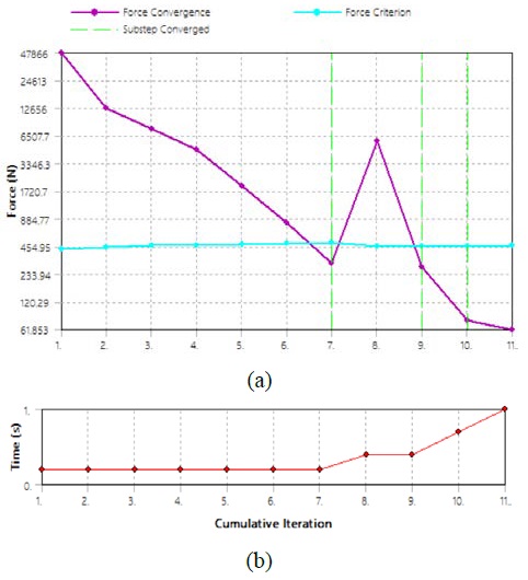
In nonlinear analysis, the stiffness matrix is not a constant but changes according to the value of the displacement vector, so the desired solution can be obtained through several calculations. The load acts on a step-by-step basis, dividing at each step into sub-steps and performing the analysis while incrementing the load in the order of the divided sub-loads. For the analysis of the sub-load, the slope (stiffness K) was repeatedly obtained, and the convergence was determined when the error was less than the force criterion. The Newton-Rapson method was used to obtain the slope. In Figure 6 (a), when the first-stage load is applied, it can be observed that the error or force convergence is less than the force criterion after seven stiffness gradients seven times. Subsequently, the sub-steps converged immediately after the 3rd and 4th loads were applied. Figure 6 (b) shows the convergence process in which four loads are sequentially applied and eleven cumulative iterations were performed [8].
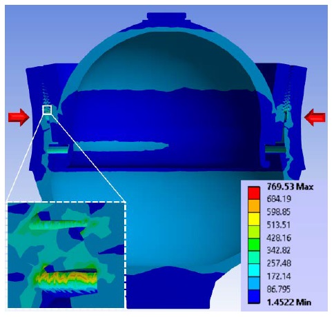
As shown in Figure 7, the outer surface of the threaded part of the lower shell was under compression, as depicted by the red arrow in Figure 7. Additionally, a von Mises stress of 769 MPa occurred near the lowermost thread, which does not exceed the tensile strength of 880 MPa; thus, it was concluded that the structural stability is secured under the operating conditions.
In contrast, when the pressure was 40 MPa, the maximum von Mises stress of the accumulator was computed as 1029 MPa, making it difficult to have structural stability.
3.2 Fatigue Analysis
A walled pressure vessel subjected to cyclic internal pressure represents a component subjected to mean tensile stress. The mean stress can have substantial influence on the fatigue behavior.
In fatigue life analysis, the S-N curve is widely used for life prediction, especially in high-cycle fatigue situations where the cyclic load is in the elastic region and the failure cycle is high. The S-N curve generated from the fully reversed loading type which is σm = 0 and R = −1 . The mean stress, σm and the stress ratio, R are given by Equation (2) and Equation (3).
| (2) |
| (3) |
Alternating stresses are usually lower than the yield strength of the material; however, the application of such alternating stresses can cause fatigue failure. To analyze fatigue failure, the Gerber method was utilized. The Gerber method, represented by Equation (4), is commonly used for ductile materials to predict the fatigue failure under a specific force or stress application.
| (4) |
In Equation (4), σalt is the absolute maximum value of the alternating stress, Sult is the ultimate tensile strength, and σm is the mean stress of the maximum and minimum peak points of the sinusoidal alternating stress.
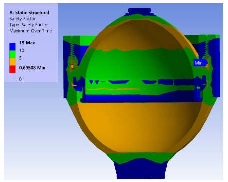
The safety factor is the ratio between the design allowable stress and the yield strength or the ultimate strength, which is the design criterion. If the design allowable stress is calculated using the safety factor and compared with the stress acting on the current structure, it is easy to verify the existence of any damage. When the von Mises discriminant is used, the safety factor is calculated by dividing the uniaxial yield strength of the material by the von Mises equivalent stress. The safety factor of the accumulator is shown in Figure 8.
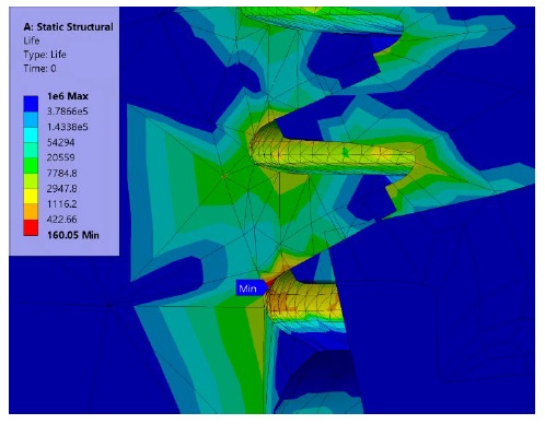
Similar to the structural analysis results and failure of the actual model, the fatigue analysis results also showed the lowest fatigue life near the lowermost thread of the lower shell. The results of the fatigue life are illustrated in Figure 9.
Figure 9 shows that a minimum of 160 cycles was found at the lowermost thread. As the design life is set to 106, the minimum lifespan is 160, and it has a low safety factor of 0.695, which model cannot withstand the fatigue life of 106 cycles.
4. Conclusion
Structural and fatigue analyses were performed under extreme conditions for a hydraulic accumulator to verify structural stability. Furthermore, the fatigue life estimation of a hydraulic accumulator was studied. The fatigue analysis was performed using the ANSYS workbench. The minimum cycle occurred at the lowermost thread of the lower shell, where the maximum equivalent alternating stress and fatigue damage was recorded. Significantly low fatigue life was estimated at the location subjected to repeated concentrated stress, and fatigue failure was observed at the same location in the actual model. Therefore, model improvements are required, such as, the reinforcement of the lowermost thread.
Acknowledgments
This research was supported by the Ministry of Science and ICT of Republic of Korea and National IT Industry Promotion Agency (S1226-21-1001).
Author Contributions
Conceptualization, D. -S. Kwon and W. -J. Lee; Methodology, D. -S. Kwon; Software, D. -S. Kwon; Validation, D. -S. Kwon, Q. -D. Vuong, V. -C. Pham, N. A. John, M. -H. Park and W. -J. Lee; Formal Analysis, D. -S. Kwon; Investigation, D. -S. Kwon; Resources, D. -S. Kwon; Data Curation, D. -S. Kwon Q. -D. Vuong and M. -H. Park; Writing—Original Draft Preparation, D. -S. Kwon; Writing—Review & Editing, Q. -D. Vuong, V. -C. Pham, K. Park and W. -J. Lee; Visualization, D. -S. Kwon; Supervision, W. -J. Lee; Project Administration, W. -J. Lee; Funding Acquisition, W. -J. Lee.
References
-
D. -H. Noh, J. -R. Cho, and J. -J. Kim, “Evaluation of the structural integrity and fatigue life of a hydraulic accumulator used for marine diesel engine according to the thread root radius,” Journal of Advanced Marine Engineering and Technology, vol. 44, no. 1, pp. 27-33, 2020.
[https://doi.org/10.5916/jamet.2020.44.1.27]

-
X. Chen and Y. Liu, “Finite element modeling and simulation with ANSYS workbench,” 2nd edition CRC Press, pp. 453-471, 2018.
[https://doi.org/10.1201/9781351045872]

- E.-U. Lee, “Fatigue analysis of pressure vessel regarding ASME Code,” Magazine and Journal of Korean Society of Steel Construction, vol. 8, no.1, pp. 32-38, 1996 (in Korean).
- J. -H. Kim and J. -H. An, “A study on the fatigue strength of compressed air tank for ships,” Journal of the Korean Society of Marine Engineering, vol. 29, no. 8, pp. 115-120, 2005 (in Korean).
- S. -I. Choi, Structure and fatigue analysis of high pressure vessel using finite element method, Master Thesis, Department of Mechanical Engineering, Kunsan University, Korea, 2017 (in Korean).
-
D. -Y. Kim, G. -H. Lee, and J. -W. Hur, “Life fatigue prediction of an accumulator composed of bladder and housing,” Journal of the Korean Society of Manufacturing Process Engineers, vol. 17, no. 5, pp. 58-63, 2018 (in Korean).
[https://doi.org/10.14775/ksmpe.2018.17.5.058]

- ASME, ASME Boiler and Pressure Vessel Code, Section VIII, Division 2 2017 Edition.
- J. -W. Choi, DIY in Mechanical Engineering, Seoul, Korea: Bogdoo Book Center, pp. 157-164, 2020 (in Korean).
