Application of JP-5 in a CRDI diesel engine with various fuel injection distribution strategy
Copyright © The Korean Society of Marine Engineering
This is an Open Access article distributed under the terms of the Creative Commons Attribution Non-Commercial License (http://creativecommons.org/licenses/by-nc/3.0), which permits unrestricted non-commercial use, distribution, and reproduction in any medium, provided the original work is properly cited.
Abstract
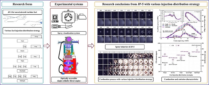
An experimental investigation was performed on an optically accessible single-cylinder common rail direct injection (CRDI) diesel engine and constant volume chamber (CVC) to analyze the spray behavior, and combustion and emission characteristics of jet propellant (JP -5) for naval aircrafts. It was demonstrated that JP-5 had a symmetrical spray pattern in the sac-type injector. Additionally, multiple pre-injections shortened the ignition delay of the main injection, and improved the engine performance and combustion efficiency. The production of CO emission significantly increased with an increase in the fuel injection distribution. Furthermore, multiple fuel injection caused an increase in HC emission under excessively advanced condition. The production of NOx pollutant was the lowest in the double strategy. However, it increased with an increase in the number of injections. The combustion visualization images demonstrated that the single injection strategy had a typical premixed combustion flame and the diffusion combustion flame of the main injection was detected in the multiple injection strategy.
Keywords:
Spray, Combustion, Emission, JP-5, Fuel injection distribution, Multiple injection1. Introduction
The most notable advantage of a diesel engine equipped with electronically controlled injectors and a common rail system is the diversification of fuel injection methods by controlling fuel injection timing, frequency, and pressure. In general, retardation of the fuel injection timing toward the top dead center (TDC) suppresses the rate of heat release (ROHR), resulting in reduction of nitrogen oxide (NOx) emission. In addition, the engine performance improves because the negative work is reduced in the compression stroke process. Lee [1] demonstrated that fuel injection distribution strategies such as multi-stage and split injection can enhance the engine performance and reduce harmful emissions such as NOx with the same fuel injection quantity compared with that of single injection strategies. In contrast to JP-8, which is used in land-based military aircraft, the kerosene-based jet propellant (JP-5) is used for naval aircraft turbine fuel. Bae et al. [2] highlighted that JP-8 as an alternative fuel for compression ignition diesel engines had a shorter spray tip penetration (STP), superior vaporization characteristic, and produced a homogeneous mixture inside the cylinder. A naval ship that carries naval aircrafts typically stores two types of fuels. The first type is a diesel fuel used for propulsion and power generation of naval vessels and the second type is JP-5, which is used in naval aircrafts. The physicochemical properties of JP-5 such as density, viscosity, and cetane number are inferior compared with that of diesel fuel. These characteristics prolong the ignition delay to ensure that the ROHR in the premixed combustion stage is rapidly increased. Cold flow plugging point (CFPP) of JP-5 is advantageous for an engine operating in an intense cold temperature environment. If a naval vessel storing diesel fuel and JP-5 were to perform a mission in an extremely low temperature field, using JP-5 as a single fuel might be a reasonable alternative. The utilization of JP-5 in a diesel engine equipped with a common rail system and electronically controlled injectors has not been extensively studied compared with that of JP-8. Therefore, to utilize JP-5 in diesel engines, various studies such as spray behavior, combustion and emission characteristics analysis are required.
Table 1 summarizes the review of the research results from the application of diesel engines and the diversification of injection methods with JP-5 and military aviation fuel. This study was conducted on an optically accessible common rail direct injection (CRDI) single-cylinder diesel engine and constant volume chamber (CVC) to analyze the spray behavior, combustion, and emission characteristics of JP-5. The fuel injection distribution strategy applied in this study was considered as a multiple injection strategy that combines pre-injection and main injection. The multiple injection strategies were divided into double, triple, quadruple and quintuple, and the experimental results were compared with that of the single injection strategy.
2. Experimental systems
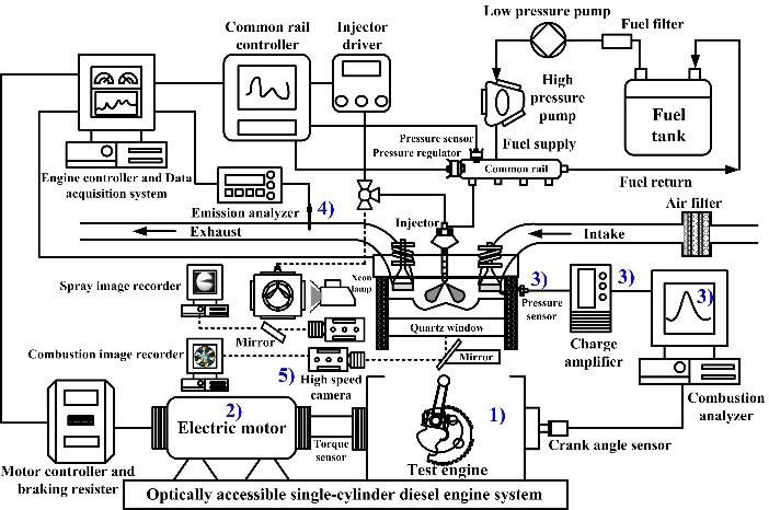
Figure 1 shows the schematic diagram of the test apparatus used to conduct this study. The experimental system consisted of the following main components:
- 1) An optically accessible CRDI single-cylinder diesel engine (Table 2).
- 2) A 22-kW electric motor (HV2 induction motor, Hyosung) that precisely controls the engine speed.
- 3) A combustion analyzer (MT-7000S, Mobiltek) including piezoelectric pressure sensors (Type 6056A, Kistler), and an amplifier (Type 5018 Kistler).
- 4) Sensor-based portable emission analyzer (Testo-350K, Testo)
- 5) High-speed camera (Fastcam SA3, Photron) for spray and combustion flame visualization.
The fuel was supplied to the test engine for spray behavior visualization. The torque generated by the engine was measured with a torque meter (T8 ECO rotary) coupled with the test engine and the electric motor.
3. Injection strategy and experimental conditions
The test fuel selected to conduct this study was JP-5, which is used naval aircrafts. The main physiochemical properties of the test fuel are summarized and compared with that of diesel fuel in Table 3.
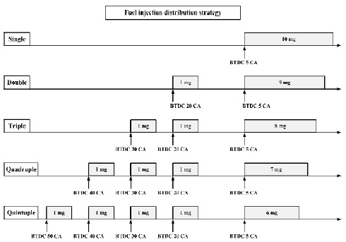
The fuel injection method is an important strategy that determines the performance and emission levels of diesel engine. In a diesel engine equipped with an electronically controlled injector, the fuel injection distribution strategy considered as multiple injection is an important parameter that affects the diesel engine performance and pollutant levels with the same amount of fuel. The fuel injection distribution strategy used in this study is multiple injection strategy, which is a combination of main injection and per-injection.
Figure 2 shows the concept of the fuel injection distribution strategy used in this study.
A high-performance optical lamp was selected to obtain a clear spray behavior image of JP-5. Detailed experimental conditions are shown in Table 4.
4. Results and discussions
4.1 Spray behavior characteristics
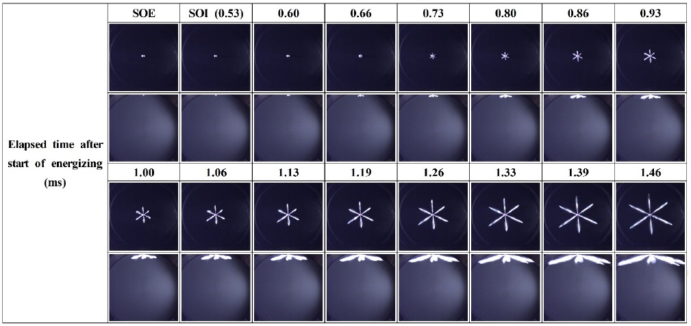
Figure 3 depicts the spray behavior of JP-5 using the high-speed camera in the CVC. The start of energizing (SOE) of the injector and the beginning of recording of the high-speed camera were synchronized to analyze the precise spray behavior. Fuel injection started at 0.53 ms after SOE and it showed a symmetrical characteristic as the spray developed. It has been reported to exhibit the characteristics of an asymmetrical spray pattern due to strong turbulence inside the nozzle when a jet fuel with low density, viscosity, and surface tension is used in a valve orifice covered (VOC) type injector. However, the sac-type injector is known to exhibit a symmetrical shape [14][15]. The spray droplets disperse with the development of the of JP-5 spray.
JP-5 has a lower density, viscosity, and distillation temperature as shown in Table 3. These properties of JP-5 lower the surface tension of the fuel, resulting in uncertainty inside the injector hole. It is hypothesized that the eddy current formed by uncertainty strengthens the spherical diffusion during spray development and results in a wider spray angle including a dispersion of spray droplets. In addition, the lower distillation temperature of JP-5 contributes to the excellent evaporation rate. The superior vaporization of JP-5 might disperse the spray and increase the mixing rate with ambient air [5][16].
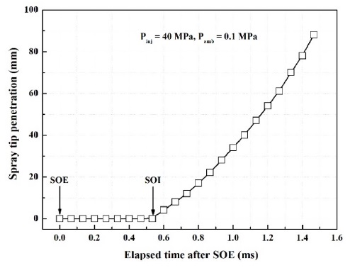
Figure 4 shows the results of STP based on images captured using a high-speed camera. The STP has a tendency to increase linearly with the development of the spray.
4.2 Combustion and emission characteristics
Figure 5 represents the effects of various fuel distribution strategies on in-cylinder pressure, ROHR, rate of pressure rise (ROPR), and P-V diagram.
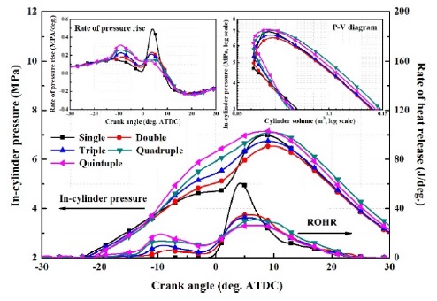
In-cylinder pressure, ROHR, ROPR, and P-V diagram characteristics with various fuel distribution strategy
It can be observed that the in-cylinder pressure, ROHR, and ROPR increase rapidly due to the strong premixed combustion intensity in the single injection strategy when only the main injection was applied. The in-cylinder pressure, ROHR, and ROPR rise gently in the multiple injection strategy as the fuel injection distribution was extended. Heat generation by a small amount of multiple pre-injection in the compression stroke process increased the in-cylinder pressure and temperature.
Therefore, the mixture formed before the main injection transformed into a richer mixture. The premixed rich mixture shortened the ignition delay of the main injection, suppressed the ROHR of the main injection, and lowered the premixed combustion intensity.
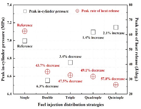
Figure 6 shows the peak in-cylinder pressure and ROHR. The peak ROHR decreased because the amount of fuel in the main injection decreased and ROHR was suppressed.
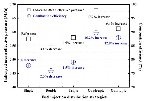
A significant reduction of ROHR (by 57.8%) was observed in the quintuple strategy compared with that of single injection mode. In the double and triple injection strategy, the peak in-cylinder pressure was decreased by 6.3% and 3.4%, respectively. The quadruple and quintuple strategies showed an increase in the peak in-cylinder pressure. This can be explained from result of the continuous combustion of the rich mixture formed by the multiple pre-injection. IMEP used as a representative factor of combustion quality is closely related to combustion efficiency, which is defined as the ratio of fuel chemical energy and actual heat release.
It can be observed in Figure 7 that the IMEP decreased by 3.1% in the double strategy. However, it increased from the triple strategy. It can be observed from the P-V diagram in Figure 5 that this is because the in-cylinder pressure slightly increased during the expansion stroke compared with that of the single injection strategy. Therefore, it can be concluded that the multiple injection strategy has a positive effect on the improvement of combustion efficiency.
Figure 8 shows the results that support this conclusion. An increase in the fuel injection distribution improved the fuel conversion efficiency, which is defined as the ratio of the fuel chemical energy and power, resulting in enhancement of engine performance.
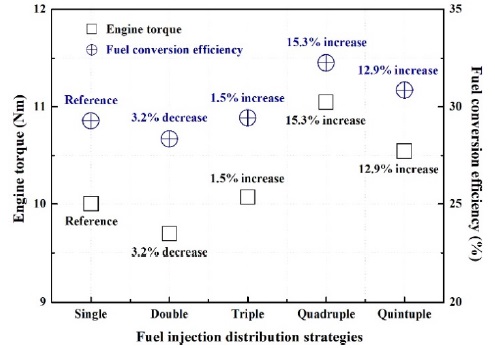
Engine torque and fuel conversion efficiency characteristics with various fuel distribution strategy
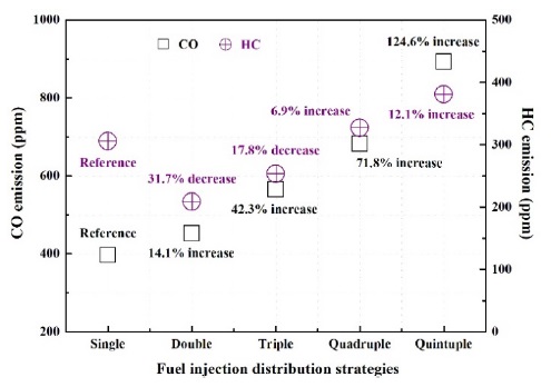
Figure 9 shows CO and HC emissions with the fuel injection distribution strategy. The heat released from the main injection decreased with an increase in the number of multiple pre-injections. In addition, low-temperature combustion such as incomplete combustion occurred resulting in lower CO oxidation rate. An increase in the number of pre-injections resulted in higher HC emission. A greater amount of HC was produced from the quadruple strategy than that of the single-injection strategy. Pre-injection improved the combustion quality of the main injection and reduced the amount of unburned HC. However, pre-injection in excessively advanced condition resulted in cylinder wall wetting and seeping of spray droplets into the crevice volume. These reasons were noted as a cause for increase in the unburned HC production.
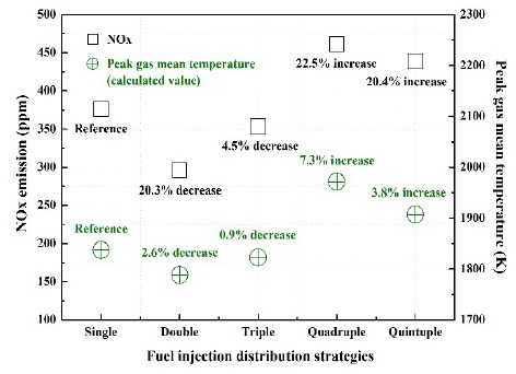
Figure 10 shows NOx and peak gas mean temperature (GMT) results with various fuel injection distribution conditions.
In general, NOx is considered as thermal NOx, which is formed in the region where the combustion gas temperature is high. The following formula was applied to calculate the combustion gas temperature [17][18].
| (1) |
| (2) |
| (3) |
Here, P(θ), V(θ), and T(θ) are the in-cylinder pressure, volume, and temperature at crank angle, respectively. mintake is the mass of air inside the cylinder at intake valve closing, ρair is the air density, VIVC is the cylinder volume at intake valve closing, vl is the function of valve lift, θvod,intake is the intake valve opening duration, θvod,exhaust is the exhaust valve opening duration, θIVO and θEVO are the intake valve opening angle and exhaust valve opening angle, respectively. Although the peak ROHR of the multiple injection strategy was lower than that of the single injection strategy, it can be confirmed that peak in-cylinder pressure was similar or higher with an increase in the number of injections. Continuous combustion by pre-injection extension in the multiple injection strategy resulted in higher in-cylinder pressure and temperature. The production of NOx was decreased by 20.3% in the double injection strategy and was increased by 22.5% in the quintuple injection strategy.
4.3 Combustion visualization
Figure 11 shows combustion process images with various fuel injection distribution conditions. The ignition delay of the single injection strategy was longer than that of the multiple strategy based on the luminosity of the flame. The combustion pattern of the single injection strategy was similar to that of a typical premixed combustion. The ignition delay of the main injection became shorter and the flame spread in the form of diffusion combustion with an increase in the number of pre-injections in the multiple injection strategy. The ROHR of the single injection strategy rapidly dropped after ATDC 6.5 CA compared with that of the multiple injection strategy, and it can be observed that the combustion flame disappeared quickly during the expansion stroke.
5. Conclusions
An experimental investigation was conducted to analyze the combustion and emission characteristics including spray behavior visualization by applying various injection distribution strategies on an optically accessible CRDI single-cylinder diesel engine and constant volume chamber. The following conclusions were obtained from the experimental results:
- 1) The sac-type injector had a symmetrical spray behavior. The lower distillation temperature of JP-5 resulted in a higher evaporation rate and dispersed the spray droplets. The superior vaporization characteristic of JP-5 enhanced the air-fuel mixture formation.
- 2) Multiple pre-injection shortened the ignition delay of the main injection and suppressed the ROHR. As the fuel injection distribution extended, the peak in-cylinder pressure and engine performance were increased. Combustion efficiency, which is defined as the ratio of fuel chemical energy and actual heat release, and fuel conversion efficiency calculated as the ratio of the fuel chemical energy, and power were improved compared with that of single injection strategy.
- 3) A significant production of CO was observed by low-temperature combustion and lower oxidation rate with multiple injection. Greater unburned HC pollutants were generated due to cylinder wall wetting and the seeping of spray droplets into the crevice volume under excessively advanced condition. The production of NOx was proportional to the peak combustion gas mean temperature. The amount of NOx produced was the lowest in the double strategy and it gradually increased with multiple injection.
- 4) It was confirmed from the luminosity combustion flame images that the ignition delay became shorter with an increase in the number of pre-injections. In the single injection strategy, a typical premixed combustion process by rapid ROHR was detected, and the combustion flame of the main injection exhibited a typical diffusion combustion process with a gently lasting ROHR in the multiple injection strategy.
Abbreviations
| CO : | Carbon monoxide |
| CVC : | Constant volume chamber |
| IMEP : | Indicated mean effective pressure |
| CFPP : | Cold flow plugging point |
| CRDI : | Common rail direct injection |
| GMT : | Gas mean temperature |
| HC : | Hydrocarbon |
| JP : | Jet propellant |
| NOx : | Nitrogen oxides |
| Pinj : | Injection pressure |
| ROHR : | Rate of heat release |
| ROPR : | Rate of pressure rise |
| SOE : | Start of energizing |
| SOI : | Start of injection |
| STP : | Spray tip penetration |
Acknowledgments
This study was supported by the 2021 Academic Research Project of the Naval Institute for Ocean Research of the Republic of Korea Naval Academy.
Author Contributions
This research presented in this paper was wholly contributed by the author.
References
-
H. Lee, “Effects of multiple uniformity split injection strategies on combustion and exhaust emissions characteristics in a single-cylinder diesel engine,” Journal of Advanced Marine Engineering and Technology, vol. 44, no. 2, pp. 117-125, 2020.
[https://doi.org/10.5916/jamet.2020.44.2.117]

-
C. Bae and J. Kim, “Alternative fuels for internal combustion engines,” Proceedings of the Combustion Institute, vol. 36, no. 3, pp. 3389-3413, 2017.
[https://doi.org/10.1016/j.proci.2016.09.009]

-
D. M. Korres, D. Karonis, E. Lois, M. B. Linck, and A. K. Gupta, “Aviation fuel JP-5 and biodiesel on a diesel engine,” Fuel, vol. 87, no. 1, pp. 70-78, 2008.
[https://doi.org/10.1016/j.fuel.2007.04.004]

-
K. Yehliu, A. L. Boehman, and O. Armas, “Emissions from different alternative diesel fuels operating with single and split fuel injection,” Fuel, vol. 89, no. 2, pp. 423-437, 2010.
[https://doi.org/10.1016/j.fuel.2009.08.025]

-
J. Lee and C. Bae, “Application of JP-8 in a heavy duty diesel engine,” Fuel, vol. 90, no. 5, pp. 1762-1770, 2011.
[https://doi.org/10.1016/j.fuel.2011.01.032]

-
J. Lee, H. Oh and C. Bae, “Combustion process of JP-8 and fossil diesel fuel in a heavy duty diesel engine using two-color thermometry,” Fuel, vol. 102, pp. 264-273, 2012.
[https://doi.org/10.1016/j.fuel.2012.07.029]

-
H. K. Suh, “Investigation of multiple injection strategies for the improvement of combustion and exhaust emissions characteristics in a low compression ratio (CR) engine,” Applied Energy, vol. 88, no. 12, pp. 5013-5019, 2011.
[https://doi.org/10.1016/j.apenergy.2011.06.048]

-
M. R. Herfatmanesh, P. L. Mohammadreza Anbari Attar, and H. Zhao, “Experimental investigation into the effects of two-stage injection on fuel injection quantity, combustion and emissions in a high-speed optical common rail diesel engine,” Fuel, vol. 109, pp. 137-147, 2013.
[https://doi.org/10.1016/j.fuel.2013.01.013]

-
K. Chug, A. Moiz, J. Johnson, S. -Y. Lee, C. B. Kweon, and A. Montanaro, “Spray-combustion interaction mechanism of multiple-injection under diesel engine conditions,” Proceedings of the Combustion Institute, vol. 35, no. 3, pp. 3061-3068, 2015.
[https://doi.org/10.1016/j.proci.2014.07.054]

-
J. Lee, J. Lee, S. Chu, H. Choi, and K. Min, “Emission reduction potential in a light-duty diesel engine fueled by JP-8,” Energy, vol. 89, pp. 92-99, 2015.
[https://doi.org/10.1016/j.energy.2015.07.060]

-
K. Mathivanan, J. K. Mallikarjuna, and A. Ramesh, “Influenece of multiple fuel injection strategies on performance and combustion characteristics of a diesel fueled HCCI-An experimental investigation,” Experimental Thermal and Fluid Science, vol. 77, pp. 337-346, 2016.
[https://doi.org/10.1016/j.expthermflusci.2016.05.010]

-
S. Park, H. J. Kim, D. H. Shin, and J. T. Lee, “Effects of various split injection strategies on combustion and emissions characteristics in a single-cylinder diesel engine,” Applied Thermal Engineering, vol. 140, pp. 422-431, 2018.
[https://doi.org/10.1016/j.applthermaleng.2018.05.025]

-
H. Park, C. Bae, and C. Ha, “A comprehensive analysis of multiple injection strategies for improving diesel combustion process under cold-start conditions,” Fuel, vol. 255, 2019.
[https://doi.org/10.1016/j.fuel.2019.115762]

-
L. Pickett and L. Hoogterp, “Fundamental spray and combustion measurements of JP-8 at diesel conditions,” SAE International Journal of Commercial Vehicles, vol. 1, no. 1, 2008.
[https://doi.org/10.4271/2008-01-1083]

-
C. Soteriou, R. Andrews, and M. Smith, “Direct injection diesel sprays and the effect of cavitation and hydraulic flip on atomization,” SAE Technical Paper, 950080, SAE International, USA, 1995.
[https://doi.org/10.4271/950080]

-
K. J. Myong, H. Suzuki, J. Sendra, and H. Fujimoto, “Spray inner structure of evaporating multi-component fuel,” Fuel, vol. 87, no. 2, pp. 202-210.
[https://doi.org/10.1016/j.fuel.2007.04.017]

-
N. Septivani and B. W. Riyandwita, “Spark ignition engine modeling for in-cylinder pressure and temperature prediction using Simulink,” MATEC Web of Conference, vol. 204, no. 04001, 2018.
[https://doi.org/10.1051/matecconf/201820404001]

-
R. K. Maurya, Reciprocating Engine Combustion Diagnostics, Switzerland: Springer, 2019.
[https://doi.org/10.1007/978-3-030-11954-6]


