Numerical study on lubrication performance and dimple effects in a journal bearing
Copyright © The Korean Society of Marine Engineering
This is an Open Access article distributed under the terms of the Creative Commons Attribution Non-Commercial License (http://creativecommons.org/licenses/by-nc/3.0), which permits unrestricted non-commercial use, distribution, and reproduction in any medium, provided the original work is properly cited.
Abstract
In this study, the lubrication performance and dimple effects in journal bearings were studied. Various parameters affecting the bearing lubrication, such as temperature, rotational speed, and eccentricity, were investigated. The obtained results indicated that when the eccentricity and rotational speed increased, and the lubricant temperature decreased, the pressure acting on the bearing increased. It is revealed that by introducing the dimple structure on the bearing surface, the lubrication performance is significantly more improved than that of the plain bearing. The dimple structure reduces the contact area between the shaft and bearing while maintaining the resultant force constant, and the volume fraction reduction prevents cavitation erosion inside the bearing.
Keywords:
Journal bearing, Dimple effect, Lubrication, Cavitation, Volume fraction1. Introduction
A bearing is a mechanical element that supports the rotation of the shaft, while supporting its load. The bearing types can be classified into rolling and sliding bearings. Rolling bearings support the rotation of the shaft, owing to the rolling contact, and support the load by introducing balls or rollers between the shafts and bearings. The sliding (or journal) bearings have a high-viscosity lubricant between the shafts and bearings. It is a mechanical element that supports the rotation of the shaft, and supports the load by lubrication. The sliding bearings have less friction, because the friction is solely related to the viscosity of the lubricant when the shaft has a proper number of rotations (rotating speed). Unlike rolling bearings with point or line contact, sliding bearings are adopted for high speed and loads because they have surface contact. However, owing to the high load and high eccentricity between the shaft and the center of the bearing, phenomena such as oil film destruction and excessive wear, as well as journal destruction, reduces the production efficiency because of the replacement of parts.
The operating conditions limiting the prevention of journal bearing failure are determined by design criteria, such as minimum oil film thickness for oil film formation, maximum temperature of the bearing, and stability characteristics to prevent unstable vibration of the bearing. In journal bearings, the shaft has a corresponding eccentricity and attitude angle, such that the reaction force owing to hydraulic pressure, and the weight of the shaft are balanced during operation, thereby altering the film thickness. Therefore, predicting the temperature and pressure inside the bearing by analyzing the flow field of the lubricant, can help reduce bearing damage.
Journal bearings have been continuously researched and developed since the 1930s [1]-[6]. Recently, comparative studies between experiments and CFD analyses have been widely carried out [7]-[16]. The results indicated that the CFD analysis was in good agreement with the experimental data. Although several studies have been conducted on the effects of the hydrodynamic performance of oil properties; oil film thickness, misalignment of shafts, and fundamental studies to avoid solid friction are very rare.
The purpose of this study is to analyze the lubrication performance and dimple effects of a newly proposed journal bearing, by the detailed three-dimensional thermal and flow analysis. In this numerical study, various parameters, such as temperature, rotational speed, and eccentricity affecting the hydrodynamic performance of the bearing are investigated. In addition, the bearing with a dimple structure is analyzed parametrically, and its performance is compared with that of a plain bearing.
2. Problem Definition and Numerical Model of Journal Bearing
2.1 Turbulence model
In this study, the Reynolds Averaged Navier-Stokes equation with a k–ω turbulence model was adopted as the governing equation. Generally, low Reynolds number k–ε models typically require a near-wall resolution of y + < 0.2, whereas the k–ω model requires at least y + < 2. Therefore, the k–ω model is adopted. One advantage of the k–ω model is that it can effectively compute the low Reynolds number region near the wall. This model has excellent accuracy and reliability, without utilizing the complex nonlinear damping function adopted in the low-Reynolds-k-ε models.
The governing equations are given below:
Continuity equation
| (1) |
Reynolds Averaged Navier Stokes equation
| (2) |
where τij is the Reynolds stress, ui is the velocity tensor, p is the pressure, ρ is the density, and μ is the viscosity. The k–ω turbulence model applies the turbulent kinetic energy k, and turbulent frequency ω in the equations [17].
k-equation:
| (3) |
ω-equation:
| (4) |
In this model, the constants adopted in the calculation are as follows: β′ = 0.09, α = 5/9, β = 0.075, σk= 2.0, σω= 2.0. The unknown Reynolds stress tensor τij is calculated using the following equation:
| (5) |
The turbulent viscosity μt is defined as
| (6) |
2.2 Numerical modeling and validation
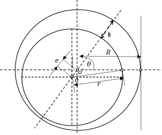
Figure 1 illustrates the bearing nomenclature. In the figure, O is the center of the shaft, O' is the center of the bearing, OO' is the line segment, e is the eccentricity, r is the radius of the shaft, R is the radius of the bearing, h is the thickness of the oil film filled with oil between the journal and shaft, and θ is the angle at an arbitrary position. The friction state of a sliding bearing can be roughly divided into three types, according to the operating conditions. In the initial condition, owing to its load, the bearing is stationary and in contact with the shaft.
Therefore, it is in a solid or dry friction state, without any lubricant between the contact surfaces. Because the friction coefficient has a value of 0.1 or higher, the frictional resistance is high, and the heat and wear are severe. As the shaft rotates, the lubricant moves between the bearing and shaft, and the pressure in the lubricant increases, owing to the squeezing effect. Hence, the shaft load is supported by the high-pressure oil region, as illustrated in Figure 10, and a thin oil film is formed. During this stage, it is said to be in a relatively frequent friction state because boundary lubrication occurs, and it is difficult to maintain complete fluid lubrication in the actual bearing. Finally, when the bearing attains a proper rotational speed, eccentricity occurs in the opposite direction of rotation, because of the wedge action of the shaft; hence, the contact surfaces of the two objects are completely separated. Because this friction is only related to the viscosity of the lubricant regardless of the material or condition of the contact surface, the friction coefficient has a value of 0.01 or less, it is the most ideal friction state.
In this study, the steady-state characteristics are analyzed by assuming that the bearing reached an appropriate rotational speed, the lubricant is properly supplied between the shaft and the bearing, and there are no changes in the properties of the lubricant.
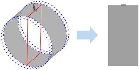
Figure 2 illustrates the modeling process of the fluid flow field of the journal bearing. The bearing consists of an oil inlet, housing, bearing liner, and a journal or shaft, as illustrated in Figure 2(a). Figure 2(b) illustrates the fluid flow field of the journal bearing, and Figure 2(c) illustrates the computational domain adopted for the numerical analysis in this study, that is, the clearance between the bearing and the shaft filled with lubricants.
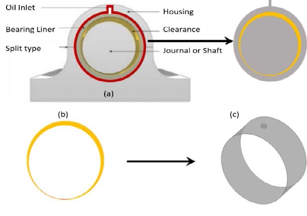
Modeling process of journal bearing flow field. (a) journal bearing, (b) flow field of journal bearing; (c) flow field model adopted for analysis
Table 1 lists the bearing dimensions and operating parameters. In this study, the analysis was performed according to the rotation speed, lubrication temperature, and eccentricity.
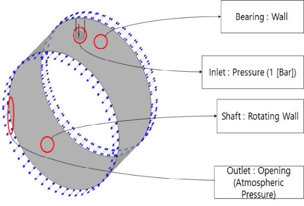
Figure 3 illustrates the boundary conditions adopted in the numerical analysis. The computational domain consists of a bearing wall, an inlet, a shaft (rotating cylindrical wall), and an opening outlet at atmospheric pressure. When the lubricant enters the inlet at a pressure of 1 bar, it rotates between the shaft and bearing, while the shaft rotates counterclockwise. The bearings to be analyzed in this study are generally oil-lubricated plain bearings that operate when completely separated from the shaft, and bearing surfaces by the lubricant film.
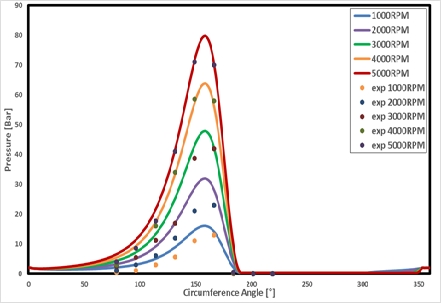
For validation, the experimental data obtained by Dhande and Pande [15] are adopted. From the grid independence test, a total of 3.2 M number of nodes is adopted. Hexagonal meshes are generated, and ANSYS 18.2 [18] is adopted for the simulation.
Figure 4 illustrates a comparison of the experimental and numerical results according to the rotational speed of the shaft. Through this comparison, the numerical results are in good agreement with the experimental data.
2.3 Parametric study on lubrication performance
When the bearing is lubricated, its efficiency is strongly related to the viscosity of the lubricant. Because the viscosity of the fluid is dominant in temperature, it is necessary to maintain the temperature by providing a suitable lubricant during the operation. The viscosity can be expressed as:
| (7) |
where T is the absolute temperature, and a and b are constants [3].
The turbine oil 30 (TP-30) utilized in this analysis changed from 50 ℃to 200 ℃. The eccentricity varies with the degree of the shaft load. Hence, three different eccentricities of 0.6, 0.8, and 0.9 are adopted at a fixed RPM of 3000. The properties of turbine oil 30 are listed in Table 2 [19].
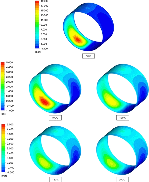
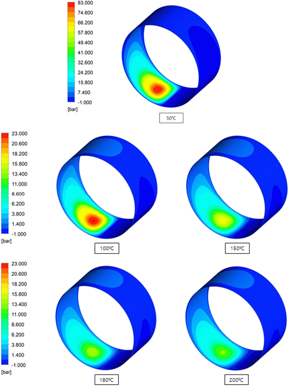
Figure 6 illustrates the pressure field with respect to the temperature change at 3000 RPM, for an eccentricity of 0.6. This indicates that as the temperature increases from 50 ℃to 200 ℃, the pressure decreases. This is because of the decrease in viscosity as the temperature increases.
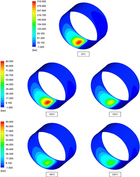
Similarly, Figures 7 and 8 illustrate the pressure field with respect to the temperature change at 3000 RPM, for eccentricities of 0.8 and 0.9, respectively. From these figures, it is evident that as the temperature increases from 50 ℃ to 200 ℃, the viscosity and pressure decrease, as illustrated in Figure 6. By analyzing the fluid flow with eccentricities of 0.6, 0.8, and 0.9, it is confirmed that the pressure decreases owing to the decrease in viscosity as the temperature increases. As the temperature decreases, the viscosity increases in the form of a log function. From the figures, it is confirmed that the pressure also changes in response to the rate of viscosity change.
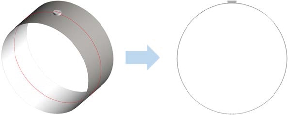
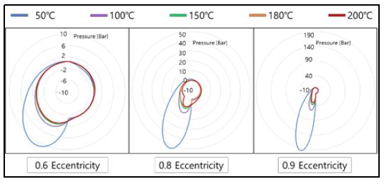
Figure 9 illustrates the plane view projection in the circumferential direction of the pressure. The figure illustrates the center line of the shaft, which is set to rotate in the counter-clockwise direction, and the corresponding circumferential pressure data applied to the bearing part is plotted for temperatures varying from 50 ℃ to 200 ℃, as illustrated in Figure 10.
Figure 10 illustrates that as the temperature increases, the magnitude of the circumferential pressure distribution decreases for eccentricities of 0.6, 0.8, and 0.9. In addition, it is evident from the analysis of the Reynolds equation for lubrication that the pressure distribution matches the theoretical pressure distribution.
Figure 11 illustrates the plane view projection along the width direction of the bearing. The shaft is rotated in the counter-clockwise direction.
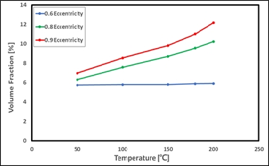
Figures 12-14 illustrate the volume fraction of lubricants in the gaseous phase on the plane, projected in the width direction of the bearing for temperature changes from 50 ℃ to 200 ℃, at a revolution of 3000 RPM, and eccentricities of 0.6, 0.8, and 0.9, respectively. When the pressure drops sharply below the vapor pressure after the minimum oil film thickness, cavitation occurs, in which the liquid lubricant changes to a gaseous state. This affects not only the lubrication performance of the bearing, but also the permissible load. After cavitation occurs, the bubbles spread along the circumferential direction, and in severe cases, impact the bearing surface, causing noise, vibration, and wear. As the bearing temperature increases, the bubbles spread less widely because of the small shear force caused by the decrease in viscosity. However, in the case of 0.6 eccentricity, the volume fraction does not change with rise in temperature, as illustrated in Figure 15.
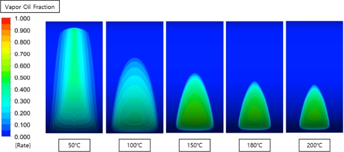
Volume fraction of the gaseous lubricant with temperature change at 3000 RPM and eccentricity of 0.6
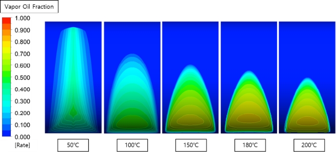
Volume fraction of the gaseous lubricant with temperature change at 3000 RPM and eccentricity of 0.8
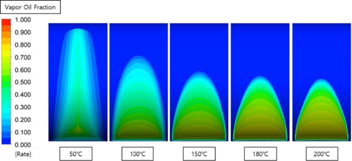
Volume fraction of the gaseous lubricant with temperature change at 3000 RPM and eccentricity of 0.9
The volume fraction increases as shown in Figure 15.
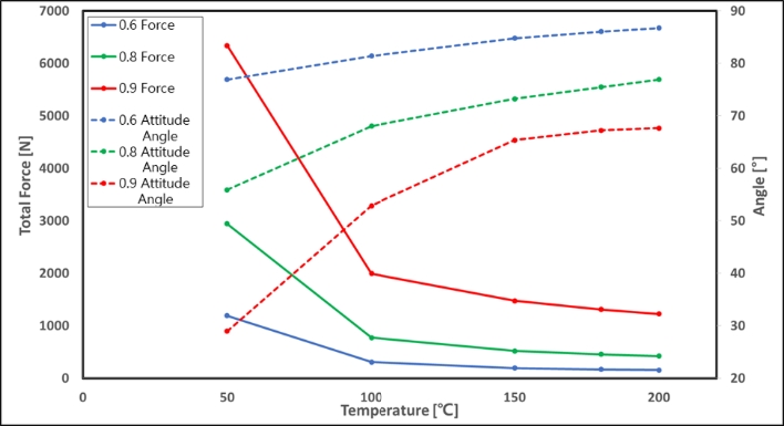
Figure 16 illustrates that the total force and attitude angle change with respect to the temperature. From the figure, it is evident that as the temperature of the lubricant increases, the pressure applied to the bearing surface decreases; thus, the reaction force applied to the shaft decreases. As the magnitude of eccentricity and combined force change, the part where the actual force acts changes, and is called the attitude angle. As the temperature increases, the force applied to the shaft decreases, and the attitude angle appears further than the minimum lubrication thickness.
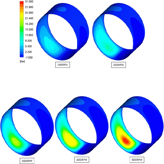
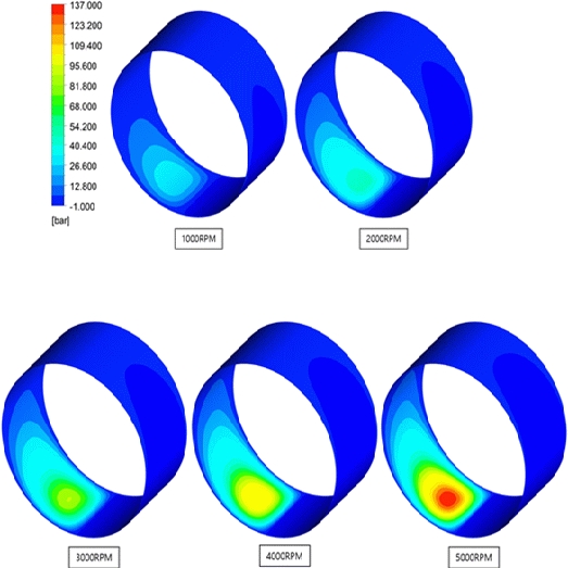
Figure 17 illustrates the pressure field with rotating speed changes from RPMs 1000 to 5000, at 50 ℃ and eccentricity of 0.6. From the figure, it is evident that as the rotating speed increases from 1000 to 5000 RPM, the pressure increases.
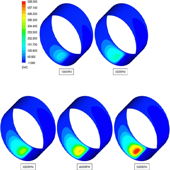
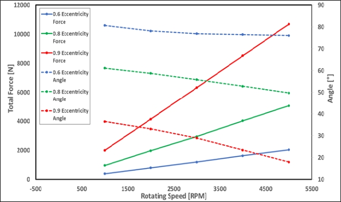
Similarly, Figures 18 and 19 illustrate the pressure field with rotating speed changes from RPMs 1000 to 5000 at 50 ℃, and eccentricities of 0.8 and 0.9, respectively. From the figures, it is evident that as the rotating speed increases from 1000 to 5000 RPM, the pressure increases similarly, as illustrated in Figure 16. In addition, as the rotating speed increases, the pressure increases in the form of a linear function, as illustrated in Figure 25.
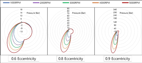
Figure 20 illustrates the corresponding circumferential pressure distribution applied to the bearing part, for rotating speeds varying from 1000 to 5000 RPMs. From the figure, it is evident that as the rotating speed increases, the magnitude of the circumferential pressure distribution increases for eccentricities of 0.6, 0.8, and 0.9.
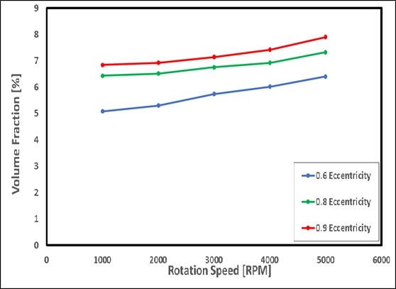
Figures 21-23 illustrate the volume fraction of the lubricant in the gaseous phase on the plane, projected in the width direction of the bearing for a revolution of 1000 to 5000 RPMs at 50 ℃, and eccentricities of 0.6, 0.8, and 0.9, respectively. When the pressure drops sharply below the vapor pressure after the minimum lubricating thickness, cavitation occurs, in which the liquid lubricant changes to a gaseous state, as illustrated in Figures 12 to 13. As the bearing rotating speed and eccentricity increase, the volume fraction increases in the form of a linear function, as illustrated in Figure 24. It also reveals that gaseous lubricant spreads more widely along the circumferential direction, because of the higher shear force caused by the increase in rotational speed.
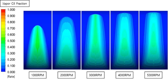
Volume fraction of the gaseous lubricant for rotating speed variation at 50℃ and eccentricity of 0.6
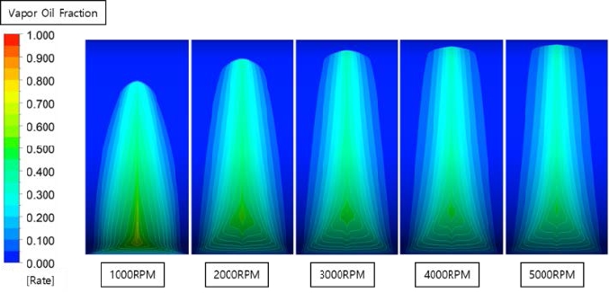
Volume fraction of the gaseous lubricant for rotating speed variation at 50℃ and eccentricity of 0.8
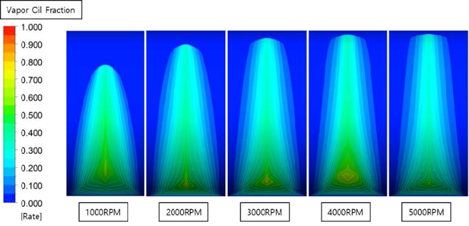
Volume fraction of the gaseous lubricant for rotating speed variation at 50℃ and eccentricity of 0.9
Figure 25 illustrates that the force and attitude angle change with respect to the rotation speed. It is evident that as the rotating speed of the shaft increases, the pressure acted on the bearing surface increases; thus, the reaction force exerted on the shaft increases. As the magnitude of eccentricity and rotational speed change, the position where the resultant force acts changes. As the rotating speed increases, the attitude angle between the vertical axis in the load direction and the line of centers, appears closer to the minimum oil film thickness.
3. Assessment of Newly Proposed Dimple Structure
When the bearing is in operation, it is difficult to maintain complete fluid film lubrication, and boundary lubrication occurs frequently. If the boundary lubrication condition is maintained, the lubrication performance decreases, owing to the higher heat generation caused by the increase in surface friction. The amount of wear and tear increases, thus resulting in a decrease in the bearing life. To address this limitation, a lubricating structure with dimples is proposed to reduce the surface friction during boundary lubrication.
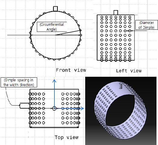
Figure 26 illustrates a schematic of the bearing with a simple dimple structure. In this study, dimple structures with various diameters are adopted in the circumferential direction, as well as in the width direction. The performance of the bearing, with and without a dimple structure, was evaluated numerically. Table 3 lists the dimple parameters adopted in this study. Six cases were presented to evaluate the performance of the bearing with a dimple structure.
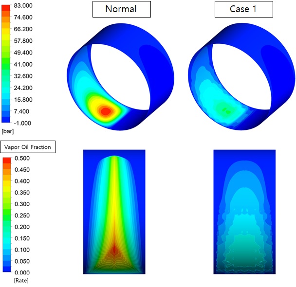
Figure 27 illustrates a comparison of the pressure field and volume fraction, with and without the dimple structure. This indicates that the pressure acting on the bearing surface is reduced by 45% in the case of a dimple structure than in a plain bearing. Moreover, the volume fraction of the gaseous lubricant decreased, owing to the reduction in the pressure drop, which could prevent the erosion caused by cavitation in advance. With the introduction of the dimple structure, the direct surface contact between the shaft and bearing is reduced. Therefore, the negative effect of the reduction in the resultant force needs to be improved. The goal is to determine a reasonable size that reduces the surface contact relatively, without sacrificing the resultant pressure force.
To compare the effect of the dimple structure in the bearing, the bearing shape, lubricant temperature of 50℃, rotational speed of 3000 RPM, and eccentricity of 0.8 are fixed, and the diameter and spatial arrangement of the dimples are altered and analyzed.
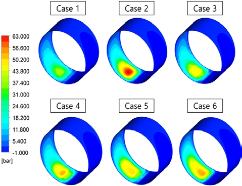
Figure 28 illustrates the pressure field according to dimple size changes at 50 ℃, with a rotational speed of 3000 RPM for an eccentricity of 0.8. From the figure, it is evident that the peak pressure of Case 2 is higher than that of the other cases. Case 1 registered the lowest peak pressure among the remaining cases.
Figure 29 illustrates the volume fraction of the gaseous lubricant in the bearing with a dimple, at a temperature of 50 ℃, rotational speed of 3000 RPM, and eccentricity of 0.8. From the figure, it is evident that Cases 2 and 6 have higher volume fractions, whereas Cases 3 and 5 have lower volume fractions.
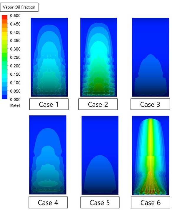
Volume fraction of the gaseous lubricant with dimple size change at 50℃, 3000 RPM and 0.8 eccentricity
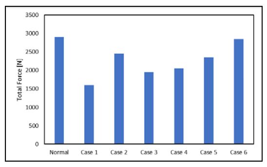
Figure 30 illustrates that Cases 2 and 6 with a 1 mm dimple diameter have relatively high total forces, compared to other cases with a dimple diameter of 2 mm. Assuming line contact between the shaft and the bearing, a dimple with a diameter of 1 mm reduces the contact area by approximately 30%. Through a comparison between Cases 2 and 6 in Figure 29, it is determined that small dimple numbers in the circumferential direction of Case 2 exert a practical total force. When compared to the normal case, Case 6 also exerts a similar total force, even though small dimples are utilized. As a result of this analysis, it is evident that changes in the shape and arrangement of the dimple have a significant influence on the performance of the bearing, and more reasonable shapes can be discovered through further parametric studies.
4. Conclusion
The lubrication of the bearing is a complex mechanism in which the changes in temperature, eccentricity, and the force acting on the shaft are mutually dependent. In this study, the dimple effect in a journal bearing was investigated. The dimple structure reduces the contact area between the shaft and bearing, and the volume fraction causes cavitation erosion inside the bearing. This indicates that by introducing the dimple structure on the bearing surface, the lubrication performance improved, when compared to that of the plain bearing. Various parameters such as temperature, rotational speed, and eccentricity affecting lubrication have also been investigated.
The results indicated that when the eccentricity and rotational speed increased, and the lubricant temperature decreased, the pressure on the bearing increased. When the temperature increased, the viscosity of the lubricant decreased in the form of a log function. Hence, it is important to manage the temperature of the lubricant.
As the pressure increased with changes in temperature, eccentricity, and rotational speed, the attitude angle of the resultant force moved close to the minimum oil film thickness.
By introducing the dimple structure, the direct contact between the shaft and bearing can be reduced by approximately 30%, while maintaining the resultant force constant. In addition, the volume fraction reduction prevents erosion caused by cavitation inside the bearing.
Acknowledgments
This work was supported by a Research Grant of Pukyong National University (2019). This paper is a revised and expanded version of a paper entitled ‘Numerical study on the Evaluation of lubrication performance of journal bearing with shape deformation’ presented at the 44th KOSME fall conference 2020 and is also a part of the first author’s master thesis.
Author Contributions
Conceptualization, Y. W. Lee; Methodology, Y. W. Lee; Software, K. H. Kim; Formal Analysis, K. H. Kim; Investigation, K. H. Kim; Resources, Y. W. Lee; Data Curation, K. H. Kim and Y. W. Lee; Writing-Original Draft Preparation, K. H. Kim; Writing-Review & Editing, Y. W. Lee; Visualization, K. H. Kim; Supervision, Y. W. Lee; Project Administration, Y. W. Lee; Funding Acquisition, Y. W. Lee.
References
-
E. N. D. C. Andrade, “On the viscous flow in metals, and allied phenomena,” Proceedings of the Royal Society of London Series A, vol. 84, no. 567, pp. 1-12, 1910.
[https://doi.org/10.1098/rspa.1910.0050]

-
W. F. Hughes and F. Osterle, “Temperature effects in journal bearing lubrication,” ASLE Transactions, vol. 1, no. 1, pp. 210-212, 1958.
[https://doi.org/10.1080/05698195808972331]

-
E. N. C. Andrade, XLI. A theory of the viscosity of liquids. - Part I, The London, Edinburgh, and Dublin Philosophical Magazine and Journal of Science, vol. 17, no. 112, pp. 497-511, 1934.
[https://doi.org/10.1080/14786443409462409]

-
A. A. Raimondi and J. Boyd, “A solution for the finite journal bearing and its application to analysis and design: III,” ASLE Transactions, vol. 1, no. 1, pp. 194-209, 1958.
[https://doi.org/10.1080/05698195808972330]

-
F. K. Orcutt and E. B. Arwas, “The steady-state and dynamic characteristics of a full circular bearing and a partial arc bearing in the laminar and turbulent flow regimes,” vol. 89, no. 2, 1967.
[https://doi.org/10.1115/1.3616932]

-
M. I. Ermolaev, V. V. Batishchev, and K. Goryachev, “Investigation of the vapor pressure of lubricating oils,” Chemistry and Technology of Fuels and Oils, vol. 8, no. 5, pp. 388-390, 1972.
[https://doi.org/10.1007/BF00719075]

-
Y. I. Kvitnitsky, N. F. Kirkatch, and Y. D. Poltavsky, “The solution of Reynolds equation under natural boundary conditions for hydrodynamic journal bearings,” Wear, vol. 37, no. 2, pp. 217-231, 1976.
[https://doi.org/10.1016/0043-1648(76)90029-6]

-
S. Uhkoetter, and et al., “Development and validation of a three-dimensional multiphase flow CFD analysis for journal bearings in steam and heavy duty gas turbines,” Journal of Engineering for Gas Turbines and Power, vol. 134, no. 10, 2012.
[https://doi.org/10.1115/1.4007078]

- Tauviqirrahman, M., J. Jamari, and A.P. Bayuseno.” A comparative study of finite journal bearing in laminar and turbulent regimes using CFD (computational fluid dynamic),” in MATEC web of conferences, 2016, EDP Sciences.
-
S. Aksoy and M. F. Aksit, “A fully coupled 3D thermo-elastohydrodynamics model for a bump-type compliant foil journal bearing,” Tribology International, vol. 82, Part A, pp. 110-122, 2015.
[https://doi.org/10.1016/j.triboint.2014.10.001]

-
M. Farrall, and et al., “A numerical model for oil film flow in an aero-engine bearing chamber and comparison with experimental data,” Turbo Expo: Power for Land, Sea, and Air, pp. 409-417, 2004.
[https://doi.org/10.1115/GT2004-53698]

-
D. Y. Dhande and D. W. Pande, “A two-way FSI analysis of multiphase flow in hydrodynamic journal bearing with cavitation,” Journal of the Brazilian Society of Mechanical Sciences and Engineering, vol. 39, pp. 3399-3412, 2017.
[https://doi.org/10.1007/s40430-017-0750-8]

-
K. P. Gertzos, P. G. Nikolakopoulos, and C. A. Papadopoulos, “CFD analysis of journal bearing hydrodynamic lubrication by Bingham lubricant,” Tribology International, vol. 41, no. 12, pp. 1190-1204, 2008.
[https://doi.org/10.1016/j.triboint.2008.03.002]

-
G. Gengyuan, and et al., “CFD analysis of load-carrying capacity of hydrodynamic lubrication on a water-lubricated journal bearing,” Industrial Lubrication and Tribology, vol. 67, no. 1, pp. 30-37, 2015.
[https://doi.org/10.1108/ilt-03-2013-0028]

-
J. Sun and G. Changlin, “Hydrodynamic lubrication analysis of journal bearing considering misalignment caused by shaft deformation,” Tribology International, vol. 37, no. 10, pp. 841-848, 2004.
[https://doi.org/10.1016/j.triboint.2004.05.007]

-
D. Y. Dhande and D. W. Pande, “Multiphase flow analysis of hydrodynamic journal bearing using CFD coupled fluid structure interaction considering cavitation,” Journal of King Saud University-Engineering Sciences, vol. 30, no. 4, pp. 345-354, 2018.
[https://doi.org/10.1016/j.jksues.2016.09.001]

- H. K. Versteeg and W. Malalasekera, An introduction to computational fluid dynamics, 2nd edition, Pearson Education Limited, 2007.
- ANSYS, Release 18.2, ANSYS CFX-Solver Modeling Guide, ANSYS Inc, 2018.
- https://www.lotos.pl/en/859/p,793,c,570/for_business/industrial_lubes/turbine_oils/turbine_oil_t-30#tab-1, , Accessed April 5, 2020.

