Numerical investigation on incompressible fluid flow and heat transfer of porous media using Lattice Boltzmann method
Copyright © The Korean Society of Marine Engineering
This is an Open Access article distributed under the terms of the Creative Commons Attribution Non-Commercial License (http://creativecommons.org/licenses/by-nc/3.0), which permits unrestricted non-commercial use, distribution, and reproduction in any medium, provided the original work is properly cited.
Abstract
Fluid flow and heat transfer in porous media are critical in many industrial applications; therefore, insight into problems associated with porous media is important for understanding their characteristics. In this study, the Lattice Boltzmann equation is combined with the Brinkman–Forcheimer equation, which contains a forcing term including porosity, to predict fluid flow and heat transfer in porous media. For a two-dimensional square porous cavity, parameters such as the Reynolds, Darcy, and Rayleigh numbers are considered to analyze fluid flow and heat transfer characteristics. The results show that variations in the Darcy number significantly affect the natural convective flow structure, heat transfer characteristics, and boundary layer thickness. Meanwhile, a high Rayleigh number significantly affects the fluid flow and heat transfer when the Darcy number is relatively small.
Keywords:
Computational fluid dynamics, Lattice Boltzmann method, Porous media, Darcy number, Rayleigh number1. Introduction
Fluid flow and heat transfer in porous media are important phenomena in many engineering systems owing to their wide applications in different fields. Porous media are composed of polyphase materials in an empty area within solid particles, where fluid can flow. The physical properties of porous media should be associated with two or more parameters such that a relationship can be realized to allow fluid flow through porous media [1]. Fluid dynamics in porous media have been applied in various industrial applications such as solid matrices, microporous heat exchangers, electronic cooling, chemical catalytic reactors, heat pipe technology, filtering, food processing, fuel cells, air heaters, insulation, porous bearings, solar collectors, and nuclear reactors [2]. Therefore, theoretical, experimental, and numerical studies pertaining to porous media have been conducted to obtain a better understanding of the underlying mechanism, and simulations of fluid flow fields inside porous media are necessitated [3]. Darcy’s equation has been broadly applied to investigate fluid dynamics in porous media. For low velocities, Darcy’s equation can be used to understand fluid dynamics. However, for high velocities, the theoretical results are not consistent with experimental results [4]. Nonlinear effects and viscous stresses should be considered in the study of fluid flow. In cases involving high porosity, Brinkman’s equation is suitable for analyzing porous media [5]. Meanwhile, Forchheimer’s equation has not been validated for high porosity cases [6]. Using the local volume averaging method, Brinkman–Forchheimer’s formula, which incorporates linear and nonlinear drag, was developed to solve the body force, although it was difficult to combine the two abovementioned parameters [7]. The capability of the Brinkman–Forchheimer formula for accurately determining fluid flow characteristics in non-Darcy flows has been investigated using conventional numerical techniques [8]. The Lattice Boltzmann method (LBM), as an alternative numerical method, has garnered significant attention for simulating complex geometries [9].
The aim of the present study is to evaluate the fluid flow and heat transfer characteristics in a square porous cavity with a moving wall and adiabatic walls. In this study, an LBM code, including the Brinkman–Forchheimer formula, was developed to investigate fluid flow and heat transfer in a two-dimensional square porous cavity.
2. Numerical Methods
2.1 Governing Equations
To analyze fluid dynamics in isotropic and homogeneous porous media, the governing equations for the generalized non-Darcy model under the equilibrium condition for incompressible flow are as follows [3]:
| (1) |
| (2) |
where u is the velocity vector, p the pressure, ρ the fluid density, e the porosity, and ve the effective kinematic viscosity. The porosity and effective kinematic viscosity are defined as follows:
| (3) |
| (4) |
where cs, rt, and Δt are the speed of sound, relaxation time, and time step, respectively. In addition, the last term F in the momentum equation represents the total force due to the porous medium and other external forces, and it is expressed as
| (5) |
where v is the kinematic viscosity of the fluid. Moreover, on the right side of Equation (5), the first term represents the frictional resistance of the fluid and porous media skeleton, and the second term the inertia due to the presence of a porous medium. For flows over spherical particles, the permeability K can be defined as [13]
| (6) |
where dp is the solid particle diameter. The velocity magnitude |u| can be calculated as follows:
| (7) |
where ux and uy are the velocity components in the x-and y-directions, respectively. The geometric function Fɛ can be evaluated using Ergun’s empirical formula as follows [13]:
| (8) |
The last term in Equation (5), G, is the body force, which can be written as
| (9) |
where g is the gravity, T0 the average temperature of the system, and β the thermal expansion coefficient.
The energy equation of convective heat transfer in porous media can be expressed as
| (10) |
where T is the temperature of the fluid, and σ is the heat capacity ratio between the solid and fluid phases. The heat capacity ratio can be written as
| (11) |
where ρs, ρf and cps, cpf are the density and specific heat of the solid and fluid phases, respectively. In addition, the effective thermal diffusivity αe can be calculated as follows:
| (12) |
To represent the characteristics of convective heat transfer in porous media, we used several dimensionless numbers, i.e., the Reynolds number Re, Prandtl number Pr, Darcy number Da, viscosity ratio J, length L, and Rayleigh number Ra. Each dimensionless number is defined as follows:
| (13) |
| (14) |
| (15) |
| (16) |
| (17) |
where ΔT = Th - Tc is the temperature difference between the hot and cold sidewalls.
2.2 Thermal Lattice Boltzmann Method
The distribution functions of the LBM model used to solve the kinetic equations for the flow field can be written as follows:
| (18) |
where fk is the particle distribution function, x the position, and Δx the Lattice spacing. For a D2Q9 model, the discrete velocities ck are calculated as follows:
The weight factors are wk = 4/9 for k = 0, wk = 1/9 for k = 1–4, and wk = 1/36 for k = 5–8. The speed of sound in this model is cs = c/√3. Here, c = Δx/Δt is the Lattice speed and is set to 1 (Δx = Δt) in this study. Similarly, the equilibrium distribution function can be written as
| (19) |
In a porous medium, an internal force is exerted in the domain owing to the presence of porosity, and it is expressed as follows:
| (20) |
The particle density and actual velocity can be calculated using the molecular distribution function, as follows:
| (21) |
where v is the temporal velocity; c0 and c1 are constants calculated as shown below.
| (22) |
| (23) |
| (24) |
Equation (10) can be solved using an auxiliary Lattice Boltzmann equation, as follows:
| (25) |
where gk is the temperature distribution function, rt the relaxation time, and the equilibrium distribution function, which is defined as
| (26) |
Hence, the governing equations, i.e., Equations (1), (2), and (10), can be solved using these Lattice Boltzmann formulas to analyze the fluid flow and heat transport in porous media.
2.3 Boundary conditions
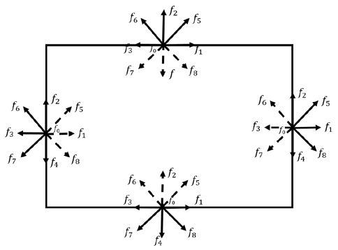
In all wall boundaries, the bounce back boundary condition for a D2Q9 model is adopted, as illustrated in Figure 1.
| (27) |
The bounce-back boundary condition (adiabatic) was used on the top and bottom of the boundaries. Therefore, the following conditions are imposed, as illustrated in Figure 2.
| (28) |
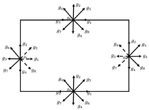
Illustration of boundary conditions for heat transfer. Continuous and dashed lines represent known and unknown distribution functions at wall, respectively.
The temperature distributions at the cold wall are calculated as follows:
| (29) |
| (30) |
| (31) |
The temperature distributions at the hot wall are calculated as follows:
| (32) |
| (33) |
| (34) |
3. Description of problems
3.1 Porous cavity with moving wall
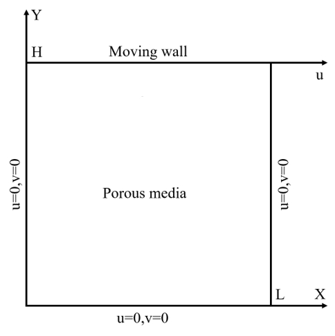
In this study, a square cavity with fully porous media was considered to analyze the fluid flow characteristics; the top wall was modeled as moving, whereas the other walls were fixed, as shown in Figure 3. In the figure, H and L represent the height and length of the square porous cavity (H/L=1), respectively. The fluid in the domain exhibited a Newtonian, incompressible, and laminar flow. The parameters considered to analyze the fluid flow behavior in the square porous cavity are summarized in Table 1. The moving wall velocity was selected arbitrarily, and the viscosity was calculated using the relaxation time, which is associated with the Re. The lattice unit and time step were defined based on the LBM principles. The density of the fluid was considered to be unity. A domain measuring 100 × 100 lattice units was used for the fluid flow analysis. The simulation time was set to 100,000 time steps to reach a steady state.
3.2 Porous cavity with adiabatic walls
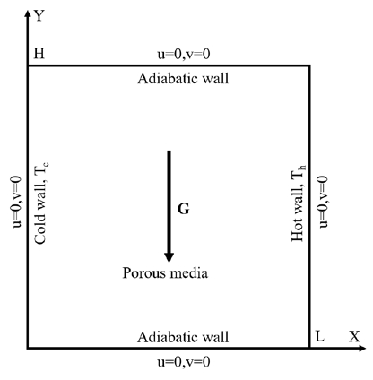
The fluid domain was considered as a cold wall on the left side and a heated wall on the right side to analyze the convective heat transfer characteristics, as shown in Figure 4. In addition, the two horizontal walls were adiabatic. A numerical study was performed for this fluid domain for different Ra and Da, and a constant porosity. The finite difference method [8] was used as a reference to verify the average Nusselt number in the present study. A domain measuring 128 × 128 lattice units was used in this study. The characteristic speed in convective heat transfer is proportional to , and it should be less than approximately 0.1 for a good approximation. Therefore, the relaxation time rt employed was consistent with the various Ra, Da, and porosity for the lattice Boltzmann equations. The calculation time was set to 150,000 time steps. Three different cases were considered to investigate heat transfer porous media, as listed in Table 2.
4. Results and Discussions
4.1 Fluid flow analysis in porous cavity
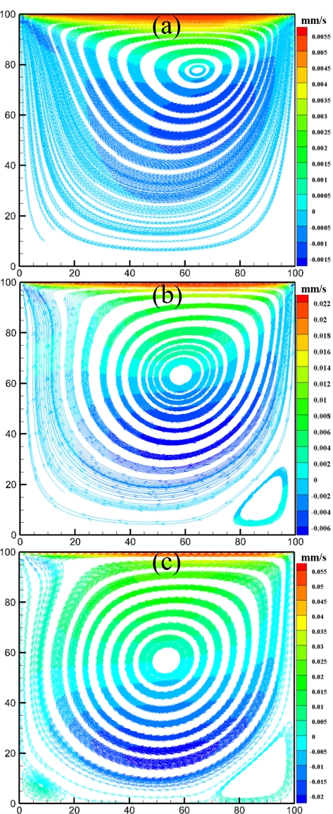
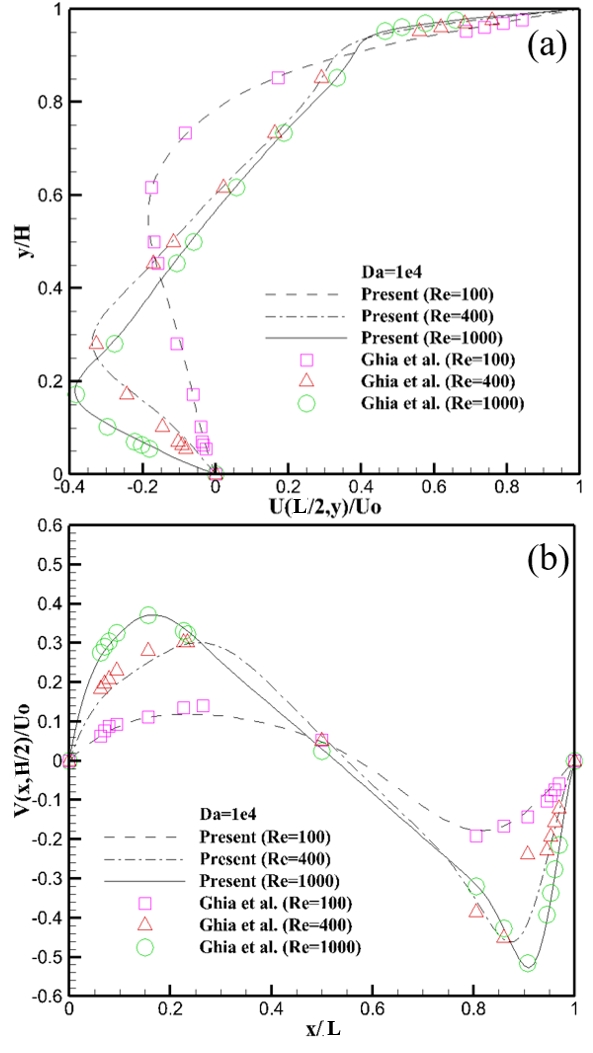
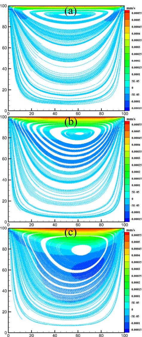
The simulation was performed based on a fully porous cavity, where the porosity (e = 0.99) and Da (Da = 104) were set to constant values for different Re (Re = 100, 400, and 1000) to achieve an ideal porous cavity flow. The velocity streamlines for different Re are shown in Figure 5. The fluid velocity in the porous media increased with Re. Therefore, the fluid can flow easily through the porous media. When Re was low, a small vortex was formed near the moving wall, as shown in Figure 5 (a). As Re increased, the fluid vortex shifted toward the center of the cavity. A secondary vortex was generated at the bottom corners of the cavity owing to the rapid motion of the fluid. The results of the velocity profiles for Re = 100, 400, and 1000 were plotted along the centerline of the cavity, as presented in Figure 6. The velocity profiles obtained in the present study agreed well with those of Ghia et al. [10].
The effects of Da was investigated for a low Re (Re = 10) and porosity (e = 0.1). To visualize the fluid flow behaviors, the velocity streamlines for different Da are presented, as shown in Figure 7. As shown in Equation (13), Da is directly proportional to the permeability. Therefore, it can be inferred that when Da is low, the permeability of the porous media will be low. Figure 7 (a) shows that when Da is low, vortex flow occurred near the moving wall; this is because a low Da restricts fluid flow owing to the lower permeability. By contrast, a high Da increases the permeability, resulting in an increase in the fluid velocity throughout the cavity; consequently, the vortex becomes stronger and tends to move to the center of the cavity.
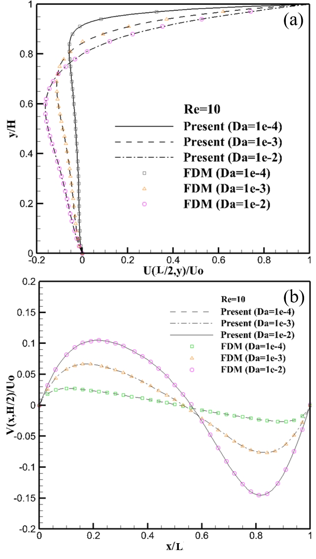
Figure 8 shows the velocity profiles for various Da at the mid-height of the cavity. As shown, the LBM results agreed well with the FDM results. It was observed that, for a low Da, the velocity boundary layer thickness near the moving wall became linear owing to the slow motion of the fluid. As Da increased, the velocity boundary layer thickness increased, and the vortex flow shifted toward the center from the moving wall, which indicates that the fluid can flow easily through porous media with increasing permeability or Da.
4.2 Convective heat transfer analysis for porous cavity
Streamlines and isotherms for different Ra were obtained for Case 1 described in Table 2, as shown in Figures 9 and 10. Figure 9 shows that the shape of the fluid circulation was almost symmetric for the lower Ra = 103 owing to the low bouncy force, although fluid flow motion commenced. As Ra increased, the fluid circulation throughout the cavity increased because of the high bouncy force. Therefore, the fluid flow and isotherm patterns changed gradually with increasing Ra; consequently, the fluid flow patterns became elliptical, the isotherm changed from nearly vertical to an s-shape, and the velocity and thermal boundary layer thicknesses near the two vertical walls became thinner.
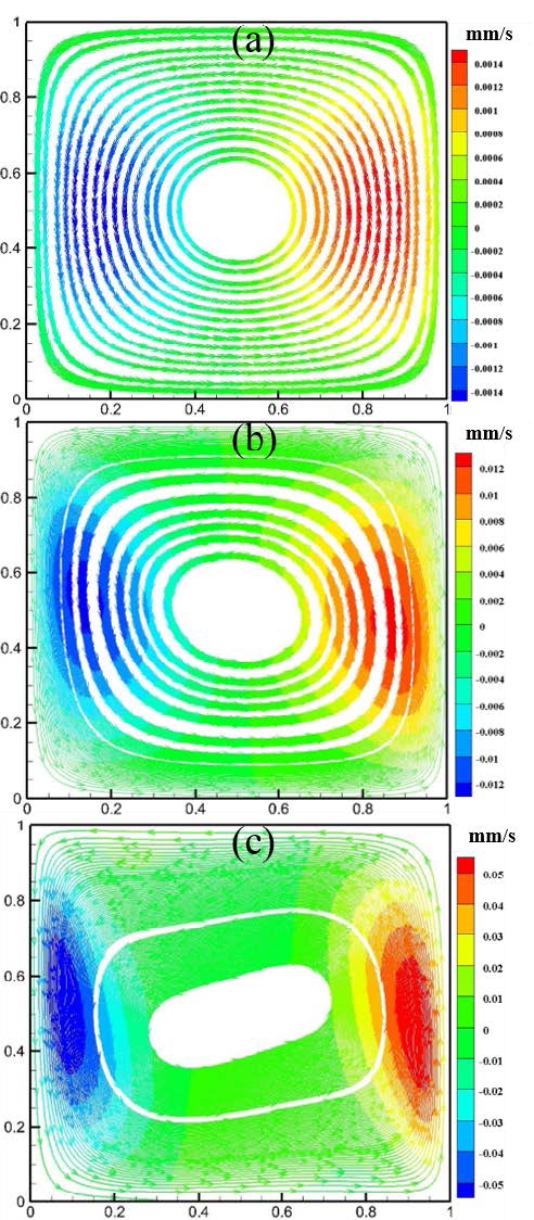
Streamlines in cavity for e = 0.4 and Da = 10-2 (Case 1): (a) Ra = 103, (b) Ra = 104, and (c) Ra = 105
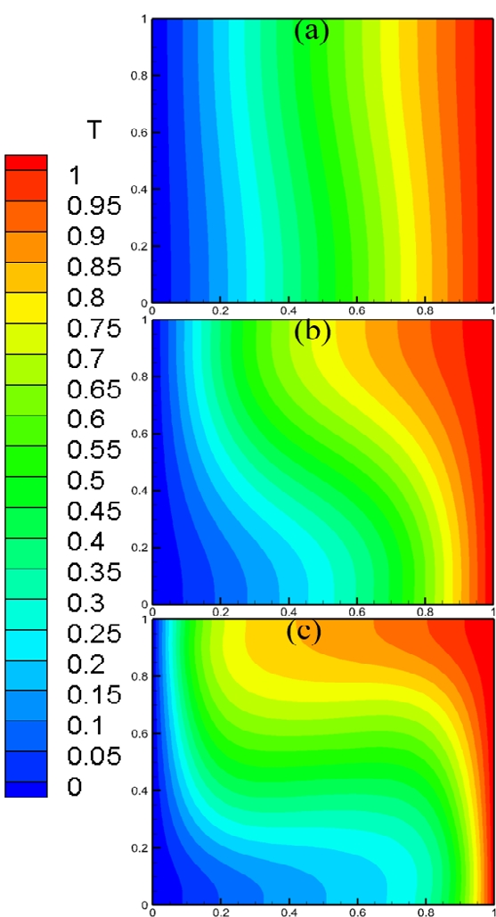
Isotherms in cavity for e = 0.4 and Da = 10-2 (Case 1): (a) Ra = 103, (b) Ra = 104, and (c) Ra = 105
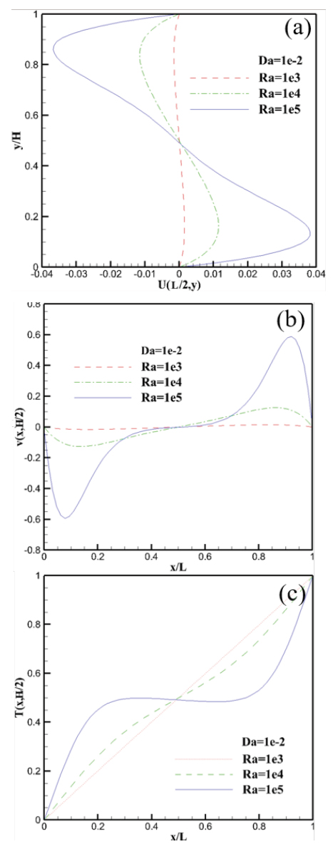
Generally, in cases involving an increase in Ra, the buoyant force causes an increase in the shear stresses near the wall, which consequently results in more turbulence inside the cavity and hence heat transfer improvement. Figures 11 shows that heat transfer occurred primarily by conduction between the high (right) and low (left) temperature walls for low Ra, owing to the few velocities and the linear temperature profile. As Ra increased, the heat transfer mechanism in the cavity changed from conduction to convection because the buoyancy force increased the velocity magnitude.
Figures 12 to 14 show the streamline, isotherm, velocity, and temperature profiles for Case 2, respectively. The Da of Case 2 was 100 times lower than that of Case 1. Based on definition, Da is related to the permeability of the fluid flow; therefore, the permeability in porous media of decreases with Da. As such, the resistance of the fluid flow in Case 2 would be higher than that of Case 1. Consequently, the pattern shown in Figure 13 (a) is similar to that in Figure 12 (a); however, the Ra of Case 1 was 100 times lower than that of Case 2. This implies that a high Ra must overcome the relatively high flow resistance of low Da flows.
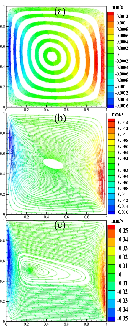
Streamlines in cavity for e = 0.4 and Da = 10-4 (Case 2): (a) Ra = 105, (b) Ra = 106, and (c) Ra = 107
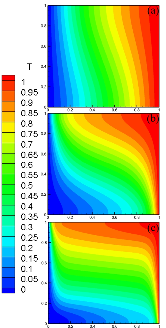
Isotherms in cavity for e = 0.4 and Da = 10-4 (Case 2): (a) Ra = 105, (b) Ra = 106, and (c) Ra = 107
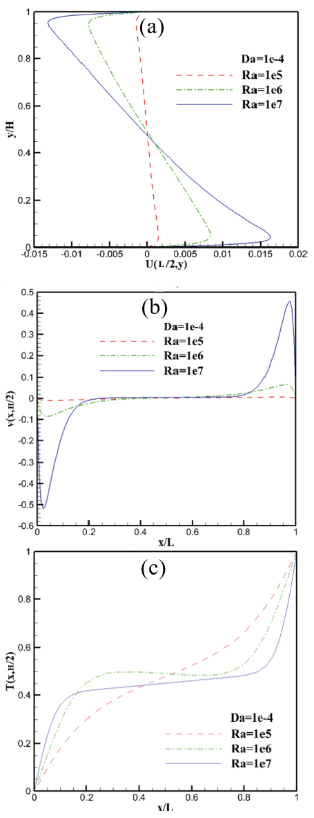
Velocity and temperature profiles in cavity: (a) Horizontal velocity profile, (b) vertical velocity profile, and (c) temperature profile (Case 2)
Figure 12 shows that the overall flow patterns of Case 2 were different, and that the centers of the vortex were located relatively near the left wall compared with Case 1. Figures 13 and 14 show that the isotherm and velocity and temperature distribution were relatively similar to those of Case 1 (as shown in Figures 10 and 11).
The average Nusselt numbers of the left (or right) walls of Cases 1 and 2 were obtained to compare the LBM with the conventional FDM [8], as shown in Table 3. The average Nusselt number of the left (or right) square porous cavity was calculated as follows:
| (36) |
As shown in Table 3, the results of the LBM agreed well with those of the conventional FDM.
Figures 15 to 17 show the streamlines, isotherms, velocities, and temperature distributions for Case 3, respectively. As Da increased, the thermal boundary layers near the vertical walls became thinner due to less flow resistance, and more convective mixing occurred in the interior of the cavity.
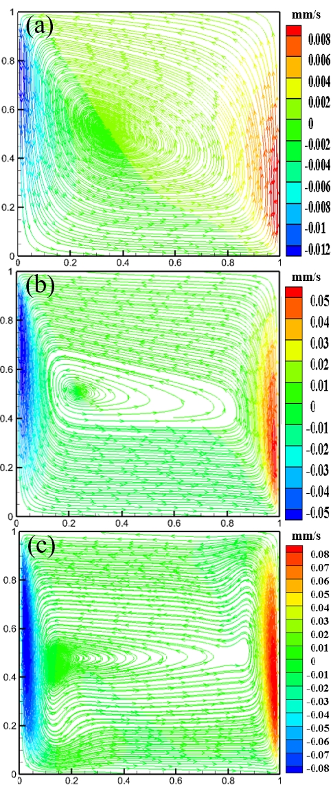
Streamlines in cavity for e = 0.4 and Ra = 107 (Case 3): (a) Da = 10-3, (b) Da = 10-4, and (c) Da = 10-5
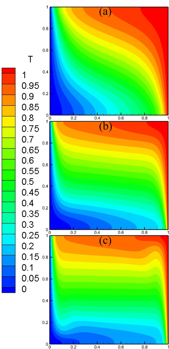
Isotherms in cavity for e = 0.4 and Ra = 107 (Case 3): (a) Da = 10-3, (b) Da = 10-4, and (c) Da = 10-5
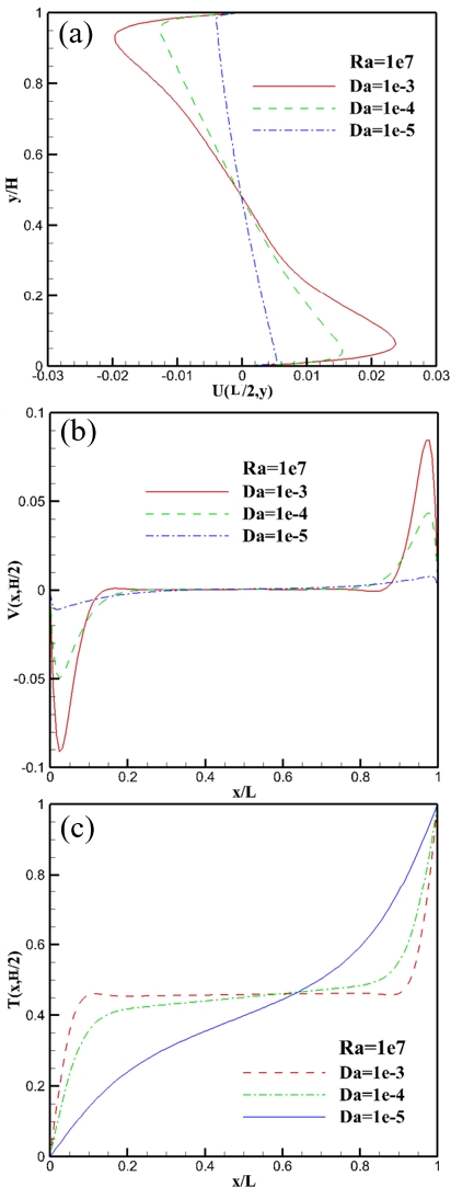
Velocity and temperature profiles in cavity: (a) Horizontal velocity, (b) vertical velocity, and (c) temperature profiles (Case 3)
Figures 17 (a) and (b) show that the velocity indicated a peak near the hot and cold walls, and the peak of the velocity profile increased and became sharper as Da increased. The temperature distribution along the horizontal midline is shown in Figure 17 (c). The temperature distribution at Da = 10-3 was almost similar to that at Da = 10-4. As Da decreased, the temperature profile near the wall changed slowly owing to the decreased convection effect caused by the lower fluid velocity. The phenomena observed from the velocity and temperature profiles show that the flow pattern and convective heat transferred in the case with Da = 10-5 were similar to Case 1 with Da = 10-2 and Ra = 104. This implies that Da significantly affects the fluid flow behavior.
5. Conclusion
In this study, the LBM code combined with the Brinkman–Forchheimer formula was developed to investigate fluid flow and heat transfer characteristics in porous media. For a two-dimensional square porous cavity, parameters such as Re, Da, and Ra were considered to analyze fluid flow and heat transfer characteristics. It was discovered that the results obtained using the LBM were consistent with those obtained using the FDM; hence, the LBM is a good approach in porous media research.
The simulation results obtained in this study were as follows:
- 1) When Re was low, vortex formation was observed near the moving wall, as shown in Figure 5 (a). As Re increased, the fluid vortex shifted toward the center of the cavity, and a secondary vortex appeared in the bottom corners of the cavity owing to the rapid motion of the fluid.
- 2) As Da increased, the velocity boundary layer thickness increased, and the vortex flow shifted toward the center from the moving wall; this indicates that the fluid flowed easily through the porous media with increasing permeability or Da.
- 3) As Ra increased, the heat transfer mechanism in the cavity changed from conduction to convection because the buoyancy force increased the velocity magnitude.
- 4) As Da increased for a fixed Ra, the thermal boundary layers near the vertical walls became thinner because of the lower flow resistance and more convective mixing in the interior of the cavity.
In summary, the simulation results showed that variations in Da significantly affected the natural convective flow structure, heat transfer characteristics, and boundary layer thickness. Meanwhile, a high Ra affected the fluid flow and heat transfer significantly when Da was relatively low.
Acknowledgments
This work was supported by Korea Institute of Energy Technology Evaluation and Planning (KETEP) grant funded by the Korean government (No. 20184010201700).
Author Contributions
Conceptualization, P. Chakma and Y. W. Lee; Methodology, P. Chakma; Software, P. Chakma; Formal Analysis, P. Chakma; Investigation, P. Chakma; Resources, P. Chakma; Data Curation, P. Chakma; Writing-Original Draft Preparation, P. Chakma; Writing-Review & Editing, P. Chakma and Y. W. Lee; Visualization, P. Chakma; Supervision, Y. W. Lee; Project Administration, Y. W. Lee; Funding Acquisition, Y. W. Lee.
References
- Mechanics of Hydraulic Fracturing, http://www.frackoptima.com/userguide/theory/fluidflow-porousmedium-carter.html, , 10.08.2021.
-
Z. Ma, L. Duan, S. Yao, and X. Jia, “Numerical study of natural convection heat transfer in porous media square cavity with multiple cold walls based on LBM,” International Journal of Heat and Technology, vol. 33, no. 4, pp. 69-76, 2015.
[https://doi.org/10.18280/ijht.330409]

-
Q. Liu and Y. -L. He, “Lattice Boltzmann simulations of convection heat transfer in porous media,” Physica A: Statistical Mechanics and its Applications, vol. 465, pp. 742-753, 2017.
[https://doi.org/10.1016/j.physa.2016.08.010]

- D. Henry, Report to the Minister of Public Works on Paving and Pavement Macadamizing London and Paris, Paris, France, 1856 (in French).
-
H. C. Brinkman, “A calculation of the viscous force exerted by a flowing fluid in a dense swarm of particles,” Applied Science Research, vol. 1, pp. 27-34, 1949.
[https://doi.org/10.1007/BF02120313]

- P. Z. Forchheimer, “Movement of water through the ground,” Journal of the Association of German Engineers, vol. 45, pp. 1781-1788, 1901 (in German).
- A. Bejan and D. A. Neild, Convection in porous media, New York, USA, Springer, 1992.
-
P. Nithiarasu, K. N. Seetharamu, and T. Sundararajan, “Natural convective heat transfer in a fluid saturated variable porosity medium,” International Journal of Heat and Mass Transfer, vol. 40, no. 16, pp. 3955-3967, 1997.
[https://doi.org/10.1016/S0017-9310(97)00008-2]

-
T. Seta and K. Kono, “Thermal Lattice Boltzman method for liquid-gas two-phase flows in two dimension,” JSME International Journal series B, vol. 47, no. 3, pp. 572-583, 2004.
[https://doi.org/10.1299/jsmeb.47.572]

-
U. Ghia, K. N. Ghia, and C. T. Shin, “High-Re solutions for incompressible flow using the Navier-Stokes equations and a multigrid method,” Journal of computational physics, vol. 48, no. 3, pp. 387-411, 1982.
[https://doi.org/10.1016/0021-9991(82)90058-4]

-
S. -G. Yao, L. -B. Duan, Z. -S. Ma, and X. -W. Jia, “The study of natural convection heat transfer in a partially porous cavity based on LBM,” The Open Fuels & Energy Science Journal, vol. 7, pp. 88-93, 2014.
[https://doi.org/10.2174/1876973X01407010088]

-
G. P. Lauriat and V. Prasad, “Non-Darcian effects on natural convection in a vertical porous enclosure,” International Journal of Heat and Mass Transfer, vol. 32, no. 11, pp. 2135-2148, 1989.
[https://doi.org/10.1016/0017-9310(89)90120-8]

- S. Ergun, “Flow through packed columns,” Chemical Engineering Progress, vol. 48, no. 2, pp. 89-94, 1952.
-
Z. Guo and T. S. Zhao, “Lattice Boltzmann model for incompressible flows through porous media,” Physical review E, vol. 66, pp. 036304-9, 2002.
[https://doi.org/10.1103/PhysRevE.66.036304]


