Structure modifications of crankcase explosion relief valve for cost savings in large ship engines
Copyright © The Korean Society of Marine Engineering
This is an Open Access article distributed under the terms of the Creative Commons Attribution Non-Commercial License (http://creativecommons.org/licenses/by-nc/3.0), which permits unrestricted non-commercial use, distribution, and reproduction in any medium, provided the original work is properly cited.
Abstract
A crankcase explosion relief valve (ERV) is installed to prevent accidents caused by explosions inside the crankcase of marine engines. Engine manufacturers demand lower prices of parts due to declining shipbuilding and engine prices. PROSAVE developed an ERV for a 30% cost saving. The developed ERV is the largest product to be installed in marine diesel engines. In this study, structural analysis was conducted on the ERV, and the radial displacement and von Mises stress were within the allowable range. An explosion test was performed according to criteria set by the International Association of Classification Societies (IACS) to evaluate the performance of the ERV. The test results show that the difference between the reference pressure and explosion pressure satisfies the IACS reference value, and the ERV was sufficiently airtight after the explosion. Flames did not spread outside during the explosion, the temperature rise in the flame arrester was acceptable, and there was no damage to the components. According to the performance test results, the ERV developed by PROSAVE satisfied the criteria required by the IACS, and the ERV showed a reliable performance at a 30% production cost saving.
Keywords:
Crankcase explosion relief valve, Cost saving, Structure modification, Performance test, Large ship engines1. Introduction
Explosions caused by oil mist inside the crankcase of marine diesel engines can cause damage to the engine as well as human casualties. Therefore, crankcase explosion relief valves (ERVs) are installed in diesel engines to prevent such accidents [1].
Computational fluid dynamics (CFD) has been used to study the occurrence of explosions in exhaust systems in ships using liquefied petroleum gas (LPG) as fuel. The results of the numerical analysis can be used to design the safety device of the exhaust system in LPG ships [2]. In addition, CFD has been used to analyze explosion accidents occurring in ships using liquefied natural gas (LNG) as fuel. The explosion pressure can be predicted using an explosion analysis [3]. To develop a relief valve, it is necessary to conduct a numerical analysis, and to analyze the flow characteristics of the relief valve using CFD [4]. Previous studies have performed analyses related to flow and explosions using CFD, however this study conducted a structural analysis of the manufacturing cost savings of an ERV.
Advanced research has been conducted to analyze the structure of the ERV. Jiang et al. [5] analyzed the structure of the flame arresters of crankcase ERVs and suggested a guide for their design. Lee et al. [6] conducted a structural analysis on the crankcase ERV spring of LNG-fueled ships and proposed an application method in the field where it is difficult to apply the coil spring because of the narrow space.
As aforementioned, the previous research has studied the ERV of the crankcase to evaluate the performance, however the ERV of the intake and exhaust system was not analyzed. This study focused on the structural analysis of ERVs applied to intake and exhaust systems. Structural analysis was also conducted to reduce manufacturing costs.
The provisions related to ERVs are specified in UR M9 and UR M66 by the International Association of Classification Societies (IACS). IACS UR M9 specifies the installation of ERVs for marine diesel engines and the compulsory installation of ERVs for internal combustion engines with a cylinder bore of 200 mm and above [7]. IACS UR M66 defines the test materials and methods for crankcase explosion relief valves [8]. MAN Energy Solutions who are engine manufacturers, approve products that meet the criteria of the IACS regulations [9].
PROSAVE Co., Ltd (Korea) and Hoerbiger (Switzerland) are leading players in the ERV market. PROSAVE has a market share of more than 60% in Korea. Owing to declining shipbuilding prices and engine prices, engine manufacturers continue to demand lower parts prices. Therefore, PROSAVE developed an ERV that could reduce the price of parts [10].
Existing ERVs are installed in the crankcases of engines to protect against accidents caused by oil mist, but recently, demand has increased owing to the need to additionally install ERVs in the intake and exhaust systems of an engine using dual fuel. As the number of ERVs installed on the ship increases, lowering the manufacturing cost is essential for manufacturers and shipowners, so that they can ensure stability of the engine systems.
The ERV was developed by reducing the width of the flame arrester and changing its shape. The total weight and manufacturing costs were reduced through this process. A structural analysis was performed to calculate the radial displacement and von Mises stress to confirm the ERV design. Finally, an explosion test was performed according to the IACS regulations to check if the developed product satisfied the regulations [11].
In this study, we attempted to reduce the manufacturing cost by changing the structure and confirming its stability through structural analysis.
2. The Structure of the Developed ERV
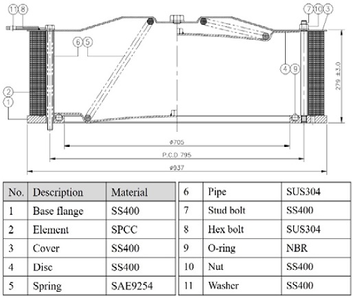
Figure 1 shows the structure of the developed ERV, which is composed of a cover, spring, disk, flange, and flame arrester. The ERV induces flames from an explosion in the crankcase and prevents flames from escaping the crankcase by quenching the temperature as it passes through the flame arrester [12]. The relief pressure is set using a spring between the cover and the disc. This spring is a cone spring that meets the cover and disk [6].
PROSAVE developed an ERV that could reduce production costs by 30%. Table 1 lists the specifications of the developed ERV. The company reduced the price of parts by reducing the width of the flame arrester compared to other products and changed the shape from horizontal to vertical. For cost reduction, the most significant change was made in the thickness of the flame trap. The thickness was reduced from 1.0 mm to 0.6 mm. The element width was reduced from 80 mm to 47 mm, and the diameter of the flange and cover was reduced from 987 to 930 mm. The weight decreased from 220 to 200 kgf.
3. Structure Analysis of ERV
3.1 Modeling and analysis conditions
The thickness of the developed ERV trap was reduced from 1.0 mm to 0.6 mm to save costs, and structural analysis was performed by modeling this in the same way as the actual shape. To compare the developed ERV with the conventional ERV, the variables were set as trap thicknesses of 1.0 mm and 0.6 mm and performed structural analysis. The trap was one body and was wound in four layers in a cylindrical shape. The results of the four layers of traps were compared based on the position on the same straight line. For structural analysis, the finite element analysis code Ansys Mechanical 2020 R1 was used, and the results of radial displacement and von Mises stress analysis were compared.
Figure 2 shows the shape of the ERV for structural analysis, in which the model was simplified by excluding the components that did not affect the analysis results. The size of the trap hole and the gap of each wound layer were the same in the 1.0 mm and 0.6 mm models and were modeled in the same shape as the model in which the explosion test was conducted.
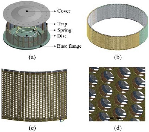
ERV structural analysis modeling for (a) Entire structure, (b) Entire trap structure, (c) Enlarged shape of 4-layer trap structure, (d) Trap structure mesh
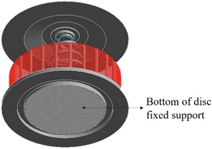
Because the bottom of the ERV base flange is attached and fixed to the engine, all six degrees of freedom of the base flange bottom were restrained and fixed, as shown in Figure 3.
Table 2 lists the material property values for each part used in the structural analysis. In terms of the material properties, SAE9254, SPCC, and mild steel were applied to spring, trap, and other components, respectively.
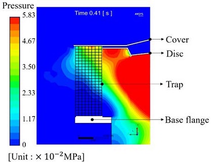
In terms of the loading conditions, the pressure calculated through the explosion analysis was used. Figure 4 shows the pressure distribution during the early stage of the ERV explosion. The pressure applied to the ERV differed according to the trap layer. In terms of defining the innermost layer as the first layer, the maximum pressures applied to the first to fourth layers are 0.0295, 0.0286, 0.0277, and 0.0268 MPa, respectively. For the temperature, 300 °C was applied by referring to the test results.
3.2 Radial displacement results
The radial displacement of the trap was calculated according to the temperature and pressure during the relief valve explosion. Although there are no criteria for allowable values of displacement, the goal was to develop an ERV that does not cause a displacement of more than 20% based on the spacing between each layer.
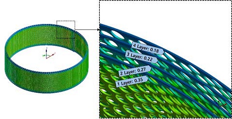
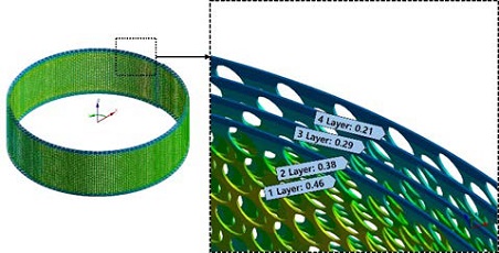
Figure 5 shows the radial displacement of each layer when the trap thickness is 1.0 mm. The largest displacement (0.35 mm) appeared at the inner-most layer, and the displacements decreased toward the outer layers. The displacement of the conventional ERV was up to 13.8% based on the spacing between each layer.
Figure 6 shows the radial displacement and radial displacement of each layer when the trap thickness is 0.6 mm. The largest displacement (0.46 mm) appeared at the innermost layer, and the displacements decreased toward the outer layers. The displacement of the developed ERV was up to 18.1%, based on the spacing between each layer. This satisfies the goal of developing a product with less than 20% spacing between the layers.
3.3 Von Mises stress results
The von Mises stress applied to the trap was calculated as the pressure and temperature increased owing to an explosion in the ERV. The material of the trap was SPCC, the yield stress was 170 MPa, and the tensile strength was 270 MPa; therefore, plastic strain occurred at a stress of 170–270 MPa, and the trap was damaged if the stress was over 270 MPa.
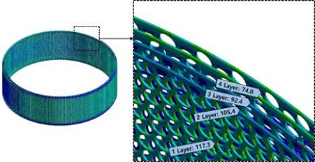
Figure 7 shows the von Mises stress when the trap thickness is 1 mm. The maximum stress (117.3 MPa) appeared in the innermost layer, and the stress decreased toward the outer layers. The maximum stress was equivalent to 69.0% of the allowable stress (yield stress); therefore, the trap will not be damaged in the event of an explosion.
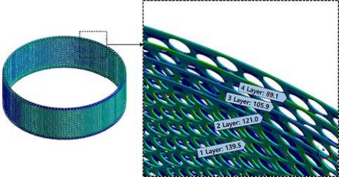
Figure 8 shows the von Mises stress when the trap thickness is 0.6 mm. The maximum stress (139.5 MPa) occurred in the innermost layer, and the stress decreased toward the outer layers. The maximum stress was equivalent to 82.1% of the allowable stress, so the trap would not be damaged in the event of an explosion.
Table 3 compares the structural analysis results when the trap thickness is 1.0 mm and 0.6 mm. Although the displacement and stress were higher at 0.6 mm than at 1.0 mm, the maximum stress of the 0.6 mm trap is still less than the yield stress of the material (170 MPa), so the trap will not be damaged in the event of an ERV explosion.
4. Method of explosion test
Many organizations have explosion test equipment for relief valves, but only a limited number can test ERVs according to the regulations. The explosion test of this study was performed by FYZIKÁLNĚ TECHNICKÝ ZKUŠEBNÍ ÚSTAV (FTZU) in the Czech Republic, which is an institute approved by MAN Energy Solutions.
Table 4 lists the parameters of the explosion tests. The capacity of the pressure vessel is determined by the size of the ERV, according to the IACS UR M66. The capacity of the pressure vessel used in the explosion test was 10 m3, which is the largest capacity for pressure vessels in the ERV explosion tests.
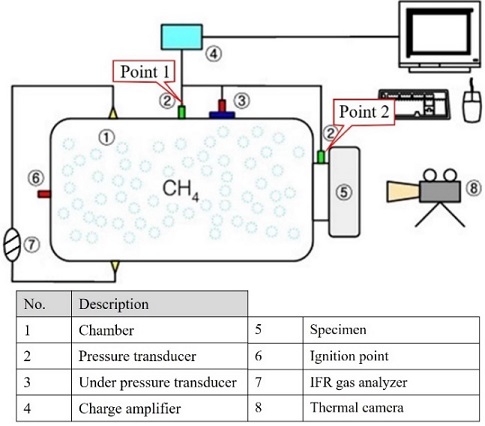
Figure 9 shows the configuration of the explosion test apparatus. The pressure vessel was filled with a methane-air mixture of 9.5 vol% methane, and the explosion inside the pressure vessel was caused by ignition with an energy of 100 J or less on the opposite side of the ERV.
In all explosion tests, the pressure was measured at the same two positions: Point 1 was the center of the pressure vessel and Point 2 was the neck of the ERV.
Two types of pressure transducers were used, depending on the pressure. The 701A piezoelectric pressure transducer from Kistler was used for pressures above atmospheric pressure. An under-pressure transducer and data logger Almemo2950 was used for vacuum pressure. The vacuum pressure was measured to confirm whether the valve was shut off and kept tight after the explosion. The methane concentration was measured using an infrared gas analyzer (Nicolet Avatar FT IR 32).
In terms of the methane concentration, a 9.5 ±0.5 vol% methane-air mixture was used for the explosion test. The maximum explosion pressure (8.61 bar) occurred when the concentration of methane was 9.6% [13].
The explosion test was performed in two stages in accordance with IACS US M66 (Rev. 3 Jan. 2008), which is required by MAN Energy Solutions [14]. The first stage was a foil test, where a 0.05 mm thick polyethylene film was installed in the place where the ERV should be installed, and then ignited to measure the explosion pressure inside the chamber. The purpose of the foil test is to establish a reference pressure to determine the performance of the ERV when the pressure rises in the pressure vessel. The performance of the ERV was evaluated by comparing the difference between the reference pressure determined in the foil test and the pressure from the following explosion test. The difference between the reference pressure and the maximum pressure of the explosion test is regulated to be within 1.4 barg to minimize the engine damage when an explosion occurs in the crankcase.
The second stage consisted of two explosion tests after the installation of the ERV. The first explosion test was carried out by wrapping a 0.05 mm thick polyethylene bag around the ERV before installing it for the test. The purpose of the polyethylene bag was to confirm whether the flame arrester prevented flames from escaping. During the experiment, the ERV opened and some unburned methane-air mixture remained in the polyethylene bag. If flames escape through the flame arrester, the unburned methane-air mixture remaining in the polyethylene bag will ignite.
The 2nd explosion test was performed without a polyethylene bag. The average temperature outside the flame arrester must remain below 220 °C after the explosion, and the ERV must operate normally after the 2nd explosion test.
After each explosion test, the test container was kept closed for at least 10 s to ensure the robustness of the ERV. The robustness of the ERV was confirmed by measuring the vacuum pressure after the explosion test.
5. Results of explosion test
Explosion tests need to be conducted on the ERV to check whether it meets the regulations and the results need to be analyzed based on the regulations proposed by the IACS and engine manufacturer. In the test procedure, after performing the foil test, two explosion tests were performed to check the pressure and vacuum pressure and were observed with a thermal imaging camera to check whether the flame was leaking.
5.1 Foil test
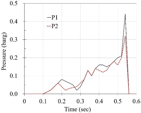
Figure 10 shows the explosion pressure over time in the foil test. The maximum pressure occurred 0.5 sec after ignition and was 0.44 barg at Point 1 and 0.32 barg at Point 2. Although the maximum pressure appeared at the same time, the pressure at Point 2 was less because the diameter of the neck was smaller than the diameter of the pressure vessel. This study set 0.44 barg (Point 1) as the reference pressure and compared it with the results of the explosion test.
5.2 First explosion test
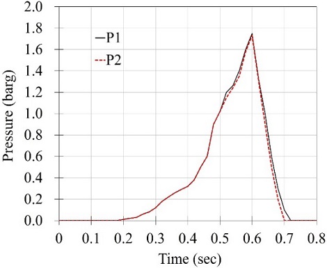
Figure 11 shows the explosion pressure results of the first explosion test. The maximum explosion pressure was 1.75 barg at Point 1 and 1.73 barg at Point 2.
In terms of comparing the results of the first explosion test with the foil test, there was a pressure difference of 1.31 barg. Because MAN Energy Solutions regulations require a pressure difference of less than 1.40 barg, the results satisfy the regulations with a margin of 0.09 barg. The pressure difference between Point 1 and Point 2 was not significant compared to the foil test because of the installation of the ERV.
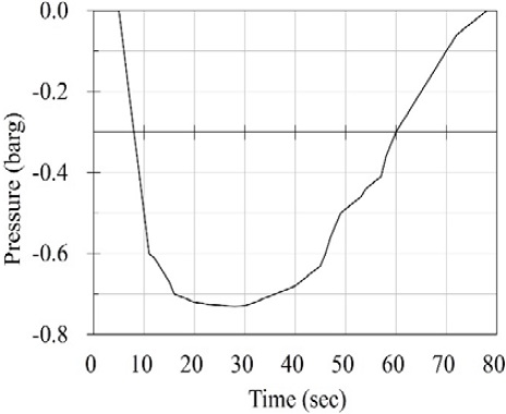
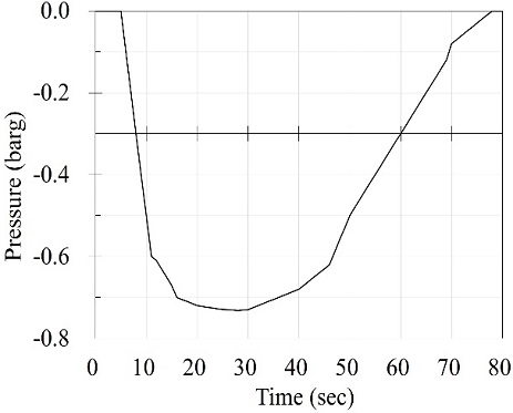
Figure 12 shows the pressure after the explosion. The maximum vacuum pressure was -0.731 barg. In addition, it was confirmed that the pressure was maintained below -0.3 barg for 50 sec, and a secondary explosion was prevented by maintaining a closed state after the explosion.
5.3 Second explosion test
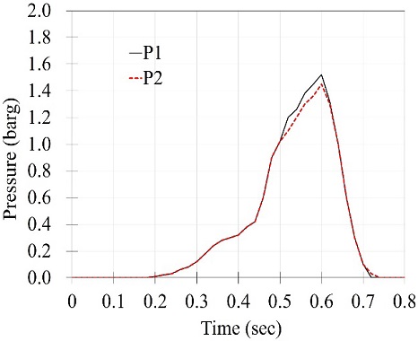
Figure 13 shows the explosion pressure results of the second explosion test. The maximum explosion pressure was 1.52 barg at Points 1 and 1.45 barg at Point 2.
Comparing the results of the second explosion test with the foil test, there was a pressure difference of 1.08 barg. Since the MAN Energy Solutions regulations require a pressure difference of less than 1.40 barg, the results satisfy the regulations with a margin of 0.32 barg. The pressure difference between Point 1 and Point 2 was not significant compared to the foil test because of the installation of the ERV.
Figure 14 shows the pressure after the explosion. The pressure was maintained below -0.3 barg for more than 10 sec, and the maximum vacuum pressure was -0.732 barg. In addition, it was confirmed that the pressure was maintained below -0.3 barg for 50 sec, and a secondary explosion was prevented by maintaining a closed state after the primary explosion.
5.4 External temperature of flame arrester
MAN Energy Solutions require the external temperature of the flame arrester to be kept below 220 °C one min after the explosion [14].
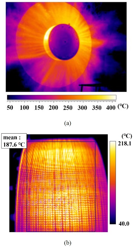
Figure 15 shows a photo of the external temperature of the ERV in the second explosion test using a thermal imaging camera. Flames did not erupt during the explosion test, and the highest temperature was observed in the flame arrester. The external temperature of the flame arrester reached up to 187.6 °C, and the average temperature during the explosion test was kept below 220 °C, as required by MAN Energy Solutions.
TheMAN Energy Solutions and IACS also recommend changing the ERV when an explosion occurs inside the crankcase [7]. As a result of the open up inspection of the ERV after the explosion test to verify the reliability, there was no damage to the components.
6. Conclusions
In this study, an ERV with a 0.6 mm thick trap was developed to reduce the cost of the ERV for the crankcase. The results of the structural analysis and performance tests are as follows.
- (1) According to the structural analysis of the developed ERV, the maximum radial displacement of the trap was 18.1% at the first layer and the maximum von Mises stress was 139.5 MPa at the first layer. These values were within the allowable range where the trap was not damaged by the explosion.
- (2) The maximum pressure in the foil test was 0.44 barg, and the explosion pressure was 1.75 barg in the first experiment and 1.52 barg in the second experiment, which satisfies the IACS reference value.
- (3) The external temperature of the flame arrester reached up to 187.6 °C and met the MAN Energy Solutions requirements.
- (4) The production cost was reduced by 30% by restructuring the ERV.
Based on the results of the structural analysis, the flow analysis in a follow-up study will analyze the porous passing through the flame arrest when an explosion occurs and use it to develop an ERV suitable for flow characteristics.
Author Contributions
Conceptualization, J. H. Kim and K. J. Kong; Methodology, J. H. Kim; Software, S. W. Kang; Validation, K. J. Kong; Investigation, J. H. Kim and K. J. Kong; Resources, J. H. Kim; Data Curation, S. W. Kang; Writing—Original Draft Preparation, J. H. Kim; Writing—Review & Editing, K. J. Kong; Supervision, K. J. Kong.
References
-
K. Cicek and M. Celik, “Application of failure modes and effects analysis to main engine crankcase explosion failure on-board ship,” Safety Science, vol. 51, no. 1, pp. 6-10, 2013.
[https://doi.org/10.1016/j.ssci.2012.06.003]

-
H. S. Yang, H. S. Park, J. H. Park, J. W. Eun, and Y. H. Lee, “Study of propane gas explosion experiment and numerical analysis of flame arrestor design for LPG ship exhaust system,” Journal of Advanced Marine Engineering and Technology, vol. 44, no. 1, pp. 34-41, 2020.
[https://doi.org/10.5916/jamet.2020.44.1.34]

-
K. P. Kim, Y. T. Kim, and H. K. Kang, “CFD approach on gas explosion for SIL in gas fuelled ship,” Journal of the Korean Society of Marine Engineering, vol. 39, no. 2, pp. 195-200, 2015.
[https://doi.org/10.5916/jkosme.2015.39.2.195]

-
S. M. Kang and B. H. Lee, “A numerical study on the flow characteristics through an industrial safety relief valve,” Journal of the Korean Society of Marine Engineering, vol. 33, no. 5, pp. 696-704, 2009 (in Korean).
[https://doi.org/10.5916/jkosme.2009.33.5.696]

-
L. Jiang, S. Zhang, X. Shu, W. Hao, Y. Ren, and Z. Chen, “Innovative design of Leeward surface of pin fin in flame arresters fitted in explosion relief valve,” International Conference on Mechanical Design 2019, vol. 77, pp. 274-287, 2020.
[https://doi.org/10.1007/978-981-32-9941-2_24]

-
H. R. Lee, J. H. Ahn, B. H. Ahn, and H. Y. Kim, “Design and evaluation of a crankcase relief valve spring for LNG-fueled ships,” Journal of The Korean Society of Manufacturing Technology Engineers, vol. 24, no. 3, pp. 263-269, 2015 (in Korean).
[https://doi.org/10.7735/ksmte.2015.24.3.263]

- IACS, Crankcase explosion relief valves for crankcases of internal combustion engines, UR M9, rev.3, corr.2, International Association of Classification Societies, England, 2007.
- IACS, Type testing procedure for crankcase explosion relief valves, UR M66, rev.3, International Association of Classification Societies, England, 2008.
- MAN Diesel, Crankcase relief valve prevention and damage control, SL09-512/CAA, MAN Diesel, Denmark, 2009.
- PROSAVE Co., LTD, “Explosion relief valve,” Korea, KR Patent 10-1800799, Nov. 17, 2017.
-
J. H. Kim, K. J. Kong, and T. Y. Jeong, “Performance test of crankcase explosion relief valve for large ship diesel engines,” The Journal of Fisheries and Marine Sciences Education, vol. 31, no. 5, pp. 1380-1386, 2019 (in Korean).
[https://doi.org/10.13000/JFMSE.2019.10.31.5.1380]

-
L. F. Jiang, H. Liu, and H. Liang, “Optimization of flame arrester structure of explosion-proof valve with flame arrester for diesel engine,” Applied Mechanics and Materials, vol. 511-512, pp. 595-598, 2014.
[https://doi.org/10.4028/www.scientific.net/AMM.511-512.595]

- O. S. Han, I. S. Han and Y. R. Choi, “Study on damage prediction in explosion accidents of chemical materials (Focused on Flammable gas),” Occupational Safety and Health Research Institute, pp. 18-21, 2015.
- MAN Diesel & Turbo, Crankcase explosion relief valve, first-time production approval, 0724839-2.6, MAN Diesel & Turbo, Germany, 2015.

