A study on the pressure gradient characteristics inside tube in shell-and-tube heat exchanger
Copyright © The Korean Society of Marine Engineering
This is an Open Access article distributed under the terms of the Creative Commons Attribution Non-Commercial License (http://creativecommons.org/licenses/by-nc/3.0), which permits unrestricted non-commercial use, distribution, and reproduction in any medium, provided the original work is properly cited.
Abstract
This study investigates the pressure gradient characteristics of the evaporator, a shell and tube-type heat exchanger used as a major component of the organic Rankine cycle, where the cooling water from the main engine's jacket is used as a heat source and the cold heat generated by the vaporizing LNG as a heat sink. At vapor qualities above 0.5, the two-phase frictional pressure drop correlations of Friedel and Muller-Steinhagen and Heck demonstrated almost similar values, unlike other correlations. However, at vapor qualities less than 0.5, the correlation of Muller-Steinhagen and Heck increased linearly between the homogenous flow model and Friedel correlation. The two-phase pressure gradient caused by acceleration was considerably lower, corresponding to approximately 1–9% of the frictional pressure gradient, and the two-phase frictional pressure drop accounted for most of the total pressure drop.
Keywords:
Heat exchanger, Multiplier, Organic Rankine cycle, Pressure gradient, Shell and tube1. Introduction
Accurate prediction of two-phase pressure drops in shell-and-tube heat exchanger-type evaporators and condensers and two-phase transport systems is essential in the design and optimization of refrigeration, air conditioning, and heat pump systems. Examples of evaporators include direct-expansion and flooded evaporators. In the case of direct-expansion evaporators, the use of an optimal two-phase pressure drop correlation is an important factor in designing the heat exchanger to maximize the flow boiling heat transfer performance. Numerous experimental studies and empirical prediction methods for the two-phase pressure drop, which should be considered first when designing a heat exchanger, have been conducted for the two-phase flow in the tube, resulting in the development of several empirical equations for the two-phase pressure drop in the tube.
In general, two components are considered for predicting the pressure drop because of a two-phase flow in a horizontal tube: the frictional pressure drop occurring on the wall surface of the flow channel and the pressure drop caused by the change in the kinetic energy of the fluid, with the former component being the most important and difficult to predict.
The homogeneous flow model is a convenient concept, which follows the existing design equation for single-phase fluids, assumes a similar fluid characterized by appropriate average properties of the liquid and vapor phases, and also that there is no difference in velocity between the two phases. The separated flow model assumes that the flow in the pipe is artificially separated into two flows: a liquid phase and a vapor phase. In this case, it is assumed that although the two phases are constant, they do not necessarily have to flow at the same speed.
Beattie and Whalley [1] proposed a homogeneous flow model that considers the influence of flow patterns. They derived a two-phase viscous model based on the flow patterns of a bubble and annular flow. Their viscous model was more suitable for gravity-dominated flows, such as bubble flow in conventional horizontal or vertical tubes.
Lockhart and Martinelli [2] first proposed a separated flow model and predicted the two-phase flow pressure drop by multiplying the friction pressure drop in a single phase by a two-phase multiplier, which was provided as a function of the Martinelli parameter. Friedel [3] assumed the two-phase friction multiplier as a function of the Froude number, Weber number, vapor quality, and thermodynamic properties. Muller-Steinhagen and Heck [4] proposed a two-phase frictional pressure gradient correlation, an empirical interpolation of all liquid and vapor flows.
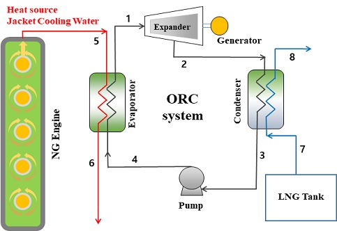
In this study, an organic Rankine cycle (ORC) system [5] was constructed. In ORC, the high-temperature heat source uses the coolant from the jacket of the main engine of the LNG-fueled ship, and the low-temperature heat sink uses the cold heat generated by the vaporization of LNG. To examine the pressure drop characteristics of the evaporator, which is a shell-and-tube heat exchanger and among the main components of ORC, we compared and analyzed the existing pressure drop correlations.
2. ORC System and Heat Exchanger
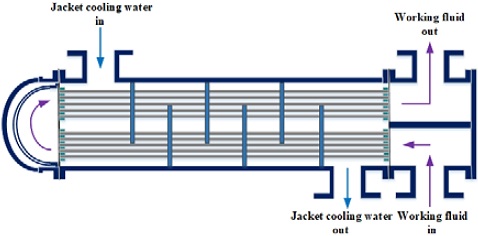
The ORC proposed in a previous study [5] used the cold heat generated by the vaporizing LNG in LNG-fueled ships with a low-temperature heat sink and coolant from the jacket of the main engine with a high-temperature heat source, as shown in Figure 1. In this study, the characteristics of the pressure drop in the evaporator, which is among the elements that constitute the ORC system, were investigated. Figure 2 shows the shell-and-tube heat exchanger corresponding to the evaporator.
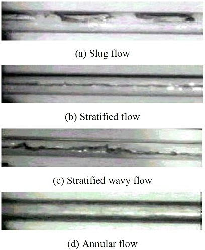
The jacket cooling water transfers heat to the working fluid flowing in the tube while flowing through the shell side. As the working fluid supplied with energy flows through the tube, a phase change occurs from liquid to vapor. The flow phenomenon in the tube is shown in Figure 3 [6]. Bubbles begin generating in the liquid working fluid near the tube inlet, and their diameter gradually increases, subsequently turning the liquid into a slug flow, which is a mass of bubbles. As the vapor quality increases, the flow pattern changes into a stratified flow, and is divided into vapor and liquid phases at the top and bottom of the tube section, respectively. With a further increase in vapor quality, it changes into a stratified wavy flow with waves forming in the boundary layer. When the vapor quality reaches approximately 0.2, it changes into an annular flow, where the vapor is distributed in the center of the tube and the liquid flows around the outer circumference of the tube. When the vapor quality exceeds approximately 0.8, the liquid almost evaporates and changes into a spray flow in the form of droplets.
Figure 4 shows the different flow patterns [7]. In this study, R134a refrigerant was used as the working fluid, and its properties were calculated using REFPROP 9.1. Table 1 lists the initial values of the evaporator.
3. Pressure Drop Correlations
3.1 Total Pressure Drop
The total pressure drop during a two-phase flow in a pipe can be expressed as follows [8]:
| (1) |
Here ΔPf,TP denotes the two-phase friction pressure drop and ΔPa,TP denotes the pressure drop because of acceleration, and can be expressed by the following equation by Martinelli-Nelson [9].
| (2) |
Here, α is the void fraction, which can be expressed in terms of vapor quality using the correlation of Zivi [10].
| (3) |
3.2 Homogenous Flow Model
The homogeneous flow model assumes a two-phase mixture where the liquid and vapor phases have the same velocity. The properties of the mixture are calculated using the quality and properties of the liquid and vapor. The two-phase friction pressure drop based on the homogeneous flow model is expressed as follows:
| (4) |
The friction factor can be expressed in terms of the Reynolds number using the Blasius equation.
In Equation (4), the two-phase density is expressed as the quality and density of the liquid and vapor.
The two-phase friction pressure drop can vary depending on the various mixture viscosity models used to calculate the two-phase Reynolds number, which is defined as follows:
| (5) |
Among the several viscous models, the two-phase mixture viscosity model proposed by McAdams [11] is defined as follows:
| (6) |
3.3 Separated Flow Model
The segregated flow model was first introduced by Lockhart and Martinelli [2] by assuming a difference between the velocities of the liquid and vapor phases. The two-phase friction pressure drop was calculated by multiplying the single-phase friction pressure drop by the two-phase friction multiplier, as follows:
| (7) |
The two-phase friction multiplier used in the above equation was derived by Chisholm [12] as:
| (8) |
Here, C has a different value depending on whether the flow of the liquid and vapor phases is laminar or turbulent, and the Martinelli variable is defined as follows:
| (9) |
Friedel [3] obtained the following equation by optimizing for a two-phase friction multiplier, assuming an entirely liquid-based flow, based on 25,000 data.
| (10) |
The value of A in the above equation is obtained as follows:
The two-phase Froude number and Weber number are calculated as follows:
Muller-Steinhagen and Heck [4] obtained good results by comparing their developed correlations with the 14 existing correlations, based on 9,300 data obtained from water-steam, air-water, air-oil, and various refrigerants.
| (11) |
Here, the coefficient G is as obtained as follows:
Coefficients A and B are the friction pressure gradients for a completely liquid and completely vapor flow, respectively.
Jung and Radermacher [13] developed a two-phase friction multiplier as a function of the Martinelli parameter and vapor quality for several refrigerants.
| (12) |
Lim [7] defined the two-phase friction multiplier as a function of the Martinelli parameter, two-phase Froude number, and Weber number as follows:
| (13) |
Here, the coefficient A is defined as follows:
4. Results and Discussion
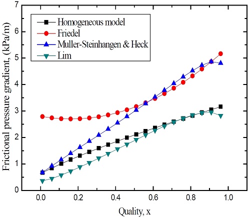
Figure 5 shows the variations in the two-phase friction pressure gradient according to the changes in vapor quality. Most of the correlations show an increasing tendency with the increasing vapor quality. Because the Lockhart and Martinelli correlation predicts a significantly high two-phase frictional pressure gradient, and that of Jung is also higher than that predicted by other correlations, these two have been omitted from this graph. Lim's correlation shows the lowest prediction, followed by the homogeneous flow model. The Friedel correlation shows the highest prediction when the vapor quality is 0.5 or lower. It is evident that the correlation by Muller-Steinhagen and Heck shows a linear increase between the homogeneous flow model and the-Friedel correlation when the vapor quality is lower than 0.5. However, as the quality increases, the correlation of Muller-Steinhagen and Heck is slightly higher than that of the Friedel correlation. Friedel's correlation is known to satisfactorily predict the two-phase frictional pressure gradients. Therefore, it may be considered that the prediction results of Friedel’s and Muller-Steinhagen and Heck’s correlations are valid when the quality is higher than 0.5, but further review is needed for quality 0.5 or lower.
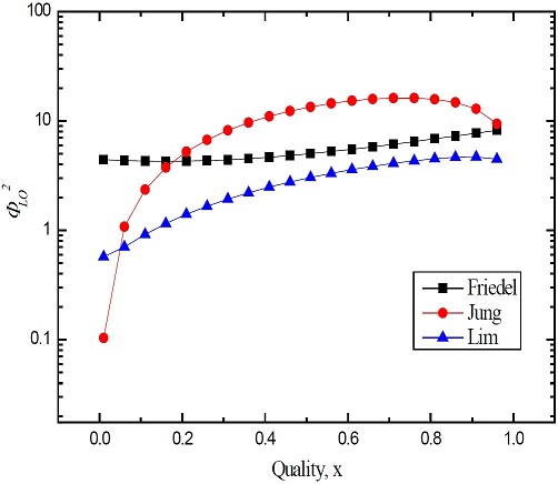
Figure 6 shows the variations in the two-phase friction multiplier with increasing vapor quality. Jung's two-phase friction multiplier is predicted to be the highest, except in the low-quality region. Therefore, the two-phase frictional pressure gradient is also highly predicted. Lim's two-phase friction multiplier is predicted to be the lowest. As a result, the two-phase friction pressure gradient is also predicted to be low. Friedel's correlation increases almost linearly between the two-phase friction multipliers of Jung and Lim, except in the low-quality region.
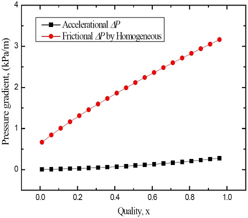
Figure 7 shows the variations in the two-phase pressure gradient because of acceleration and the friction pressure gradient predicted from the homogeneous flow model. One can observe that although the two-phase pressure gradient caused by acceleration gradually increases with the increasing vapor quality, its value is considerably small compared to the friction pressure gradient. In other words, the two-phase pressure gradient caused by acceleration corresponds to approximately 1–9% of the friction pressure gradient.
5. Conclusion
In this study, the characteristics of the pressure drop in the tube of the evaporator, among the several heat exchangers constituting the ORC system, were investigated, and the following conclusions were obtained.
- 1. The two-phase frictional pressure gradient increases with increasing vapor quality, and the Muller-Steinhagen and Heck’s correlation shows a linear increase between those of the homogeneous flow model and Friedel. If the vapor quality is greater than 0.5, the predictions of Friedel's and Muller-Steinhagen and Heck's correlations are considered to be accurate.
- 2. The variation in Friedel's two-phase friction multiplier was found to increase almost linearly between those of Jung and Lim, except in the low-quality region.
The two-phase pressure gradient caused by acceleration exhibits a considerably low value, corresponding to approximately 1– 9% of the friction pressure gradient.
Nomenclature
| d : | Diameter [m] |
| f : | Friction factor |
| g : | Acceleration due to gravity [m/s2] |
| G : | Mass velocity [kg/m2s] |
| Fr : | Liquid Froude number |
| P : | Pressure drop [Pa] |
| Re : | Reynolds number |
| x : | Vapor quality |
| X : | Martinelli parameter |
| We : | Weber number |
Greek symbols
| μ : | Viscosity [Pa•s] |
| ρ : | Density [kg/m3] |
| σ : | Surface tension [N/m] |
| Ф : | Two-phase frictional multiplier |
Subscripts
| a : | Acceleration |
| f : | Fluid |
| fo : | Total flow assumed as liquid |
| fo : | Total flow assumed as liquid |
| g : | Gas |
| TP : | Two phase |
Acknowledgments
This research was supported by the project “Test evaluation for LNG bunkering equipment and development of test technology (Grant No. 20180048)” funded by the Ministry of Oceans and Fisheries.
Author Contributions
Conceptualization, T. W. Lim and H. K. Kang; Methodology, T. W. Lim and H. K. Kang; Software, T. W. Lim; Validation, T. W. Lim and H. K. Kang; Formal Analysis, T. W. Lim; Investigation, T. W. Lim and H. K. Kang; Resources, H. K. Kang; Data Curation, T. W. Lim; Writing—Original Draft Preparation, T. W. Lim; Writing—Review & Editing, T. W. Lim and H. K. Kang; Visualization, T. W. Lim; Supervision, T. W. Lim; Project Administration, H. K. Kang; Funding Acquisition, H. K. Kang.
References
-
D. R. H. Beattie and P. B. Whalley, “A simple two-phase frictional pressure drop calculation method,” International Journal of Multiphase Flow, vol. 8, no. 1, pp. 83-87, 1982.
[https://doi.org/10.1016/0301-9322(82)90009-X]

- R. W. Lockhar and R. C. Martinelli, “Proposed correlation of data for isothermal two-phase, two-component flow in pipes,” Chemical Engineering Progress, vol. 45, pp. 39-48, 1949.
- L. Friedel, “Improved friction pressure drop correlation for horizontal and vertical two-phase pipe flow,” Proceeding of European Two-phase Group Meeting, 1979.
-
H. Müller-Steinhagen and K. Heck, “A simple friction pressure drop correlation for two-phase flow in pipes,” Chemical Engineering Processing: Process Intensification, vol. 20, no. 6, pp. 297-308, 1986.
[https://doi.org/10.1016/0255-2701(86)80008-3]

-
Y. S. Choi, Y. H. Lee, H. K. Kang and T. W. Lim, Performance analysis of the organic Rankine cycle using LNG cold ernegy in LNG-fueled ships, Journal of the Korean Society of Marine Engineering 42(7), pp. 524∼530, 2018.
[https://doi.org/10.5916/jkosme.2018.42.7.524]

- F. P. Incropera and D. P. DeWitt, Fundamentals of Heat and Mass Transfer, 5th edition, New York, USA: John Wiley & Sons, 2002.
-
T. W. Lim and J. H. Kim, “An experiment investigation of pressure drop in flow boiling of pure refrigerants and their mixture in horizontal tube,” JSME International Journal, vol. 48, no. 1, pp. 92-98, 2005.
[https://doi.org/10.1299/jsmeb.48.92]

-
T. W. Lim, S. -S. You, and H. -S. Kim, “Two-phase pressure drop in horizontal ractangular channel,” Journal of Fisheries and Marine Sciences Education, vol. 25, no. 3, pp. 625-631, 2013 (in Korean).
[https://doi.org/10.13000/JFMSE.2013.25.3.625]

- R. C. Martinelli and D. B. Nelson, “Prediction of pressure drop during forced-circulation boiling water,” Transaction of the ASME, vol. 70, pp. 695-702, 1948.
-
S. M. Zivi, “Estimation of steady-state steam void fraction by means of the principle of minimum entropy production,” Journal of Heat Transfer, vol. 86, no. 2, pp. 247-251, 1964.
[https://doi.org/10.1115/1.3687113]

- W. H. McAdams, W. K. Woods, and L. C. Heroman, “Vaporization inside horizontal tubes-II, Benzene–oil mixture,” Transaction of the ASME, vol. 64, pp. 193-200, 1942.
-
D. Chisholm, “A theoretical basis for the Lockhart-Martinelli correlation for two-phase flow,” International Journal of Heat and Mass Transfer, vol. 10, no. 12, pp. 1767-1778, 1967.
[https://doi.org/10.1016/0017-9310(67)90047-6]

-
D. S. Jung and R. Radermacher, “Prediction of pressure drop during horizontal annular flow boiling of pure and mixed refrigerants,” International Journal of Heat and Mass Transfer, vol. 32, no. 12, pp. 2435-2446, 1989.
[https://doi.org/10.1016/0017-9310(89)90203-2]


