Heat transfer optimization in a vertical cylinder tube with vertically arranged fins
Copyright © The Korean Society of Marine Engineering
This is an Open Access article distributed under the terms of the Creative Commons Attribution Non-Commercial License (http://creativecommons.org/licenses/by-nc/3.0), which permits unrestricted non-commercial use, distribution, and reproduction in any medium, provided the original work is properly cited.
Abstract
The optimal geometric configuration of a passive heat exchanger in a vertical cylinder is presented herein. The heat exchanger is positioned vertically at the center of the cylinder. Several parameters and flow conditions are investigated to determine the optimized geometric parameters. The finite volume numerical technique is used to obtain computational results. The results show that the number of fins and the cylinder height impose a more significant effect as the inlet velocity increases, whereas the fin height shows similar effects for all inlet velocities tested (1 to 5 m/s). The best heat flux performance is observed at a fin height of 10 mm and a fin count of 58 at a high inlet velocity. A cylinder length of 200 mm is selected considering geometry restrictions.
Keywords:
Finite volume scheme, Forced convection, Heat sink, Channel flow1. Introduction
A plate-fin heat exchanger is a passive cooling system that has no external power to an active system. This type of heat exchanger offers a long lifespan, high reliability, and long suitability because it does not require additional equipment for an active system. Hence, it has been used for several decades.
Wang et al. [1] investigated plate-fin heat exchangers with plain fins and serrated fins. They performed numerical simulations to determine the heat transfer and fluid flow characteristics of heat exchangers with two fins. Grupta et al. [2] investigated a plate-fin heat exchanger with triangular fins. They demonstrated the flow structure and thermal performance of a winglet vortex generator for heat transfer enhancement. Zhu and Li [3] investigated flow and heat transfer characteristics by considering the effects of fin thickness and thermal effects on four types of fins. They presented the results for modified and conventional fin types. In addition, they provided the flow and thermal distribution of a plate-fin heat exchanger. Peng et al. [4] investigated fin geometry configurations as design parameters and integrated the design of a cross-plate-fin heat exchanger to optimize the total heat transfer area. Yousefi et al. [5] proposed a harmony search algorithm for design optimization to obtain the parameter variables. They suggested general optimization methodologies for a multistream plate-fin heat exchanger with fin selection and pressure drop considerations. In addition, they suggested an optimum design solution. Chen and Hsu [6] and Chen et al. [7] used the inverse, finite difference, and least-squares methods for their numerical simulation. In addition, they presented experimental data for predicting the fin efficiency and average heat transfer coefficient of a plate fin and tube heat exchanger with a single tube.
In this study, a plate-fin heat exchanger with a vertically arranged configuration was investigated. The system is used to cool air that is induced in hot ambient environments for a portable cooling system. Forced air flows from the top to the bottom of the system. The optimum geometry configuration of a plate-fin heat exchanger for achieving high heat dissipation performance was determined. Hence, several geometric configurations and flow conditions were investigated.
2. Mathematical Modeling
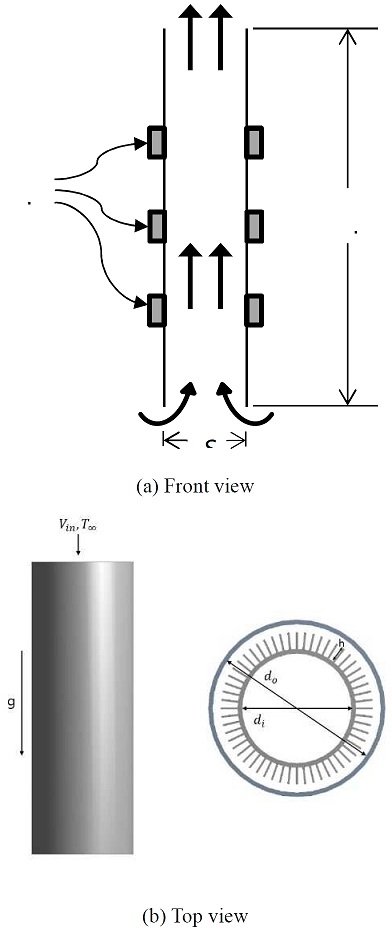
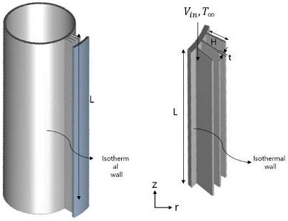
To obtain the optimized design parameters for a specified geometry, a three-dimensional numerical simulation was performed. A plate-fin heat exchanger located inside a vertical tube was modeled, as shown in Figure 1. Additionally, a fan was modeled at the top of the system. Therefore, the air flows from the top to the bottom. (Figure 1a). A plate-fin heat exchanger was attached to the outer surface of the inner cylinder. Under the assumption of a thin fin, the fins were vertically located along the circumferential direction. The inner cylinder was positioned inside the center of the outer cylinder. The geometric parameters are shown in Figure 1b. Figure 2 shows the computational domain, which is shown from the entire cylinder.
Considerable computational time is required when performing computational calculations for a three-dimensional geometry. As the geometry investigated is symmetrical along the circular direction, only a portion of the entire three-dimensional cylinder was selected for the computational domain. The domain shows only a section of the cooling air section, which is the main area of observation for the heat dissipation system. Both circular end areas of the cutting geometry had a symmetry boundary condition. The corresponding results were observed in this domain. After performing the computation, the results were recalculated considering the entire system.
The initial settings were as follows: The outer diameter of the outer cylinder was 120 mm, and the inner diameter of the inner pipe was 60 mm. The length and thickness of the fin was 10 and 1 mm, respectively. The vertical length of the cylinder was 200 mm. The attached fin count was 50 at the starting point.
The system was simulated under steady-state three-dimensional conditions in forced convection. Hence, the corresponding governing equations of continuity, momentum, and energy were used. The physical properties were assumed to be constant for all situations, including density. The k–model was used to incorporate turbulence effects. The governing equations are as follows [2]:
Continuity:
| (1) |
Momentum:
| (2) |
Energy:
| (3) |
where ρh is the density, μeis dynamic viscosity, p the pressure, kc the thermal conductivity, T the temperature, and α the thermal diffusivity; u, v, and w are the velocities in the x-, y-, and z-directions, respectively.
The Reynolds stress, must be modeled to complete the equation. For turbulence modeling, the standard khe model is typically used. The turbulence-related governing equations are as follows:
The turbulence kinetic energy equation:
| (4) |
The turbulence rate of dissipation equation:
| (5) |
where Gk is the generation of turbulent kinetic energy to the mean velocity gradients, and Gb represents the generation of turbulent kinetic energy.
The turbulent viscosity, μt, is expressed as follows:
| (6) |
where Cμ is a constant.
The model constants are as follows:
C1ε = 1.44; C2ε = 1.92; Cμ= 0.09; σk=1.0; σε = 1.3
To calculate the heat transfer performance, the average Nusselt number with a characteristic length L was evaluated based on the following equation:
where is the average heat transfer coefficient, L the cylinder length, and k the thermal conductivity.
The finite control volume method was used to calculate the numerical solution of the governing equations. The second-order upwind method was used for the convective and diffusive terms. The SIMPLER algorithm was used to solve the coupling between the velocity and pressure fields.
Based on an optimized mesh, fluid analysis for various boundary conditions was performed using ANSYS Fluent [8]. The mesh was densely distributed near the boundaries, which were positioned at highly variable gradients. Fluid flow can be analyzed by assigning constant inlet boundary conditions and an ambient pressure outlet. The temperature conditions of the cylinders were set as the first boundary condition. Both circular end sections of the cylinder were set as the second boundary condition.
3. Results and discussion
In this section, the computational results of a plate-fin heat exchanger in a forced convection cooling system are presented. The variables of the cooling system were selected to achieve good system performance. As mentioned previously, the parameters of the system were selected by performing numerical simulations. For grid independence, the test was conducted using various grid numbers (see Kim [9]). The geometry parameter and flow condition results are as follows:
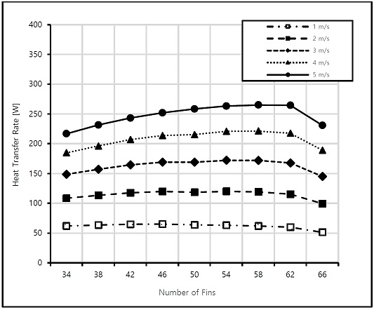
Figure 3 shows the heat transfer rate variation for different fin counts. The inlet velocities were varied from 1 to 5 m/s. For computation, the fin and cylinder heights were set to 10 and 200 mm, respectively, and the fin count was changed from 34 to 66. As shown in Figure 3, the heat transfer rates increased with the fin count. This increase continued up to 62 fin counts and then decreased. This is because as the fin count increased, the fin pitch decreased, and the heat transfer area increased. This implies that the flow simultaneously increased the pressure drop and heat transfer. At low inlet velocities, the heat transfer rate was insignificant as the inlet velocities increased. Beyond a 4 m/s inlet velocity, the heat transfer rate increased. Therefore, a fin count of approximately 58 and high inlet velocities provided a favorable heat transfer operation.
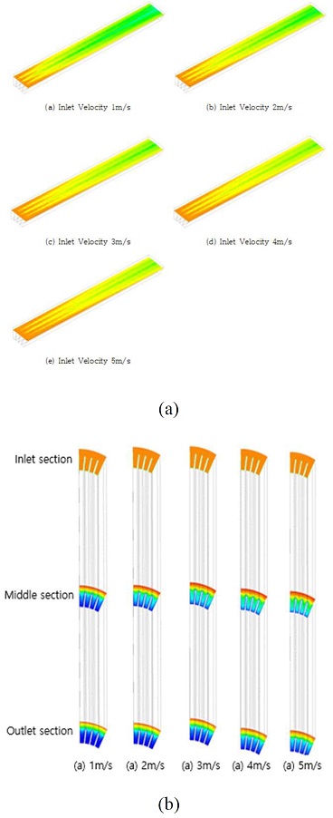
Figure 4a shows the temperature contours along the flow direction with the effects of inlet velocities. Cases involving high inlet velocity showed high-temperature transfers from the inlet section. At a high velocity, heat energy is transferred rapidly, as shown clearly in the comparison of temperature difference between the 1 and 5 m/s cases. Figure 4b shows the temperature contours at three different locations: the inlet, middle, and outlet sections. These figures are shown in the cutting section at the center of the cylinder. The inlet velocity changed from 1 to 5 m/s, as shown from the left to the right of the figure. The outlet temperature profile shows a clear temperature difference between the extreme cases.
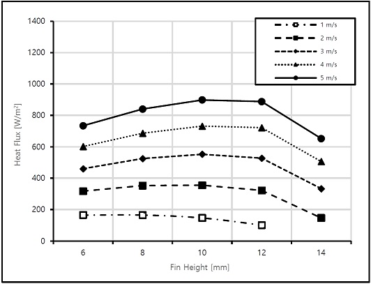
Figure 5 shows the heat flux variations for different fin heights. The fins were attached at the inner cylinder surface outwardly. The temperature boundary condition was set to a constant because of the high thermal conductivity of the fins. As shown in Figure 5, the heat flux variations increased with the fin height. When the fin height was 10 mm, the heat flux indicated good performance. Furthermore, the same pattern was exhibited at the high inlet velocities. Beyond 10 mm fin height, the heat transfer did not increase. However, at 14 mm fin height, the heat transfer decreased. Based on Figure 5, the best heat flux performance was demonstrated at 10 mm fin height along with high inlet velocities.
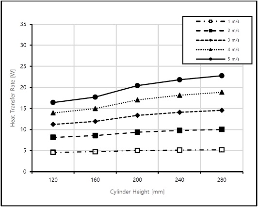
Figure 6 shows the heat flux variations for different cylinder heights that were positioned vertically. The cylinder height increased from 120 to 200 mm at every 40 mm interval. The cylinder height is a three-dimensional factor that is used to consider the total volume size of the system. As shown in Figure 6, the transfer rate increased insignificantly when the inlet velocity was low. However, beyond 3 m/s of inlet velocity, the heat transfer increased significantly compared with the previous increase. At 5 m/s, the heat transfer increased significantly with the increase in the cylinder height. As the cylinder height increased, the heat transfer area increased. A cylinder length of 200 mm was selected, considering the geometry restriction.
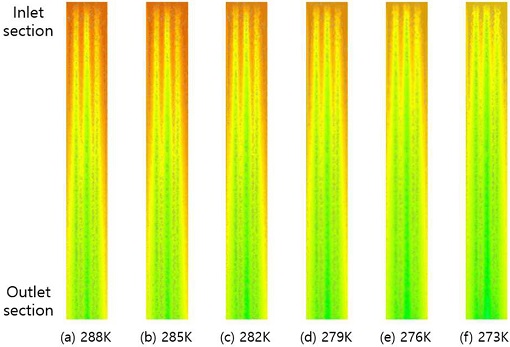
Figure 7 shows the temperature distribution of air based on the temperature change of the inner wall. The inner wall corresponded to the fin inside the cooler, and the temperature of the fin changed from 273 to 288 K. The external temperature was set to 303 K. The remaining geometry conditions were set as follows: length of fins, 10 mm; length of cylinder, 200 mm. The cooling boundary effects are clearly shown between the far-right and far-left figures.
Table 1 shows the net heat transfer rate when the temperature of the inner wall changed from 273 to 288 K. As shown in Table 1, the heat flux decreased as the temperature of the inner wall increased. When the temperature changed by 10°, the heat flow decreased by one-half. Therefore, to improve the thermal dissipation performance, the temperature of the inner wall surface must remain as low as possible.
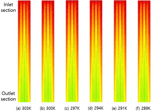
Figure 8 shows the temperature distribution of air with temperature changes on the external wall. The external temperature changed from 303 to 289 K. The temperature of the inner fins of the inner cylinder was set to 273 K. The remaining conditions were set as follows: number of fins, 50; length of fins, 10 mm; length of cylinder, 200 mm. Figure 8 shows the temperature difference contours between the two extreme cases.
Table 2 shows the net heat transfer rate when the temperature of the outer wall changed from 303 to 289 K. As shown in Table 2, the total heat flux decreased as the temperature of the exterior wall decreased linearly.
4. Conclusions
In this study, a plate-fin heat exchanger in a cooling system was investigated. A three-dimensional cylinder-type heat sink with vertical plates was successfully analyzed using the finite volume method. To obtain the optimal configurations, several parameters in a confined geometry were investigated.
At low inlet velocities, the heat transfer effect of the fin count was insignificant. However, a high inlet velocity of approximately 58 fins yielded favorable heat transfer. The best heat flux performance was indicated at a fin height of 10 mm along with high inlet velocities. At 5 m/s, the heat transfer increased significantly with the cylinder height. As the cylinder height increased, the heat transfer area increased. A cylinder length of 200 mm was selected considering the geometry restriction.
Nomenclature
| cp : | specific heat at constant pressure, J∙kg-1∙K-1 |
| din : | inner diameter of cylinder, mm |
| dout : | outer diameter of cylinder, mm |
| k : | thermal conductivity of fluid, K∙m-1∙K-1 |
| h : | height of fin, mm |
| L : | total length of cylinder, mm |
| Nu : | average Nusselt number |
| p : | pressure, N∙m-2 |
| T : | fluid temperature, K |
| V : | velocity |
| xi : | coordinate components, mm |
| vi : | velocity components, m∙s-1 |
Greek Symbols
| ε : | turbulent dissipation rate, m2∙s-3 |
| ρ : | density |
| μt : | viscous dissipation, m2∙s-3 |
| v : | dynamic viscosity, kg∙s-1∙m-1 |
Subscripts
| ∞ : | ambient |
| in : | inlet |
| out : | outlet |
Acknowledgments
This work was supported by a Research Grant of Pukyong National University (2019 year)
Author Contributions
Conceptualization, E. Kim; Methodology, E. Kim; Software, E. Kim; Formal Analysis, E. Kim; Investigation, E. Kim; Resources, E. Kim; Data Curation E. Kim; Writing-Original Draft Preparation, E. Kim; Writing-Review & Editing, E. Kim; Visualization, E. Kim; Supervision, E. Kim; Project Administration, E. Kim; Funding Acquisition, E. Kim.
References
-
Y. Q. Wang, Q. W. Dong, M. S. Liu, and D. Wang, “Numerical study on plate-fin heat exchangers with plain fins and serrated fins at low Reynolds number,” Chemical Engineering Technology, vol. 32, no. 8, pp. 1219-1226, 2009.
[https://doi.org/10.1002/ceat.200900079]

-
M. Gupta, K. S. Kasana, and R. Vasudevan, “A numerical study of the effect on flow structure and heat transfer of a rectangular winglet pair in a plate fin heat exchanger,” Journal of Mechanical Engineering Science, vol. 223, no. 9, pp. 2109-2215, 2009.
[https://doi.org/10.1243/09544062JMES1405]

-
Y. Zhu and Y. Li, “Three-dimensional numerical simulation on the Laminar flow and heat transfer in four basic fins of plate-fin heat exchangers,” Journal of Heat Transfer, vol. 130, no. 11, 2008.
[https://doi.org/10.1115/1.2970072]

-
H. Peng and X. Ling, “Optimal design approach for the plate-fin heat exchangers using neural networks cooperated with genetic algorithms,” Applied Thermal Engineering, vol. 28, no. 5-6, pp. 642-650, 2008.
[https://doi.org/10.1016/j.applthermaleng.2007.03.032]

-
M. Yousefi, R. Enayatifar, A. N. Darus, and A. H. Abdullah, “Optimization of plate-fin heat exchangers by an improved harmony search algorithm,” Applied Thermal Engineering, vol. 50, no. 1, pp. 877-885, 2013.
[https://doi.org/10.1016/j.applthermaleng.2012.05.038]

-
H. T. Chen and W. L. Hsu, “Estimation of heat transfer coefficient on the fin of annular-finned tube heat exchangers in natural convection for various fin spacings,” International Journal of Heat Mass Transfer, vol. 50, no. 9-10, pp. 1750-1761, 2007.
[https://doi.org/10.1016/j.ijheatmasstransfer.2006.10.021]

-
H. T. Chen, Y. S. Lin, P. C. Chen, and J. R. Chang, “Numerical and experimental study of natural convection heat transfer characteristics for vertical plate fin and tube heat exchangers with various tube diameters,” International Journal of Heat Mass Transfer, vol. 100, pp. 320-331, 2016.
[https://doi.org/10.1016/j.ijheatmasstransfer.2016.04.039]

- ANSYS Inc. Ver. 16, www.ansys.com, , Accessed November 21, 2020.
-
E. P. Kim, “Numerical analysis of a channel flow with two tubes in a vertical plain-fin type heat exchanger,” Journal of the Korean Society Marine Engineering, vol. 41, no. 5, pp. 383-388, 2017.
[https://doi.org/10.5916/jkosme.2017.41.5.383]


