A study on sensorless control of low-speed range for induction motors
 ; Young-Jae Kim2
 ; Kyoung-Kuk Yoon3
 ; Sae-Gin Oh4
 ; Jung-Ho Noh5
 ; Seong-Wan Kim5, 6
 ; Jong-Su Kim†
Copyright Ⓒ The Korean Society of Marine Engineering
This is an Open Access article distributed under the terms of the Creative Commons Attribution Non-Commercial License (http://creativecommons.org/licenses/by-nc/3.0), which permits unrestricted non-commercial use, distribution, and reproduction in any medium, provided the original work is properly cited.
Abstract
This study proposes a new control system by combining indirect vector control using a space vector modulation with sensorless speed control using an AFE rectifier and current error compensation. The AFE method can control the harmonics included in the input power by actively controlling the input current of the AC power, and a quality power source can be achieved by controlling the power factor of the input voltage and current. To verify the applicability of the proposed algorithm and system, the response characteristics of the indirect vector control using a modified space vector pulse width modulation with an AFE rectifier and a 2.2 [kW] induction motor were analyzed through computer simulations and real-world experiments. As the results indicate, an excellent input current is supplied, and the speed response and load characteristics of the induction motor are of high quality even within an extremely low-speed range.
Keywords:
Induction motor, Active front end, Sensorless, Space vector modulation, Low-speed range1. Introduction
Recently, various regulations have been strengthened to reduce the emission of environmental pollutants from ships, mainly by international maritime organizations in the maritime industry sector, and in response, electric propulsion vessels using ecofriendly energy are being developed. As a propulsion device of such electric propulsion vessels, induction motors are being applied.
A speed detector such as an encoder should be attached to the rotor to obtain the speed information. When an encoder is used in the induction motor control system, there is an advantage in that the speed and position of the rotor can be continuously detected; however, there are also major disadvantages in that the price of the entire system increases, the control algorithm is extremely complex, and an induction motor cannot be operated when a problem of the speed detection part occurs.
Therefore, sensorless control methods have been developed, which facilitate the emergency operation of an induction motor even when a system problem related to speed and position detectors occurs. These include methods for estimating the magnetic flux and rotor speed from the motor state equation by measuring the stator voltage and current values [16][17], a method for estimating the speed by applying the difference in the state estimates obtained from the stator model and the rotor model to the adaptive mechanism [1], and a method for obtaining the speed information by estimating the rotor flux with a monitoring device and using the current error of the stator and the magnetic flux of the rotor [2]. In addition, the following methods have been reported: the use of artificial intelligence circuits [3][4], application of a Kalman filter, which is an optimal filtering algorithm used when the inputs and outputs are affected by noise [5][6], speed estimation based on the estimated voltage of the stator or current harmonics caused by a reluctance change through the rotator slot [7], estimating the speed by detecting the voltage and current after injecting a high-frequency current [8], and using a state feedback linearization technique and current error compensation [9][10].
Most of the existing sensorless speed control methods can obtain relatively good control results within the high-speed range. However, it is difficult to expect good control results within the low-speed range. To improve this, the sensorless speed control topology of the induction motor by the current error compensation proposed in this study employs a proportional-integral (PI) controller for an electric current response within a broad range of speed and applies a modified spatial vector modulation method for a precise current control using a constant switching frequency. The proposed algorithm detects the phase current of the motor with a current sensor and calculates the model current using the supply voltage of the motor. Subsequently, it calculates the input value of the stator voltage using the PI controller for control with the command current value and supplies the voltage command value of the stator to each phase through the voltage modulator.
In particular, we focused on the realization of good speed control within the low-speed range by improving the speed control characteristics within an extremely low-speed range. In other words, the control characteristic within an extremely low-speed range, which is a weakness of sensorless vector control, is improved to obtain stable control characteristics within a broad operation range, including the high-speed range.
Herein, we describe the theoretical background and validity of the sensorless speed control method for induction motors based on an active front-end (AFE) convertor applying the modified space vector pulse width modulation (SVPWM) and the current error compensation. In addition, we verify the excellence of the proposed sensorless speed control method for an induction motor through computer simulations and experiments.
2.Sensorless Speed Control
For the existing sensorless speed control methods of an induction motor, the low-speed range facilitating a stable speed estimation and control operation is 1–7 [%] of the rated speed, as shown in Table 1. However, this is unsuitable during emergency operations of ships, which require ultra-low-speed operation when it enters or departs a port. Therefore, this paper proposes an improved current error compensation-based sensorless speed control method that, unlike existing methods, does not require a speed estimator or monitoring device. This enables efficient speed control within an extremely low-speed range by applying a modified space vector control technique to the speed control method based on a relatively simple current error compensation using only the stator voltage and current.
2.1 Theoretical background
Equation (1) shows the voltage equation of an induction motor with respect to the α−β axis fixed to the stator.
| (1) |
Here, ρ is a differential operator.
Equation (1) is converted into a differential equation for the electric current, and the equivalent model is modified into Equation (2).
| (2) |
Here, .
As shown in Figure 1, the induction motor can be regarded as a multivariate input/output system that receives stator voltage as an input, yields the stator voltage, and modifies rotor speed using electric/mechanical parameters, such as the motor constant, inertial moment, and load torque, as outputs.
However, according to Equation (2), the rotor speed is a time-variable parameter, and because it is fed back every instance, the input and output positions close to the stator current value are taken concurrently.
Here, if a numerical model with the same electrical parameters as that of the induction motor shown in Figure 1 is considered, the input values of this model are the stator voltage and the speed setting values, which are the same as those of the actual induction motor, and the output value is the stator current. Moreover, if Equation (2), which can be applied to both the transient and normal states of the induction motor, is used as a numerical model, it can be shown as Figure 2.
In Figure 2, the subscript m indicates a model variable, and wref is the speed command value used as the speed of the numerical model. Since Equation (2) does not include mechanical parameters, such information is unnecessary.
The following inferences can be derived by comparing Figure 1 and 2.
The stator voltage is the same for the actual induction motor and the numerical model; thus, if the stator current is the same for both, the rotor speed of the motor will be identical to the speed setting, which is an input of the numerical model. In other words, in the case of Vαs=Vαsm, and Vβs=Vβsm, if iαs=iαsm and iβs=iβsm, then ωr=ωref. Supposing that this is applied to the synchronous rotation coordinate system of the numerical model, where Vds=Vdsm, Vqs=Vqsm, and ωe=ωem, if ids=idsm and iqs=iqsm, then ωr=ωref.
The mathematical rationale for the aforementioned reasoning is as follows.
If the voltage supplied to the actual inductor is taken as the voltage of the model, and both are converted into values in the synchronous rotation coordinate system of the numerical model, then Vds=Vdsm and Vqs=Vqsm. Expressing the voltage equation of the numerical model as a value in the synchronous rotation coordinate system using the constant flux-based indirect vector the control algorithm will yield λqrm=0, ρλqrm =0, and iqrm=. Therefore, Equations (4)–(7) are obtained based on Equation (3), which expresses the voltage equation of an inductor as a matrix.
| (3) |
| (4) |
| (5) |
| (6) |
| (7) |
However, , and irefis the flux current command value for constant flux control.
By contrast, the voltage equations of the inductor for the synchronous rotation coordinate axes of the numerical model can be expressed as Equations (8)-(11).
| (8) |
| (9) |
| (10) |
| (11) |
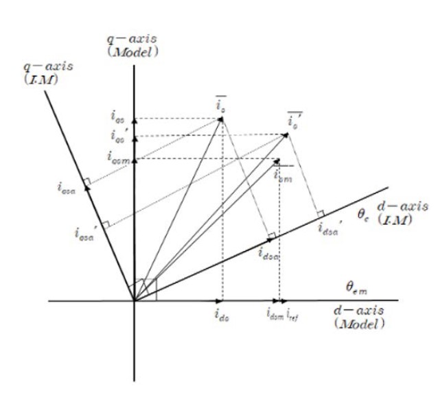
For example, suppose that the d and q axis of the model and motor, along with each stator current, are the same at a certain point in time, as shown in Figure 3. If the value of current is different between the model and inductor, the flux axis can change, as shown in the figure.
As Figure 3 indicates, in the case of iqs > iqsm (i.e., ωτef > ωτ), if Vqs(=Vqsm) is increased, then iqsm and Vqs increase as does the generated torque; thus, because the motor speed increases and then decreases, iqsm → Vqs is derived.
In other words, if Vqs increases, iqsm is increased by Equation (5). Consequently, the model angle speed ωem and the angular speed of the motor ωe(=ωr+ωsl) increase. However, because ωr cannot be increased instantaneously, ωsl increases rapidly. Since the slip frequency decreases according to the amount of increase in the motor speed, iqsa decreases again. Thus, ids-iqsm → 0 is obtained.
Similarly, when iτef>idsm>ids, as shown in the figure, the d axis voltage is increased for greater control, and thus ids, idsm → iτef is established. In addition, iqs for generating torque in the actual induction motor; iτef for vector control with a constant magnetic flux; and the model speed, which is the speed setting, are the reference values of the respective control variables.
If the voltages Vds and Vqs of d and d axes on the synchronous rotation coordinate system of the numerical model are adjusted to achieveids=idm=iτef and iαs=iαsm=iαs′, they converge to the motor and model currents and ′. When the load is constant regardless of the speed, idsa·iqsa=i′dsa·i′qsa.
Furthermore, when the actual flux axis precedes the flux axis of the model, as shown in Figure 3, the slip speed is proportional to the actual torque current and inversely proportional to the flux current. Therefore, as the current control progresses, the actual slip speed decreases by the relationship, and the two flux axes soon become matched. In the opposite case of Figure 3, the flux axis stabilizes at the same flux angle according to the relationship
If ids=idsm=iref, iqs=iqsm=iqs′, and the flux axes of the model and the Jimmy motor are the same, then λqr=0, ρλqr=0, and iqr=. Therefore, Equations (10) and (11) are obtained as follows:
| (12) |
| (13) |
If the flux axis of the model and that of the motor match based on Equations (10) and (12), and ids → iref, then idr = 0. If this is applied to Equation (13), the motor speed ωr approaches the model speedωref.
Therefore, when the difference in the stator voltage between the model and motor for the d and q axes of the numerical model is controlled at zero, the flux angles of both become consistent even if they are different, and the motor speed follows the model speed, which is the command value.
2.2 Control algorithm and characteristics
Based on the theoretical background, sensorless speed control can be conducted through conversion and control as follows. First, the phase current of the motor is detected using the current sensor and converted into a value on the synchronous rotation axis of the numerical model using Equation (14).
| (14) |
under the condition of
Furthermore, after calculating the model current using Equation (2), when applying the supply voltage of the motor, the value of the synchronous rotation axis is obtained through Equation (15).
| (15) |
Subsequently, to achieve control using iqs−iqsm→0ids, idsm → iref(constant), the PI current controller of the synchronous rotation coordinate system is used to calculate the stator voltage input value, as shown through Equation (16).
| (16) |
where Kmp, Kmt, Kms, Ktp, and Ktt are constants.
The conversion of Equation (15) into a value on the fixed coordinate axis through Equation (16) can be expressed as follows:
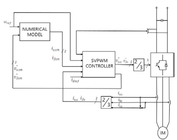
The stator voltage command value calculated using Equation (17) is supplied to each phase through the voltage modulator. Figure 4 shows a block diagram of the proposed sensorless speed control system of an induction motor using a current error compensation.
| (17) |
A smooth control operation can be expected for a majority of existing sensorless control methods for induction motors because a speed estimation is easy to achieve, and the precision is high within the high-speed range. However, because the sizes of all variables such as the input voltage, counter-electromotive force, and frequency are small, an estimation of the accurate speed information is difficult to provide at low speeds. Moreover, when a slight error occurs in the voltage and current sensors accompanied by a change in the motor constant, a stable operation is impossible owing to errors in the speed estimation.
By contrast, the sensorless control method using the current error compensation proposed in this study does not directly estimate or control the speed, unlike existing methods. This is an indirect control method that makes the speed of the motor approach close to the speed of the numerical model by controlling the current, which does not change significantly at a high or low speed.
In other words, the direct control target is not the speed but the three-phase alternating current flowing in the motor. Furthermore, although its magnitude changes depending on the load, the magnitude of the phase current applied to each phase by the flux current is not small even under a zero-load owing to the characteristics of the induction motor; thus, a control operation is relatively easy within the whole range of the speed operation. Accordingly, it has a characteristic in that stable speed control is possible even at an extremely low-speed range of less than 1% of the rated speed.
3.Simulation
To examine the validity of the sensorless speed control algorithm for an induction motor based on the power conversion method proposed in this study, we conducted computer simulations within the ultra-low-speed and low-speed ranges of the inverters with and without the installation of the speed detector, respectively, prior to the experiments.
Table 2 shows the parameters of the induction motor and the system constants used for the computer simulations and experiments.
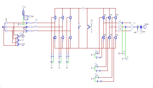
Figure 5 shows a schematic of the PSIM program of the SVPWM-applied sensorless inverter with an AFE rectifier and current error compensation.
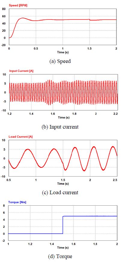
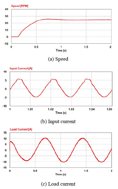
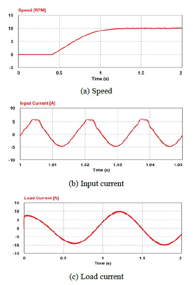
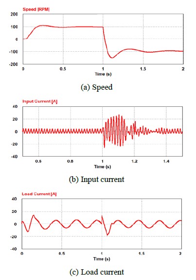
In the simulation, figures were taken at each different time point to check the current in the steady-state or when the load changes. So, the input current and load current of each figure have a different x-axis.
Figure 6 illustrates the response characteristics when a load torque of 5 [N-m] is applied at time T = 1.5 [s] during normal operation at 50 [rpm] with no load. Figure 6 (a) shows a graph of the speed changes of the motor, which indicates that the speed is controlled properly even after the load is applied. Figure 6 (b) shows the phase current waveforms at the input terminal and indicates that the size of the current increases slightly after the load is applied and that the control is achieved properly with a total harmonic distortion (THD) of 3.8 [%]. Figure 6 (c) shows the load current of an induction motor and indicates that the size of the current increases after the load is applied and that the con-trol is stably achieved. Finally, Figure 6 (d) indicates that the torque changes before and after the application of the load torque. The characteristics of the speed control and input/output current and load operation within the low-speed range are similar to those of a speed detector-installed induction motor.
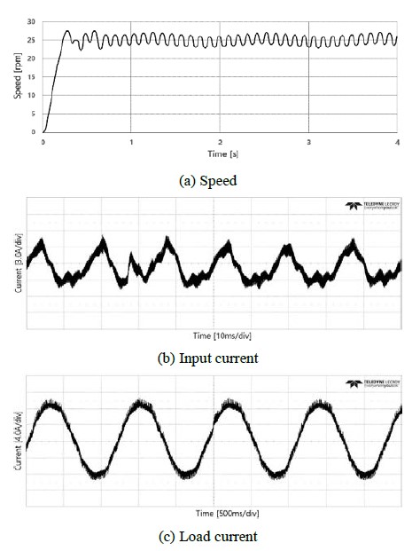
Figure 7 shows a case in which the speed command is applied in steps from 0 to 25 [rpm] in a situation wherein a load of 10 [N-m] is applied. Figure 7 (a) shows the changes in motor speed, and Figure 7 (b) shows the phase current waveforms at the input terminal. Since the THD includes 3.14 [%], an electric current of excellent quality is supplied. Figure 7(c) shows the load current of the motor, and the maximum current under normal conditions is approximately 10.0 [A]. The simulation results show that the characteristics of the speed control and input/output current are extremely satisfactory even within a low-speed range.
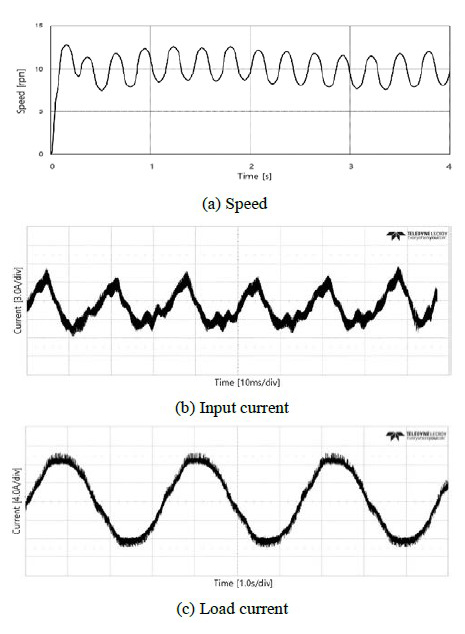
Figure 8 shows the characteristics of the motor when the speed command is applied in steps from 0 to 10 [rpm] at a load of 10 [N-m]. Figure 8 (a) shows the changes in motor speed, and Figure 8 (b) shows the phase current waveforms at the input terminal. Since THD includes 3.29 [%], an electric current of excellent quality is supplied. Figure 8 (c) shows the load current of the motor, and the maximum current under normal conditions is approximately 10.0 [A]. Therefore, it can be inferred that the motor speed control and input/output current characteristics are satisfactory even within an extremely low-speed range.
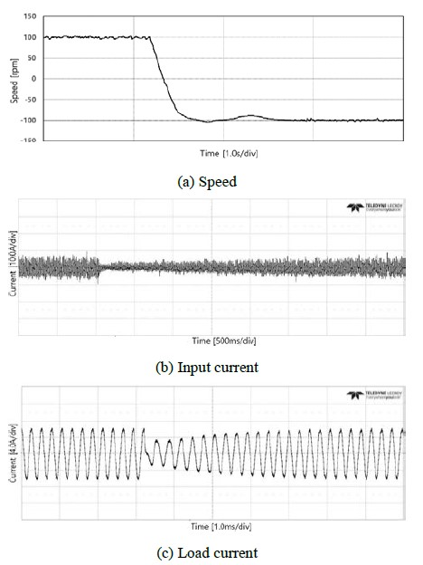
Figure 9 shows the speed response characteristics when the reverse speed command is applied using -100 [rpm] at T = 1 [s] during normal operation at a speed of 100 [rpm] under a state in which the load proportional to the square of the speed is induced. Figure 9 (a) shows a speed graph indicating that the motor speed is controlled stably according to the speed command even when an instantaneous reverse operation is conducted within a low-speed range. Figure 9 (b) phase current at the input terminal shows that stable control is conducted after passing through the transient section even after T = 1 [s], which is the time when the reverse speed command was applied. Finally, Figure 9 (c) shows the load current of the induction motor, and it regains a stable control quickly after the reverse speed com-mand.
4.Experiment
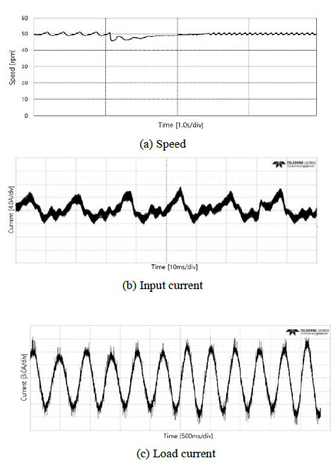
The experimental sequence was the same as the simulation sequence, and the speed and current were stably controlled. The control values of the speed and current of the induction motor are similar to those found in the simulation.
Even in the experiment, the values were measured at each different point in time to check the current while in the steady-state or load changes, as in the simulation.
5.Conclusion
The results of computer simulations and experiments conducted to confirm the applicability of the algorithm and system proposed in this study can be summarized as follows.
The novel control system combines a sensorless speed control method using an AFE rectifier and a current error compensation with current control and an indirect vector control algorithm based on the modified SVPWM. It was demonstrated that the speed response is excellent according to the change in the operating situation within the low-speed range, and the response to the speed command is relatively good even within an extremely low-speed range. Furthermore, it was revealed that the load characteristics are excellent when the load is applied within the low-speed range. Finally, it was confirmed that the response characteristics are excellent when the reverse speed command is applied during normal operation within a low-speed range.
Author Contributions
Conceptualization, J. -J. Hur and J. -S. Kim; Methodology, J. J. Hur; Software, J. -J. Hur; Validation, K. -K. Yoon; Formal analysis, S. -G. Oh; Investigation, Y. -J. Kim, J. -H. Noh, and S. -W. Kim; Writing—Original Draft Preparation, J. -J. Hur; Writing—Review and Editing, J. -S. Kim; Supervision, J. -S. Kim.
References
-
H. Tajima and Y. Hori, “Speed sensorless field-orientation control of the induction machine,” IEEE Transactions on Industry Applications, vol. 29, no. 1, pp. 175-180, 1993.
[https://doi.org/10.1109/28.195904]

-
M. -H. Shin, D. -S. Hyun, S. -B. Cho, and S. -Y. Choe, “An improved atator flux estimation for speed sensorless stator flux orientation control of induction motors,” IEEE Transactions on Power Electronics, vol. 15, no. 2, pp. 312-318, 2000.
[https://doi.org/10.1109/63.838104]

-
M. T. Wishart and R. G. Harley, “Identification and control of induction machines using artificial neural networks,” IEEE Transactions on Industry Applications, vol. 31, no. 3, pp. 612-619, 1995.
[https://doi.org/10.1109/28.382123]

-
M. Wlas, Z. krzeminski, J. Guzinski, H. Abu-Rub, and H. A. Toliyat, “Artificial-neural-network-based sensorless nonlinear control of induction motors,” IEEE Transactions on Energy Conversion, vol. 20, no. 3, pp. 520-528, 2005.
[https://doi.org/10.1109/TEC.2005.847984]

-
J. -H. Kim, S. -S. Lee, R. -Y. Kim, and D. -S. Hyun, “A sensorless control using extended Kalman filter for an IPM synchronous motor based on an extended rotor flux,” IECON 2012 - 38th Annual Conference on IEEE Industrial Electronics Society, pp. 1631-1636.
[https://doi.org/10.1109/IECON.2012.6388731]

- N. M. Tomy and J. Francis, “Modelling and simulation of a hybrid stepper motor in microstepping mode,” International Journal of Advanced Technology in Engineering and Science, vol. 3, no. 9, pp. 31-35, 2015.
-
K. D. Hurst and T, G. Habetler, “Sensorless speed measurement using current harmonic spectral estimation in induction machine drives,” IEEE Transactions on Power Electronics, vol. 11, no. 1, pp. 66-73, 1996.
[https://doi.org/10.1109/63.484418]

-
P. Guglielmi, A. Yousefi-Talouki, G. Iabichino, G. Pellegrino, “Sensorless direct torque control for PM-assisted synchronous motors with injection high-frequency signal into stator flux reference frame,” 2017 IEEE International Symposium on Sensorless Control for Electrical Drives (SLED), pp. 139-144, 2017.
[https://doi.org/10.1109/SLED.2017.8078444]

-
Y. Yu, X. Huang, B. Wang, H. Bu, C. Chen, and D. Xu, “Speed-sensorless vector control with single phase current sensor for induction motor drives using current compensation method,” 2018 21st International Conference on Electrical Machines and Systems (ICEMS), pp. 1590-1594, 2018.
[https://doi.org/10.23919/ICEMS.2018.8549135]

- T. Kikuchi, Y. Noto, H. Mine, and Y. Matsumoto, “Current compensation method for sensorless controlled induction motors operated in low switching frequency,” 2012 15th International Conference on Electrical Machines and Systems (ICEMS), pp. 1-4, 2012.


