A parameter study to improve dimensional accuracy of FDM-type 3D printer based on various filaments
Copyright Ⓒ The Korean Society of Marine Engineering
This is an Open Access article distributed under the terms of the Creative Commons Attribution Non-Commercial License (http://creativecommons.org/licenses/by-nc/3.0), which permits unrestricted non-commercial use, distribution, and reproduction in any medium, provided the original work is properly cited.
Abstract
The purpose of this study is to improve the dimensional accuracy according to the material and size of a given printing object in 3D printing processes using fused deposition modeling (FDM). When printing an object with the selected material, appropriate printing parameters are suggested according to the object size. We experimentally analyze how changes in the material and size of the printing object, and printing parameters such as the extrusion temperature and infill, affect the dimensional error. The experiment was conducted by measuring the dimensional errors in printing specimens of the same shape but various sizes using an FDM-type 3D printer under various printing conditions. Given the material and size of the printing object, it was found experimentally that the dimensional error has the characteristic of a straight line or a parabolic shape according to changes in the extrusion temperature and infill, which are printing parameters. Given the size of the object to be printed, the printing material is appropriately selected by considering the material properties of the required part and the dimensional accuracy of the material obtained through the experiments. It was concluded that printing with appropriate printing parameter values obtained through experiments according to the selected material and size of the printing object can improve the dimensional accuracy of the FDM-type 3D printing process.
Keywords:
Fused deposition modeling, Dimensional accuracy, Extrusion temperature, Infill1. Introduction
Three-dimensional printing technology is a manufacturing technology for creating a 3D object by adding a continuous layer of materials using digital design data [1]. This manufacturing technology is officially called additive manufacturing or rapid prototyping technology. Such printing technology is generally classified into a material extrusion process, a vat photopolymerization process, and a powder bed fusion process [2]. A material extrusion process, such as fused deposition modeling (FDM), is a process of melting and extrusion. A vat photopolymerization process, such as stereolithography, digital light processing, or digital light synthesis, uses a resin that cures when exposed to ultraviolet rays. Powder-bed fusion processes, such as selective laser sintering, electron beam melting, and selective heat sintering, are processes of sintering, melting, and fusing powder particles while tracking the cross-section of an object generated using a laser or electron beam.
Among these processes, the most commonly used is the FDM process [3]. The FDM process has the advantages of a low machine cost, various material processabilities, high component durability, and an adequate processing time [4]-[6]. However, this process generally has the weaknesses of undesirable dimensional accuracy and surface quality [7]. Therefore, the FDM process has some limitations in making parts that require precision machining.
The following studies were conducted to solve these problems. Pérez et al. [8] found that the surface roughness worsens as the layer thickness and height increase, using data obtained by arithmetically averaging the surface roughness profile. Volpato et al. [9] derived a result in which the surface profile of the supporter directly affected the dimensional accuracy of the z-axis and improved the surface quality of the supporter by reducing the gap between layers and the dimensional accuracy of the z-axis. Emre et al. [10] created a linear regression model based on experimental data to determine the correlation between the deviation of the strip width and the parameter of interest. They found that a fast nozzle feed rate and high extrusion temperature can decrease the dimensional accuracy. Belleini et al. [11] improved the dimensional accuracy of printing objects by reducing the nozzle diameter. Moreover, Nancharaiah et al. [12] improved the surface quality and dimensional accuracy by applying a small layer thickness through an analysis of variance (ANOVA) analysis.
In most previous studies, polylactic acid (PLA) and acrylonitrile butadiene styrene (ABS) were used as printing materials. There has yet to be a comparison of dimensional errors of printed objects when printing under various printing conditions for various printing materials. Therefore, in this study, we experimentally studied the effect of each parameter related to printing on the dimensional accuracy by considering the extrusion temperature and infill as printing parameters for various printing materials and object sizes that were not considered in previous studies.
In addition to PLA and ABS, six materials were selected for printing materials with various properties in consideration of their elasticity, soluble properties, and metallic properties. Furthermore, to find appropriate printing parameter values for each material, the highest, medium, and lowest temperatures within the appropriate temperature range for each material provided by the filament manufacturer were selected as the printing parameter values for the extrusion temperature. Although it has been reported that an infill mainly affects the strength of the printed object [13], it was selected as a parameter to check whether it also affects the dimensional accuracy. The infill ratio was assumed to be at a minimum of 10% and a maximum of 50%. Experiments were conducted when the infill ratios were 10%, 30%, and 50%.
For each material, to determine the dimensional error effect according to the size of the printing object, the dimensional error was measured at the three sizes in the horizontal axes (x-and y-axes) and the size in the vertical axis (z-axis). Because the dimensional error is more critical with a small object size, the specimen was modeled to have various dimensions within a relatively small range (1–100 mm).
In this way, the dimensional errors are measured according to the various materials and sizes of the printing object and variations in the extrusion temperature and infill, which are printing parameters. Based on these experimental results, we propose appropriate printing parameter values that can improve the dimensional accuracy according to the material and size of the printing object during FDM-type 3D printing processes. Therefore, by applying the results of this study, it is expected that the dimensional accuracy of printed objects can be improved relatively simply in industrial fields that produce FDM-type 3D printed products.
2.Experimental Environment and Procedure
2.1 Specimen modeling
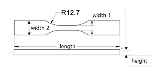
The specimens applied in this experiment were modeled using SolidWorks by slightly deforming an ASTM D638 type V tensile test specimen. Because the tensile test specimen is a model with an essential dimensional accuracy, it was judged to be an appropriate specimen based on the purpose of the experiment. In general, the smaller the object is, the more critical the dimensional error. Therefore, among the specimens used in the tensile test, an ASTM D638 type V, which is relatively small in size, was selected. However, although the tensile test specimen was cylindrical, this study compared the dimensional errors between the x-and y-axes and the z-axis, and tensile test specimen with a cross-section having a z-axis height of 3 mm, as shown in Figure 1, was modeled. Table 1 lists the dimensions of the ASTM D638 tensile test specimen.
2.2 Experimental equipment
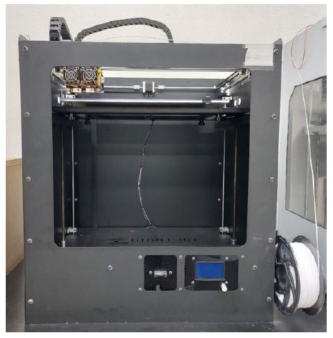
Figure 2 shows the FDM-type 3D printer, a GIANTBOT G5 Plus, used to print the modeled specimen, as shown in Figure 1. The printer pulls the filament-shaped material through a nozzle, heats it, extrudes it, and stacks it layer by layer on a build platform. A nozzle with a diameter of 0.4 mm moves in the x-and y-axes directions, and the build platform moves in the z-axis direction. The extrusion temperature of this 3D printer can increase to 300 °C, but for safety, is designed to stop printing through a maximum temperature error when it increases to approximately 250 °C. Therefore, if the range of the proper printing temperature for a specific material exceeds 250 °C, printing cannot be achieved within that range of extrusion temperature. The diameter of the filaments of all materials used in this experiment was 1.75 mm. Printing was achieved by applying a nozzle feed rate to all materials of 2520 mm/min.
2.3 Selection of materials and printing parameters of printing objects
The materials of the printing object used in this experiment were PLA and ABS, as mainly applied in previous studies, along with high-impact polystyrene (HIPS), polyvinyl alcohol (PVA), eSteel, and thermoplastic polyurethane (TPU). The materials were selected to consider the solubility, metallicity, elasticity, and toughness and analyze the effect of the properties of each material on the dimensional accuracy. HIPS and PVA are soluble materials that dissolve in limonene and water, respectively. In addition, eSteel is a metallic material, including stainless steel, and TPU is a material with a high elasticity.
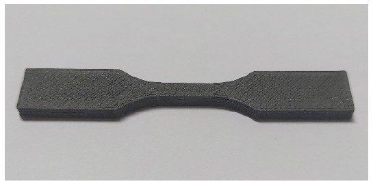
This experiment analyzed the effect of the extrusion temperature on the dimensional error. The highest, medium, and lowest temperatures within the appropriate temperature range for each material provided by the filament manufacturer were selected as the printing parameter values. In addition, the infill, which significantly affects the strength and weight reduction of printing objects, was added as a printing parameter. In this study, it was assumed that the infill ratio was between 10% and 50%. Experiments were conducted for relatively small, medium, and large cases by selecting three parameter values, i.e., 10%, 30%, and 50% of the infill for all materials to determine the effect of the infill on the dimensional accuracy. Figure 3 shows the specimen printed using an FDM-type 3D printer GIANTBOT G5 Plus under one of the above conditions.
During this experiment, four measuring sizes were selected for the specimen, as shown in Figure 1. The dimensional errors were measured at the four measurement locations under the nine-printing conditions according to three extrusion temperatures and three infill ratios for each of the six materials. The dimensional error was obtained from the average values measured at three arbitrary points for each measurement size. The variation of the dimensional error representing the roughness of the printing object surface is approximately 0.02 mm. The effect was insignificant when selecting the appropriate extrusion temperature and infill parameters to improve the dimensional accuracy according to the material and size of the printing object. By comparing and analyzing these dimensional errors, we propose an appropriate extrusion temperature and infill ratio to improve the dimensional accuracy of the printing object according to its material and size.
3.Experimental Results and Discussion
3.1 Experimental results
For each of the materials considered for this experiment, the size of the test specimen shown in Figure 1 and Table 1 was appropriately divided into classes W1, W2, and L shown along the x-and y-axes, and H shown along the z-axis. Dimensional errors owing to changes in the extrusion temperature and infill ratio were measured. To compare and analyze these data, the experimental results are shown in Figures 4-15 and Tables 2-9.
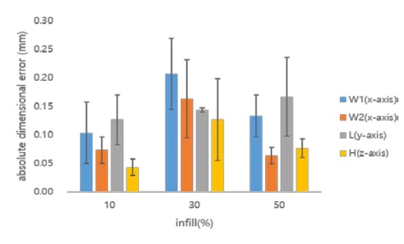
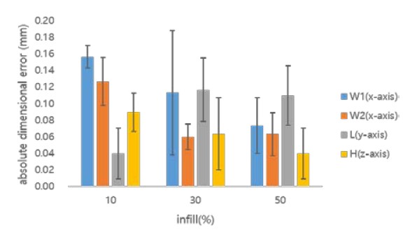
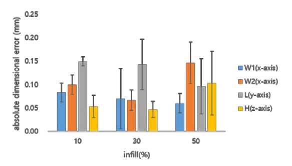
Figures 4 and 5 show the dimensional errors according to the extrusion temperature and infill, respectively, for the printing object size when using PLA. The bars shown in Figures 4 and 5 represent the absolute dimensional error, averaging the dimensional errors according to the change in infill at a given extrusion temperature and according to the change in the extrusion temperature of a given infill. The lines shown above the bars in Figures 4 and 5 show the width of the dimensional error variation owing to the allowed infill and extrusion temperature changes, respectively. Table 2 shows the dimensional errors considered for both the extrusion temperature and the infill parameters when using the PLA. The dimensional errors eW1, eW2, eL, and eH shown in Table 2 represent the dimensional errors measured for W1, W2, and L along the x-and y-axes and H along the z-axis.
Dimensional error according to extrusion temperature for the size of the printing object when using material PLA

Dimensional errors (eW1, eW2, eL, eH; unit: mm) accord-ing to the extrusion temperature and infill when using material PLA
As shown in Figures 4 and 5, when PLA is used, the error eH for H along the z-axis and error eW1 for W1 along the x-and y-axes are compared. It can be seen that eH is relatively small compared with eW1 within the considered range of the changes in the extrusion temperature and infill. Therefore, the dimensional accuracy of an object can be determined based on the dimensional errors in the x-and y-axes.
The dimensional error characteristics of the PLA, shown in Figures 4 and 5 and Table 2, were comprehensively analyzed. It can be seen that as the extrusion temperature increases, the dimensional error increases at almost a constant rate and decreases for W1, W2, and L, respectively. In addition, it can be seen that as the amount of infill increases, for W1 or W2, the dimensional error forms an upwardly convex parabolic shape. The size of L also increases.
For W1, the dimensional error is almost zero at an extrusion temperature of 195 °C and an infill of 10%. In W2, a dimensional error of 0.03 mm occurs at an extrusion temperature of 220 °C and an infill of 10%. For L, a dimensional error of 0.04 mm occurs at an extrusion temperature of 220 °C and an infill of 50%. The dimensional accuracy was extremely high under these conditions. However, for W1, a dimensional error of 0.29 mm occurs at an extrusion temperature of 220 °C and an infill of 30%, resulting in low dimensional accuracy.
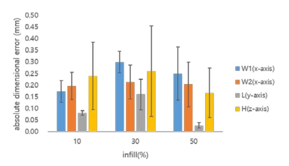
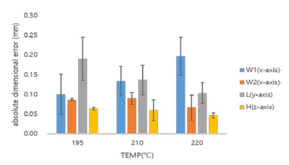
Figures 6 and 7 show dimensional errors according to changes in the extrusion temperature and infill for W1, W2, and L along the x-and y-axes, and for H along the z-axis, using the ABS material, respectively. Table 3 shows the dimensional errors considered for both the extrusion temperature and infill parameters when using the ABS material.
Dimensional error according to extrusion temperature for each size of the printing object when using ABS material

Dimensional errors (eW1, eW2, eL, eH; unit: mm) accord-ing to extrusion temperature and infill when using ABS material
As shown in Figures 6 and 7, when the ABS material is used, eH and eW1 are compared. Error eH was found to be smaller than or equal to eW1 within the range where changes in the extrusion temperature and infill were considered. Therefore, the dimensional accuracy of an object can be determined by the dimensional errors in the x-and y-axes. Figures 6 and 7 and Table 3, which show the comprehensively analyzed dimensional error characteristics of ABS. As the extrusion temperature increases, the dimensional error becomes a downwardly convex parabolic shape for W1, is almost constant for W2, and becomes an upwardly convex parabolic shape for L. It can be seen that, as the amount of infill increases, the dimensional error decreases for W1, becomes a downwardly convex parabolic shape for W2, and becomes an upwardly convex parabolic shape for L.
For W1, a dimensional error of 0.01 mm occurs at an extrusion temperature of 235 °C and an infill of 30%. A dimensional error of 0.02 mm occurs at an extrusion temperature of 235 °C and an infill of 50% for W2. There are almost no dimensional errors at an extrusion temperature of 240 °C and an infill of 10% for L. Therefore, the dimensional accuracy is extremely high in these cases. However, for W1, a dimensional error of 0.26 mm occurs at an extrusion temperature of 230 °C and an infill of 30%, resulting in a low dimensional accuracy.
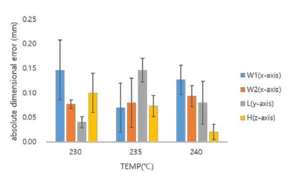
Figures 8 and 9 show the dimensional error owing to changes in the extrusion temperature and infill for W1, W2, and L along the x-and y-axes, and for H along the z-axis, when using the HIPS material, respectively. Table 4 shows the dimensional errors when considering both the extrusion temperature and infill parameters when applying the HIPS material.
Dimensional error according to extrusion temperature for the size of the printed object when using HIPS material

Dimensional errors (eW1, eW2, eL, eH; unit: mm) accord-ing to extrusion temperature and infill when using HIPS material
Errors eH and error eW1 were compared when the HIPS material is used, the results of which are shown in Figures 8 and 9. It was found that eH is small compared with eW1 within the range of the appropriate extrusion temperature. Therefore, the dimensional accuracy of an object can be determined based on the dimensional errors along the x-and y-axes.
The dimensional error characteristics of the HIPS material were comprehensively analyzed, as indicated in Figures 8 and 9 and Table 4. The dimensional error forms a downwardly convex parabolic shape for W1 and W2 as the extrusion temperature increases, and increases with L. In addition, as the amount of infill increases, it can be seen that the dimensional error has an upwardly convex parabolic shape regardless of the error and has an upwardly convex parabolic shape regardless of the object size.
For W1, a dimensional error of 0.08 mm occurs at an extrusion temperature of 230 °C and an infill of 10%. For W1 and L, dimensional errors of 0.07 and 0.01 mm occur, respectively, at an extrusion temperature of 240 ℃ and an of infill 50%. Therefore, the dimensional accuracy is extremely high in these cases. However, for W1, a dimensional error of 0.48 mm occurs at an extrusion temperature of 220 °C and an infill of 50%, resulting in low dimensional accuracy.
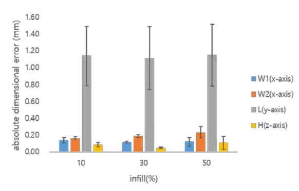
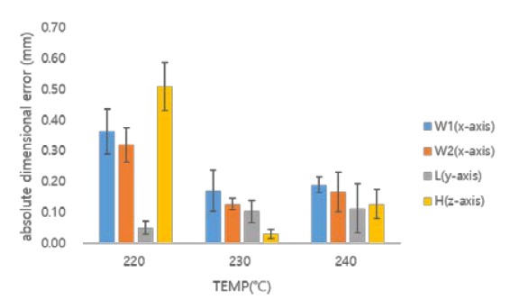
Figures 10 and 11 show the dimensional error owing to changes in the extrusion temperature and infill for W1, W2, and L along the x-and y-axes, and for H along the z-axis, when using PVA, respectively. Table 5 shows the dimensional errors when considering both the extrusion temperature and infill parameters when applying the PVA.
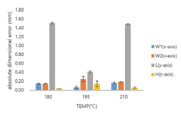
Dimensional error according to extrusion temperature for the size of the printed object when using PVA material

Dimensional errors (eW1, eW2, eL, eH; unit: mm) accord-ing to extrusion temperature and infill when using PVA material
As shown in Figures 10 and 11, eH and eW1 were compared when PVA is used. Error eH was found to be smaller than eW1 within the range in which changes in the extrusion temperature and infill were considered. In particular, for L, the medium extrusion temperature becomes the appropriate extrusion temperature. Therefore, for W1 or W2, the dimensional accuracy may be evaluated based on the dimensional errors along the x-and y-axes.
Figures 10 and 11 and Table 5, which show the dimensional error characteristics of PVA, are comprehensively analyzed. As the extrusion temperature increases, the dimensional error forms a downwardly convex parabolic shape for W1 or L. It forms an upward convex parabolic shape for W2. As the amount of infill increases, the dimensional error becomes almost constant regardless of the size of the object. In particular, it can be seen that a substantial dimensional error occurs for L.
For W1, the dimensional accuracy is good because of the dimensional error of 0.01 mm at the extrusion temperature of 195 °C and an infill of 50%. However, for W2 and L, dimensional errors of 0.36 and 1.56 mm occur at extrusion temperatures of 195℃ and 180℃, respectively, and an infill of 50%, resulting in an extremely low dimensional accuracy.
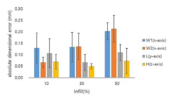
Figures 12 and 13 show the dimensional error owing to the change in extrusion temperature and infill for W1, W2, and L along the x-and y-axes, and for H along the z-axis, when using eSteel material, respectively. Table 6 shows the dimensional errors considered for both the extrusion temperature and infill parameters when using eSteel material.
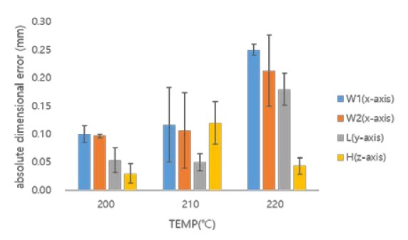
Dimensional error according to extrusion temperature for the size of the printed object when using eSteel material

Dimensional errors (eW1, eW2, eL, eH; unit: mm) according to extrusion temperature and infill when using eSteel material
Figures 12 and 13 show that when eSteel is used, eH and eW1 are compared. Error eH was found to be smaller than or equal to eW1 within the range in which changes in the extrusion temperature and infill are considered. Therefore, the dimensional accuracy of an object can be determined based on the dimensional errors along the x-and y-axes.
The dimensional error characteristics of the eSteel material were comprehensively analyzed, as shown in Figures 12 and 13 and Table 6. It can be seen that, as the extrusion temperature increases, the dimensional error increases for W1 and W2. For L, it forms a downwardly convex parabolic shape. In addition, as the infill increases, it can be seen that the dimensional error forms a downwardly convex parabolic shape for W1 and L and increases for W2.
For W1 and W2, dimensional errors of 0.05 and 0.02 mm occur at an extrusion temperature of 210 ℃ and an infill of 10%, respectively. For L, a dimensional error of 0.01 mm occurs at an extrusion temperature of 200 °C and an infill of 30%. Therefore, the dimensional accuracy was excellent in these cases. However, for W2, a dimensional error of 0.3 mm occurs at an extrusion temperature of 220 °C and an infill of 50%, resulting in relatively low dimensional accuracy.
Figures 14 and 15 show the dimensional error according to the change in extrusion temperature and infill for W1, W2, and L along the x-and y-axes, and for H along the z-axis, when the TPU material is used, respectively. Table 7 shows the dimensional errors considering both the extrusion temperature and infill parameters when using the TPU.
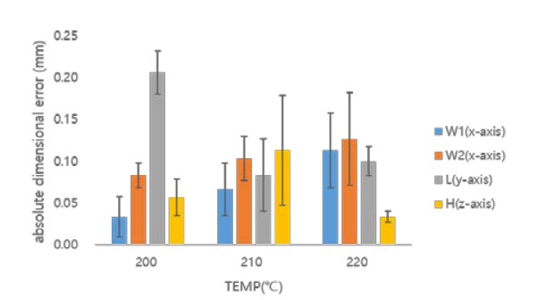
Dimensional error according to extrusion temperature for the size of the printed object when using TPU material

Dimensional errors (eW1, eW2, eL, eH, unit: mm) accord-ing to extrusion temperature and infill when using TPU material
As shown in Figures 14 and 15, when the TPU material is used, eH and eW1 are compared, except for at the high extrusion temperature. At medium extrusion temperatures, it can be seen that eH is approximately twice that of eW1. Within the medium extrusion temperature region where the dimensional accuracy is relatively high, it was found that it is unreasonable to consider only the dimensional error along the x-and y-axes when determining the dimensional accuracy according to the object size, as with the other materials.
The dimensional error characteristics of the TPU material are analyzed comprehensively in Figures 14, 15, and 7. It can be seen that as the extrusion temperature increases, the dimensional error increases for W1 and W2. For L, it forms a downwardly convex parabolic shape. It can be seen that, as the infill increases, the dimensional error decreases for W1 and L, and forms a downward convex parabolic shape for W2.
For W1, the dimensional error is almost zero at an extrusion temperature of 200 °C and an infill of 30%. For W2, a dimensional error of 0.05 mm occurs at an extrusion temperature of 210 °C and an infill of 30%. For L, a dimensional error of 0.01 mm occurs at an extrusion temperature of 210 °C and an infill of 50%. Therefore, the dimensional accuracy was outstanding under these conditions. However, for L, a dimensional error of 0.25 mm occurs at an extrusion temperature of 200 °C and an infill of 30%, resulting in a relatively low dimensional accuracy. The TCU material has excellent overall dimensional accuracy regardless of the size of the object.
3.2 Discussion of experimental results
Table 8 lists the appropriate extrusion temperature and infill according to the material and size of the printing object. The first and second data in Table 8 are the appropriate extrusion temperature and infill according to the object material and size, and the third is the dimensional error for the appropriate printing conditions.

Appropriate extrusion temperature (°C), infill (%), and dimensional error (mm) according to the material and size of the printing object, respectively
From the experimental results, when selecting the appropriate printing parameters, the dimensional error eH along the z-axis is generally approximately 50% less than or equal to the dimensional error eW1 along the x-and y-axes. Therefore, the size of the printing object is considered only in the x-and y-axes.
The third type of data, the dimensional error, is used when manufacturing general objects consisting of two or more different sizes. If the dimensional error in a specific part of a printing object is critical, it should be printed with appropriate printing parameters selected based on the size of the part. Otherwise, we should print the object using the appropriate printing parameters selected under the printing condition in which the dimensional error in the third data is relatively large. Therefore, for a printing object of three different sizes, appropriate printing parameters are selected for the size of the printing object with the largest dimensional error. Thus, printing with these parameters can increase the dimensional accuracy of the printing object.
We suppose that the printing material and infill ratios of 10%, 30%, and 50% were selected when considering the strength and weight reduction of the object. The appropriate extrusion temperature and dimensional error under these conditions are listed in Table 9. Table 9 shows two data: an appropriate extrusion temperature and a dimensional error. An appropriate extrusion temperature was selected to minimize the maximum dimensional errors measured for W1, W2, L, and H for three extrusion temperatures. The dimensional error is the value measured at an appropriate extrusion temperature. When the dimensional error forms a downward convex parabolic shape according to the extrusion temperature, we find a quadratic equation satisfying the three data points according to the extrusion temperature. We can then find an appropriate extrusion temperature and minimum dimensional error to improve the dimensional accuracy.

Appropriate extrusion temperature (℃) and dimen-sional error (mm) according to the material and infill ratio of the printing object, respectively
As shown in Table 9, considering only the dimensional accuracy, eSteel, TPU, and PLA were selected as printing materials under infill ratios of 10%, 30%, and 50%, respectively, for printing an object with various sizes of between 1 and 100 mm.
In this paper, we proposed a method for finding a printing condition that can improve the dimensional accuracy of the printing object, given the material and size. This research procedure can be applied to improve the dimensional accuracy of the shape of the printing object, such as squares, rectangles, circles, and ellipses. In the future, if research such as this will be conducted, the dimensional accuracy can be improved in FDM-type 3D printing processes.
In FDM-type 3D printing processes, the additive direction is also expected to affect the dimensional accuracy of the printed object. However, because the objective of this study is to select appropriate printing parameters according to the material and size of the printing object, lamination was applied automatically in the direction set by Simplify3D software during all experiments. Therefore, a study on the effect of the dimensional accuracy according to the additive direction is expected to be an excellent area of future research.
In addition, studies evaluating the reliability of the selected printing parameters to improve the dimensional accuracy can be conducted in the future. The experimental data obtained under various conditions were statistically processed through an ANOVA analysis.
4.Conclusion
In FDM-type 3D printing processes, when the material and size of the printing object are given, printing parameters such as the extrusion temperature and infill can be appropriately selected to improve the dimensional accuracy of the printing object based on the experimental results. For this purpose, test specimens with different sizes were printed while varying the printing parameters of the extrusion temperature and infill. The dimensional error of the object was then measured and analyzed. Given the material and sizes of the printing object, it can be seen that the dimensional error has the characteristic of a straight line or a parabolic shape according to the changes in the extrusion temperature and infill, which are printing parameters. From the experimental results, the dimensional error in the z-axis is generally smaller than or equal to those in the x-and y-axes when selecting appropriate printing parameters. Therefore, it was found that, for the dimensional accuracy based on the size of the printing object, only the sizes along the x-and y-axes need to be considered. This can also improve the dimensional accuracy of FDM-type 3D printing processes through the selection of an appropriate printing material and appropriate printing parameters for simple-and general-sized printing objects.
Acknowledgments
This research was supported by Basic Science Research Program through the National Research Foundation of Korea (NRF) funded by the Ministry of Education and Ministry of Science (2019R1G1A1009980).
Author Contributions
Conceptualization, J. Ko; Methodology, J. Kim and J Ko; Software, J. Kim; Formal Analysis, J. Kim; Investigation, J. Kim; Resources, J. Ko; Data Curation J. Kim; Writing-Original Draft Preparation, J. Kim; Writing-Review & Editing, J. Ko; Visualization, J. Kim; Supervision, J. Ko; Project Administration, J. Ko; Funding Acquisition, J. Ko.
References
- K. Cummins, The Rise of Additive Manufacturing, https://www.theengineer.co.uk/the-rise-of-additive-manufacturing/, , 2010 Oct. 10th.
- J. S. Kim, S. H. Park, S. Park, M. C. Lee, Creative Engineering Design, Seoul, Korea, Books-Hill, 2016.
-
R. Singh, “Some investigations for small-sized product fabrication with FDM for plastic components,” Rapid Proto-typing Journal, vol. 19, no. 1, pp. 58-63, 2013.
[https://doi.org/10.1108/13552541311292745]

-
X. Yan and P. Gu, “A review of rapid prototyping technologies and systems,” Computer-Aided Design, vol. 28, no 4, pp. 307-318, 1996.
[https://doi.org/10.1016/0010-4485(95)00035-6]

-
C. A. Griffiths, J. Howarth, G. De Almeida-Rowbotham, and A. Rees, “A design of experiments approach to optimise tensile and notched bending properties of fused deposition modelling parts,” Proceedings of the Institution of Mechanical Engineers, Part B: Journal of Engineering Manufacture, vol. 230, no. 8, pp. 1502-1512, 2016.
[https://doi.org/10.1177/0954405416640182]

-
M. Raju, M. K. Gupta, N. Bhanot, and V. S. Sharma, “A hybrid PSO–BFO evolutionary algorithm for optimization of fused deposition modelling process parameters,” Journal of Intelligent Manufacturing, vol. 30, pp. 2743-2758, 2019.
[https://doi.org/10.1007/s10845-018-1420-0]

-
J. Winder and R. Bibb, “Medical rapid prototyping technologies: State of the art and current limitations for application in oral and maxillofacial surgery,” Journal of Oral and Maxillofacial Surgery, vol. 63, no. 7, pp. 1006-1015, 2005.
[https://doi.org/10.1016/j.joms.2005.03.016]

-
M. Pérez, G. Medina-Sanchez, A. Garcia-Collado, M. Gupta, and D. Carou, “Surface quality enhancement of fused deposition modeling (FDM) printed samples based on the selection of critical printing parameters,” Materials, vol. 11, no. 8, pp. 1382-1394, 2018. https://doi.org/10.3390/ma11081382.
[https://doi.org/10.3390/ma11081382]

-
N. Volpato, J. A. Foggiatto, and D. C. Schwarz, “The influence of support base on FDM accuracy in Z,” Rapid Prototyping Journal, vol. 20, no. 3, pp. 182-191, 2014. https://doi.org/10.1108/RPJ-12-2012-0116.
[https://doi.org/10.1108/RPJ-12-2012-0116]

-
O. E. Akbas, O. Hira, S. Z. Hervan, S. Samankan, and A. Altinkaynak, “Dimensional accuracy of FDM-printed polymer parts,” Rapid Prototyping Journal, vol. 26, no. 2, pp. 288-298, 2019.
[https://doi.org/10.1108/RPJ-04-2019-0115]

-
A. Bellini, S. Guceri, and M. Bertoldi, “Liquefier dynamics in fused deposition,” Journal of Manufacturing Science and Engineering, vol. 126, no. 2, pp. 237-246, 2004.
[https://doi.org/10.1115/1.1688377]

- T. Nancharaiah, D. R. Raju, V. Ramach, and R. Raju, “An experimental investigation on surface quality and dimensional accuracy of FDM components,” International Journal on Emerging Technologies, vol. 1, no. 2, pp.106-111, 2010.
-
J. -W. Kim, H. Kim, and J. Ko, “Effect of changing printing parameters on mechanical properties of printed PLA and Nylon 645,” Journal of Advanced Mechanical Design, Systems, and Manufacturing, vol. 14, no. 4, pp. JAMDSM0056, 2020.
[https://doi.org/10.1299/jamdsm.2020jamdsm0056]


