Inductive coupling characteristics of air-core toroid coil and its application in power line communication
Copyright © The Korean Society of Marine Engineering
This is an Open Access article distributed under the terms of the Creative Commons Attribution Non-Commercial License (http://creativecommons.org/licenses/by-nc/3.0), which permits unrestricted non-commercial use, distribution, and reproduction in any medium, provided the original work is properly cited.
Abstract
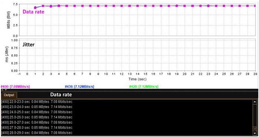
In this study, a circular solenoid, which is the basic structure of a non-contact current sensor, was modified and applied to an air-core inductive coupler for power line communication. The COMSOL AC/DC module, a multiphysics modeling package software, was used for modeling and inductive coupling analysis of the proposed coupler. Based on the analysis results, circular coils with 5, 10, and 20 windings were fabricated using plastic bobbins and RF cables. In terms of the frequency spectrum response of these coils, the 10-turn coil is the most suitable for broadband power line communications with a frequency band of 2–35 MHz. In the 10-turn coil inductive coupler performance test, we used Jperf, a type of network traffic measurement program, to measure the data rate and jitter on a 30 m power line. The average data rate measured repeatedly at 1-s intervals for 30 s was 7 Mbps, and very stable communication was achieved without errors or jitter during testing.
Keywords:
Inductive coupler, Solenoid, Air-core coil, Power line communication, Inductive current sensor1. Introduction
Power lines are a type of network with a very broad infrastructure for all buildings, vehicles, and ships. Because it is possible to construct a communication network at low cost, the scope of application is expanding to remote power meter reading, smart grids, smart homes, and the Internet of Things [1]-[3]. Using a power cable connected to an electronic device, we can turn on the power, control, and retrieve data in a half-duplex manner.
There are two ways to connect a high-frequency signal to a power cable: a contact method using an electric field and a non-contact method using a magnetic field induction [4]. Because the former mainly uses passive elements such as capacitors, it has good signal transmission characteristics but requires physical contact with the power line; thus, installation and maintenance are limited.
The latter uses a magnetic-core-type coupler to be installed without physical contact with the power line. Therefore, it exhibits excellent electrical stability. When ferrite or nanocrystalline material is used as the magnetic core, the flux density is higher than that of the air core, and the coupling efficiency is much better. However, magnetic saturation occurs above a certain current and exhibits a magnetic hysteresis curve. This phenomenon becomes more severe in the high-frequency region. Recently, air gap cores have been used to resolve this problem [5]-[7].
Conversely, solenoids without a magnetic core are used as sensors to measure large currents because magnetic saturation does not occur. Although there is no metal core, the winding forms a constant cross-sectional area, and hence, the principle of electromagnetic induction by Faraday's law is applied to the coil analysis [8].
Rogowski coils that have evolved from air-core solenoids are being used as various types of non-contact AC current-measuring sensors [9]-[11]. However, when the operating frequency is less than 500 kHz, it detects a current of 1 A or less; however, at a high frequency in the range of megahertz or more, it responds to a current of 1 A or more. Thus, it is not suitable for use as an inductive coupler that must respond to the low signal strength of power lines.
In this paper, we propose an air-core coil coupler suitable for non-contact broadband power line communication. The coupler was modeled and characterized by the COMSOL Multiphysics® AC/DC module. The performance of the coupler was evaluated based on the data rate and jitter.
2. Operating principle
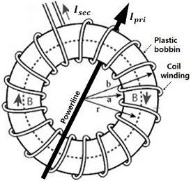
Figure 1 shows a schematic diagram of an air-core coil with a copper wire evenly wound around a plastic bobbin. Unlike Rogowski coils made in such a way that the end point of the start winding returns to the start point along the central axis of the bobbin, the proposed coupler does not have a return winding [12].
Consider the conductive element dr at distance r from the origin and assume that the current-carrying conductor is located in the center of the coil. According to Biot-Savart's law, when a primary current (Ipri) flows through an infinitely small conductor length, the magnetic field (dH) generated by this current is as shown in Equation (1) [13].
| (1) |
Using the relational formula B=μ0H between the magnetic field and flux density in free space, the flux density is given by Equation (2).
| (2) |
where μ0 is the permeability of the free space. The magnetic flux (∅) passing through a certain cross-sectional area inside the coil is given by Equation (3):
| (3) |
where h is the width of the toroid core and dA is the rectangular cross-sectional area of the small-section dr.
The working principle of the air-core coil is similar to that of the AC current transformer. According to Faraday’s law of induction, a time-variant current can generate an alternating magnetic field. Then, the generated magnetic field induces an AC voltage at the coil terminals, which can be obtained using Equation (4).
| (4) |
where N is the number of turns. The inner radius and outer radius are defined as a and b, respectively. If the secondary resistance and induction are negligibly small, the secondary currents (Isec) are specified as .
3. Coupler modeling and simulation
In power line communication, the inductive coupler must connect and extract the signal from the transmission line. Two types of coupling phenomena were analyzed using the COMSOL AC/DC module, a finite element analysis program.
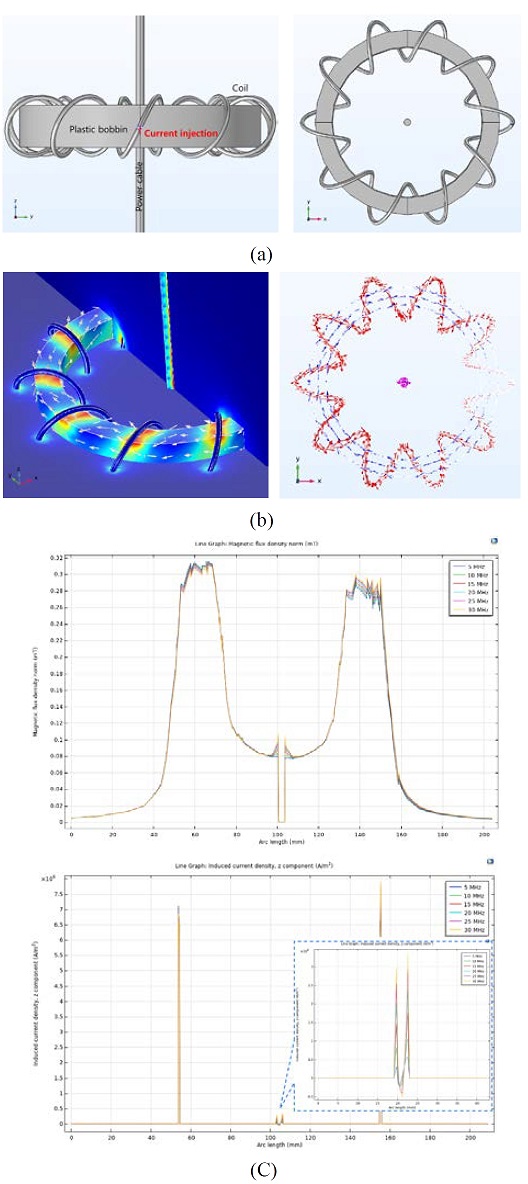
Figure 2 shows a model of a coupler used to analyze electromagnetic induction from a power line to a coil. As shown in Figure 2 (a), the coil was modeled as the winding wound on a bobbin. The outer and inner radii of the bobbin were 44 mm and 36 mm, respectively, and the coil diameter was 20 mm. A current of 1 A flows through the power line located at the center of the coupler. Figure 2 (b) shows the flux density on the surface of the 3D coupler. This shows that the electric current in the power line creates a magnetic field inside the coil and induces a current in the coil. The flux density and current density along the core midline are shown in Figure 2 (c) and Figure 2 (d), respectively. The current density induced in the coil was approximately 105 A/m2, which is a tenth of the power line current density.
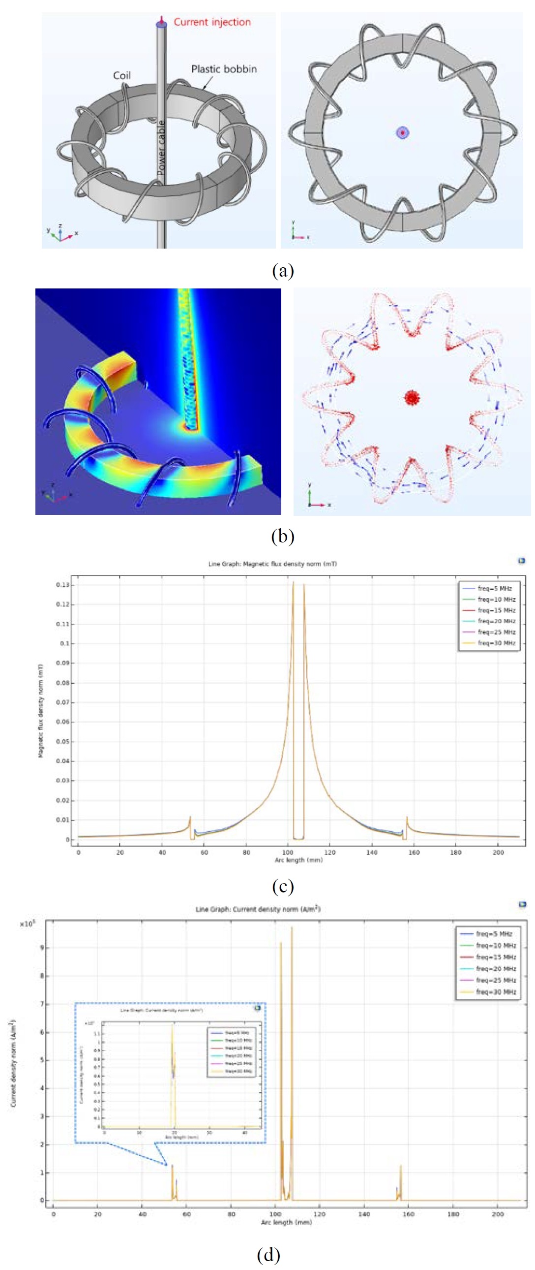
Coupler analysis when 1 A current is injected into the power line: (a) Model of 10-turn coil coupler, (b) 3D flux density, (c) flux density and (d) current density along core median line
Figure 3 shows that the current from the coil is induced into the power line. As shown in Figure 3 (a), one end of the coil was set as an input port and a current of 1 A was injected into it. Figure 3 (b) shows the flux density on the 3D surface of the coupler. When the coil current forms a magnetic field around the power line, a current is induced in the power line. Magnetic flux density and current density along the core midline are shown in Figure 3 (c) and (d) respectively. The induced current density is approximately ~3× 10⁵ A/m2, which is a twentieth of the coil current density.
4. Experimental results and discussion
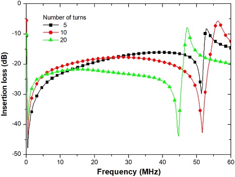
Figure 4 shows hand-made coil couplers used for the experiment. Each bobbin is wound with 5, 10 and 20 turns using an RF cable. The bobbin is a plastic implant to maintain the shape of the toroid coil. The transfer function of the coils is shown in Figure 5. The transmission bandwidth of the coil is well matched to that of broadband power line communication. In the case of a five-turn coupler, the insertion loss in the low-frequency region is larger than that in the high-frequency region. For 10 turns, the spectrum is symmetrical around 30 MHz, and the bandwidth is formed between 5 MHz and 45 MHz. However, when the winding reaches 20 turns, the upper cut-off frequency is lowered to less than 40 MHz, and the insertion loss in the high-frequency region is higher than that in the low-frequency region. Considering the coil's bandwidth and insertion loss, a 10-turn coil was determined to be optimal for our experiment.
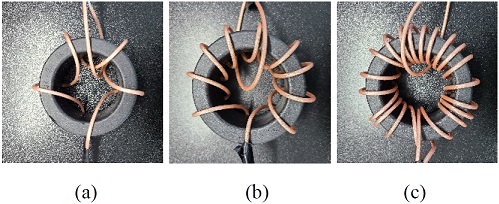
An air-core inductive coupler manufactured by winding an RF cable around a plastic bobbin: (a) 5 turns, (b) 10 turns, and (c) 20 turns
Figure 6 shows the experimental setup for measuring the data rate and jitter. Two identical 10-turn couplers were installed at both ends of the 30 m long power cable. The PLC modem used was MM-D200-A (Mattron Co., Ltd, Korea), which supports transmission speeds of up to 200 Mbps at an operating frequency of 2–34 MHz. Jperf, a program for measuring network traffic, runs on monitoring PCs.
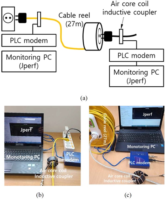
Power line communication performance experiment: (a) experiment schematic, (b) client, and (c) server
The data rates measured three times over 30 s at 1-s intervals are shown in Figure 7. The average data rate obtained by interval repetition measurement was 7 Mbps, and jitter owing to irregular packet delay during communication was not observed. Despite the insertion loss of −20 dB, the proposed coupler operates stably in an inductive power line communication system.
5. Conclusion
In this study, we proposed and demonstrated that an air-core coil can be used as an inductive coupler for power line communication. The coupler was modeled and simulated using the finite element analysis program COMSOL AC/DC module. A 30 m long power cable equipped with 10 coil turns was found to have a power line communication bandwidth of 7 Mbps. In low-speed IoT applications that transmit sensor data intermittently, the communication range can be extended to hundreds of meters. We expect that the proposed system can be used to build a communication network using the power cables in shipyards, ships, or smart factories.
Acknowledgments
This research was supported by through the development of local specialized industries of Ministry of SMEs and Startups(S2850657).
Author Contributions
Conceptualization, K. Sohn and H. Kim; Methodology, K. Sohn and H. Kim; Software, K. Sohn; Validation, K. Sohn and H. Kim; Formal Analysis, K. Sohn; Investigation, K. Sohn and H. Kim; Resources, K. Sohn and H. Kim; Data Curation, K. Sohn; Writing—Original Draft Preparation, K. Sohn; Writing—Review & Editing, K. Sohn and H. Kim; Visualization, K. Sohn; Supervision, K. Sohn; Project Administration, K. Sohn and H. Kim; Funding Acquisition, K. Sohn and H. Kim.
References
-
A. M. Tonello and A. Pittolo, “Considerations on narrowband and broadband power line communication for smart grids,” IEEE International Conference on Smart Grid Communications, pp. 13-18, 2015.
[https://doi.org/10.1109/SmartGridComm.2015.7436269]

-
Y. Xu, Y. Li, X. Xiao, Z. Xu, and H. Hu, “Monitoring and analysis of electronic current transformer’s field operating errors,” Measurement, vol. 112, pp. 117-124, 2017.
[https://doi.org/10.1016/j.measurement.2017.08.015]

-
J. Jeong and K. Sohn, “Study on power line communication for high voltage cables of electric vehicles,” Journal of Advanced Marine Engineering and Technology, vol. 44, no. 1, pp. 63-67, 2020.
[https://doi.org/10.5916/jamet.2020.44.1.63]

-
A. Kosonen and J. Ahola, “Comparison of signal coupling methods for power line communication between a motor and an inverter,” IET Electric Power Applications, vol. 4, no. 6, pp. 431-440, 2010.
[https://doi.org/10.1049/iet-epa.2009.0114]

- H. S. Kim, W. J. Ju, and K. R. Sohn, “A study on broadband inductive coupler using impregnated nano-crystalline ribbon,” Journal of Institute of Korean Electrical and Electronics Engineers, vol. 23, no. 2, pp. 599-605, 2019 (in Korean).
-
S. H. Yang, J. H. Jung, H. S. Kim, and K. R. Sohn, “Implementation of soft magnetic core type coupler for broadband power line communication,” Journal of Korean Institute of Communications and Sciences, vol. 44, no. 4, pp. 693-700, 2019 (in Korean).
[https://doi.org/10.7840/kics.2019.44.4.693]

- R. Kasikowski, “Impact of the fringing effect on temperature distribution in windings and physical properties of toroidal ferrite inductors with a dual air gap,” Measurement Automation Monitoring, vol. 63, no. 4, pp. 135-138, 2017.
-
Y. S. Noh, G. Lee, and W. S. Park, “Analysis of RF inductive couplers for power line communication,” Journal on Electric Power and Energy, vol. 1, no. 1, pp. 85-91, 2015 (in Korean).
[https://doi.org/10.18770/KEPCO.2015.01.01.085]

- Y. W. Jeong, “Non-contact type current measuring apparatus,” Patent KR100966450B1, June 28, 2010.
- Korea Railroad Research Institute, Development on Condition Monitoring System of Low Voltage Cabinet Panel for Station Infrastructure, KRRI Research 2017-150, 2017 (in Korean).
- J. H. Lee, “Rogowski coil for measurement of lightning currents in 100 kA range,” Ph. D. Dissertation, Department of Electrical Bio-Engineering, Hanyang University, 2020 (in Korean).
-
M. H. Samimi, A. Mahari, M. A. Farahnakian, and H. Mohseni, “The Rogowski coil principles and applications: A Review,” IEEE Sensors Journal, vol 15, no. 2, pp. 651-658, 2015.
[https://doi.org/10.1109/JSEN.2014.2362940]

-
J. A. van Schalkwyk and G. P. Hancke, “Energy harvesting for wireless sensors from electromagnetic fields around overhead power lines,” 2012 IEEE International Symposium on Industrial Electronics, pp. 1128-1135, 2012.
[https://doi.org/10.1109/ISIE.2012.6237247]


