Frost behavior in ambient air vaporizer
Copyright © The Korean Society of Marine Engineering
This is an Open Access article distributed under the terms of the Creative Commons Attribution Non-Commercial License (http://creativecommons.org/licenses/by-nc/3.0), which permits unrestricted non-commercial use, distribution, and reproduction in any medium, provided the original work is properly cited.
Abstract
A vaporizer is a device for vaporizing cryogenic liquids such as liquefied natural gas (LNG) using a high-temperature heat source. Among the various types of vaporizers, the ambient air vaporizer (AAV) uses air in the atmosphere as the heat exchange medium; therefore, it is regarded as an eco-friendly heat exchanger. However, owing to the fuzziness and frost formed on the surface of the AAV, the vaporization efficiency decreases. In this study, the frost generation and formation on AAVs were investigated. For evaluation of the AAV performance, the outlet temperature of the LNG and the thickness of the frost layer formed were observed for different numbers of fins and effects of different seasons. Finally, these were also measured considering different convective heat transfer coefficients to observe the effect of different convective conditions; in this case, the outlet temperature of the LNG was not influenced by different seasons. However, the frost thickness was found to be affected by different seasons.
Keywords:
Frost, Ambient air vaporizer, LNG, Season, Humidity1. Introduction
Currently, Korea is largely dependent on various types of energy owing to lack of energy resources therein. In general, coal and oil are representative fossil energy sources that generate pollutants such as gaseous sulfurous acid during combustion. However, natural gas is a non-polluting energy resource. In particular, since the Fukushima nuclear power plant disaster, the demand for a reliable and safe alternative energy source has increased rapidly. Natural gas is imported in the liquid state at a temperature of approximately –162 ℃ for increased transportation efficiency; hence, it must be vaporized for supply to consumers [1].
A vaporizer is an essential equipment that converts a liquid into a gas. Based on the method of applying heat, vaporizers are divided into four types: submerged combustion vaporizers (SMVs), open rack vaporizers (ORVs), intermediate fluid vaporizers (IFVs), and ambient air vaporizers (AAVs). The SMV employs hot water heated by a submerged combustion burner to vaporize LNG to natural gas in a tubular heat exchanger. The ORV uses seawater as the heat source to vaporize LNG and incorporates panels comprising heat transfer tubes composed of aluminum alloy. The AAV uses air in the atmosphere as the heat exchange medium.
On one hand, the ORV uses seawater as the heat source, which adversely affects the marine ecosystem. On the other hand, the SMV uses the heat generated by fuel combustion, which causes air pollution [2]. However, the AAV uses air for vaporization, rendering it eco-friendly; moreover, it involves lower operating costs than those in the case of SMVs, which require separate fuels such as nitrogen, oxygen, argon, CO2, LNG, ammonia, chlorine, ethylene, and many other cryogenics and liquefactions [3].
With the recent increase in environmental problems, AAVs are attracting attention worldwide. However, with different conditions of temperature and humidity prevailing in various seasons, different vaporization efficiencies are observed. Moreover, with fuzziness and frost development on the vaporizer surface, which accounts for 80–85% of the heat resistance in the vaporizer, the vaporization efficiency decreases [4].
Frost formed on the vaporizer owing to water vapor condensation is the main reason for decrease in efficiency [5]. Frost formation and growth are however essential for the operation of the AAVs. Some studies have investigated frost growth; however, few case studies exist on frost growth and formation on the AAVs. A numerical method has been employed to calculate the heat transfer for the vaporizer facilities. Park [6][7] examined the heat transfer characteristics considering the bulkhead penetration piece for A60 class compartment I in terms of transient thermal and fire resistance. Kim [8] numerically examined heat transfer in tubes, vehicles, and facilities.
In this study, frost generation and formation on AAVs were investigated. The performance of the AAV was obtained by measuring the outlet temperature of LNG with different number of fins and for different seasons. Finally, these were measured considering different convective heat transfer coefficients to observe the effect of different convective conditions.
2. Numerical Model and Method
2.1 Numerical model
In the present analysis, the numerical model for the frost behavior is based on the energy balance between sensible heat and latent heat. Therefore, solar radiation is not considered. Sensible heat is the amount of heat generated owing to the temperature difference between the air flowing outside the fin and the LNG flowing through the tube. Latent heat is the amount of heat generated owing to frost growth.
The frost growth was determined by the mass transfer caused by the difference between the densities of water vapor in air and water vapor on the surface of the AAV. In the AAV, the length of the tube was 72 m, and the tube was divided into six sections arranged in parallel. In these sections, the air stream was passed into the tube to exchange heat with LNG. The temperature in the frost layer was considered as per a previous study [2], wherein a uniform temperature of the frost was assumed.
For the numerical simulation, each section was divided into a calculation area and control volume. The frost growth and heat flux were calculated for each control volume. The heat transfer between the LNG and air was calculated based on the heat flux exchange of enthalpy with temperature differences [9]. The frost behavior was studied based on the density correlation with the specific heat of air.
2.2 Heat transfer method
The heat transfer phenomenon was simulated based on the temperature difference between the LNG and air. The process of frost growth and densification was simulated as mass transfer caused by the difference between the densities of water vapor.
| (1) |
The total heat flux is expressed as the sum of the sensible heat and latent heat. The sensible heat generated owing to the temperature difference between the air stream and LNG serves as the main heat source. The latent heat with the phase change of water from gas to ice was calculated using the heat of sublimation and the water vapor mass flux from the air stream to the frost surface. The total heat transfer coefficient is expressed in terms of the thermal conductivity of the sus and fin, thermal conductivity of the frost, and mass transfer coefficient of LNG and air. With the total heat flux, the overall heat transfer coefficient was determined based on the material of the structure, heat transfer area, and sensible heat flux.
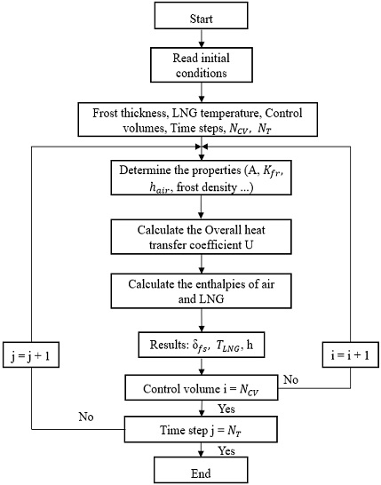
The total heat flux is influenced by the enthalpy of LNG, because the sensible heat and latent heat are transferred to the natural gas through the frost layer. The enthalpy of air is affected by the sensible heat, which is absorbed by the LNG, and the water vapor condenses on the frost surface. Figure 1 shows a flowchart of the numerical model.
3. Numerical analysis
In the numerical analysis, the heat transfer models were numerically solved using a 3D MATLAB program, and the two transfer models were numerically solved using MATLAB. Here, the control volume for the calculation was set to 60, and the calculation time was set to 4 h (240 min). In the AAV model, the number of fins was considered in the range of 8-12. The environmental conditions for the calculation were considered for two seasons: summer and winter. For these seasons, the relative humidity values were set to 74.8% and 62%, respectively. The average temperature values were set to 20.9 °C and 0.9 °C, respectively.
The convective heat transfer coefficient influences the calculation of the heat transfer of the AAV; its value was set in the range of 60–80 W/(m2∙K) depending on the force convection conditions. In this study, the forced convection condition was applied for different seasons. Figures 2 and 4 show the LNG temperature graphs, and Figures 3 and 5 indicate the thickness of the frost layer for different convective heat transfer coefficients.
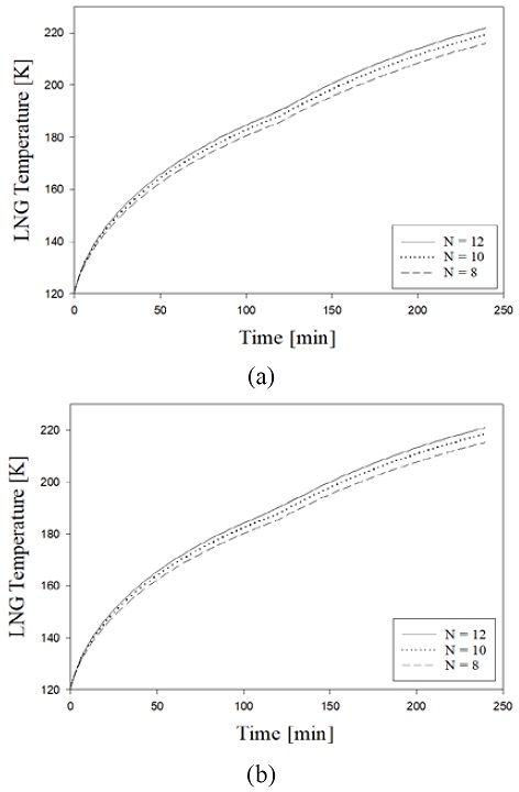
Outlet temperature of LNG in AAV with different number of fins for heat transfer coefficient of 60 W/(m2∙K); (a) Summer, (b) Winter
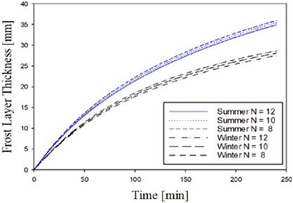
Frost layer thickness in AAV with heat transfer coefficient of 60 W/(m2∙K) for summer and winter seasons
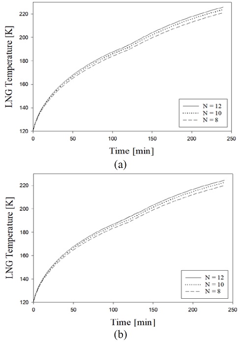
Outlet temperature of LNG in AAV for heat transfer coefficient of 80 W/(m2∙K); (a) Summer, (b) Winter
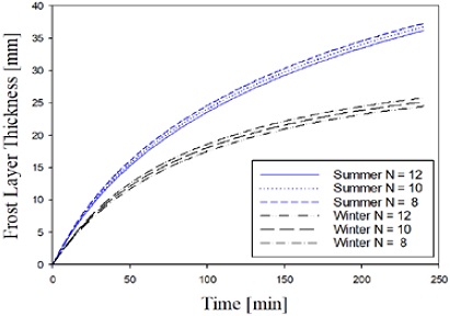
Frost layer thickness in AAV with heat transfer coefficient of 80 W/(m2∙K) for summer and winter seasons
At a heat transfer coefficient of 60 W/(m2∙K), the outlet temperature of the LNG increased with operation time from 120 K to 221 K. As the number of fins increased, the temperature increased rapidly. Regarding the effect of different seasons, the difference in the LNG outlet temperature was in the range of 1-2 K. The temperature difference with the seasonal effect was not significant.
Frost thickness was observed with different operation times; it was found that the frost thickness decreased as the number of fins increased. Regarding the effect of different seasons, the frost thickness increased up to 36 mm and 28.7 mm for the summer and winter seasons, respectively. It was found to differ with different seasons; these results may be due to differences in relative humidity. In the summer season, the maximum relative humidity recorded was 80%, and the humidity affected the growth of frost on the AAV.
At 80 W/(m2∙K), the outlet temperature of LNG increased with operation time from 120 K to 225.88 K. With increase in the number of fins, the temperature increased rapidly. For different seasons, the difference in the outlet temperature of LNG was 2 K. The frost thickness increased up to 37.2 mm and 25.7 mm for summer and winter, respectively.
For the different convective conditions, the outlet temperature of LNG was not influenced by different seasons. However, frost thickness was found to be affected by different seasons.
Acknowledgments
This work was supported by the Regional Innovation Project based on Local Government-University Cooperation [Smart Manufacturing Engineering for Innovation Platform in Gyeongsangnam-do] grant funded by the Ministry of Education [National Research Foundation of Korea (NRF)].
Author Contributions
Conceptualization, S. -W. Lee and S. -W. Choi; Methodology, S. -W. Lee and S. -Y. Jeong; Validation, S. -W. Lee and S. -W. Choi; Investigation, S. -W. Lee; Resources, S. -Y. Jeong; Data Curation, S. -W. Lee; Writing—Original Draft Preparation, S. -W. Lee; Writing—Review & Editing, S. -W. Choi; Visualization, S. -W. Choi; Supervision, S. -W. Choi.
References
- N. J. Kim, C. B. Kim, S. M. Yun, and S. T. Han, “A Study on boiling characteristics of direct contact LNG evaporator,” Proceedings of the Society of Air-conditioning and Refrigerating Engineers of Korea, pp. 380-385, 1994 (in Korean).
-
Y. Lee, J. Park, and C. Han, “Modeling and analysis of frost growth in pilot-scale ambient air vaporizer,” Industrial & Engineering Chemistry Research, vol. 57, no. 17, pp. 5933-5943, 2018 (in Korean).
[https://doi.org/10.1021/acs.iecr.7b03480]

- P. H. Kim, C. P. Kim, H. M. Jeong, H. S. Chung, Y. -H. Lee, “Study on the comparison of heat exchange performance of liquefied gas vaporizer at super low temperature,” Korean Journal of Air-Conditioning and Refrigeration Engineering, vol. 20, no. 10, pp. 679-688, 2008 (in Korean).
-
S. -K. Park and C. Oh, “An experimental study on frost generation mechanism from evaporator tube in air conditioning system,” Journal of Navigation and Port Research, vol. 30, no. 1, pp. 113-117, 2006 (in Korean).
[https://doi.org/10.5394/KINPR.2006.30.1.113]

-
C. J. L. Hermes, R. O. Piucco, J. R. Barbosa Jr., and C. Melo, “A study of frost growth and densification on flat surfaces,” Experimental Thermal and Fluid Science, vol. 33, no. 2, pp. 371-379, 2009.
[https://doi.org/10.1016/j.expthermflusci.2008.10.006]

-
W. -C. Park, C. Y. Song, and O. -G. Na, “Heat transfer characteristics of bulkhead penetration piece for A60 class compartment I: Transient thermal,” Journal of Ocean Engineering and Technology, vol. 32, no. 5, pp. 310-323, 2018 (in Korean).
[https://doi.org/10.26748/KSOE.2018.6.32.5.310]

-
W. -C. Park and C. Y. Song, “Heat transfer characteristics of bulkhead penetration piece for A60 class compartment II: Fire resistance test for piece material and insulation types,” Journal of Ocean Engineering and Technology, vol. 33, no. 4, pp. 340-349, 2019 (in Korean).
[https://doi.org/10.26748/KSOE.2019.027]

-
J. -H. Kim, et al., “Numerical analysis of unsteady cavitating vortex around two-dimensional wedge-shaped submerged body,” Journal of Ocean Engineering and Technology, vol. 32, no. 1, pp. 36-42, 2018 (in Korean).
[https://doi.org/10.26748/KSOE.2018.2.32.1.036]

-
S. Liu, W. Jiao, and H. Wang, “Three-dimensional numerical analysis of the coupled heat transfer performance of LNG ambient air vaporizer,” Renewable Energy, vol. 87, part 3, pp. 1105-1112, 2016.
[https://doi.org/10.1016/j.renene.2015.08.037]


