
Design of an extremely miniaturized branch-line coupler

Copyright © The Korean Society of Marine Engineering
In this paper, a new size-reduction approach for branch-line coupler is introduced which uses parallel end-shorted coupled lines with lumped capacitors. The characteristic of the new design was analyzed using even-odd mode method, and simulated on HFSS before fabricated on the FR4 epoxy glass cloth copper-clad plat (CCL) PCB substrate at center frequency of 1 GHz. The electrical length of transmission line was reduced to 15 degrees, therefore the size of branch-line coupler was largely reduced approximately maintaining the same characteristic around the stable center frequency. The insertion loss of the branch-line coupler filter was –4.39 dB. The size of the overall hybrid is 20 mm × 20 mm. Measurements results were well agreed with the simulated ones.
Keywords:
Stable center frequency, Miniaturization branch-line coupler, Coupled line, Electrical length1. Introduction
The branch-line coupler is a type of quadrature coupler, and is widely used in various kinds of circuits and systems as a basic component, such as balanced mixer, power divider, etc. The circuits usually occupy large area and take high cost to realize due to the long length of the quarter transmission line that constitutes the coupler. There have been several methods applied to realize the miniaturization of branch-line couplers so far. One representative approach was lumped elements method [1], However, the bandpass of the circuit was relatively narrow, and the design becomes difficult at frequencies above 20 GHz. Another size reduction method proposed by Hirota [2] was attractive in view of using short transmission line and lumped capacitors. But the circuit size could not be much reduced due to the limitation of the high impedance of the transmission line.
In this paper, a new size-reduction approach for brach-line coupler is introduced which uses parallel end-shorted coupled lines with lumped capacitors on the foundation of lumped elements method. With this method, the length of the transmission line can be reduced to 1/6 of λ/4 transmission line, therefore, the size of the new branch-line coupler become much smaller without sacrificing the characteristics of the conventional branch-line coupler at the operating frequency.
2. An extremely miniaturized branch-line coupler
2.1 Conventional branch-line coupler
A conventional branch-line coupler consists of four quarter-wavelength transmission lines as shown in Figure 1, at a center frequency. Characteristic impedances of the ports are 50 Ω, Power entering port 1 is evenly divided between ports 2 and 3, power 4 is isolated port, and there is a 90 degree phase shift between port 2 and 3.

Conventional branch-line coupler circuit
2.2 Size-reduced branch-line coupler
The branch-line coupler consists of four λ/4 transmission lines, so in order to miniaturize the branch-line circuit, the length of the λ/4 transmission lines need to be reduced. The size-reduction of quarter-wavelength transmission line is done here through a series of equivalent circuit transformation.
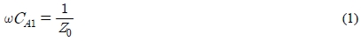
As is well known, the quarter-wavelength transmission line also can be made equivalent to a lumped circuit, as given in Figure 2 (b), and the value of CA1 is given by

Quarter-wavelength transmission line (a), capacitively loaded transmission line (b), reduced capacitive load line with shunt resonant circuits (c), parallel end shorted coupled line (d)
By replacing the lumped inductor, the lumped circuit can be transformed into an equivalent circuit with artificial resonance circuits inserted as shown in Figure 2 (c), furthermore the dotted network can be made equivalent to the parallel end shorted coupled line section with electrical length of θA, and the final equivalent circuit is shown in Figure 2 (c), The related formulas are expressed by [3]
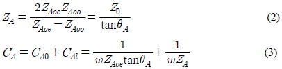
Where ZA and Z0 are the characteristic impedances of the shorted coupled lines and characteristic impedance of the quarter transmission line. θA and ω are the electrical length of the shorted line and angular frequency, respectively. CA is the combination of CA0 and CA1. Zoe and Zoo are the even and odd mode characteristic impedance of coupled line. When the electrical length θA is very small for compact size, ZA becomes very large. This large ZA can be easily achieved by making ZBoe and ZBoo nearly the same.
Figure 3 (a) is a miniaturized branch-line coupler employing the capacitively loaded circuit. The equivalent circuit consisting of parallel end shorted coupled lines is shown in Figure 3 (b).

Reduced size ring hybrid circuit (a), equivalent circuit of ring hybrid with coupled line (b)
Because of the symmetry of the branch-line coupler, we use even-odd mode method to analyse the amplitudes of the emerging wave at each port of the miniaturized branch-line coupler as shown in Figure 4.

Even- and odd-mode decomposition of the ring hybrid when port 1 is excited with a unit amplitude incident wave. (a) Even mode. (b) Odd mode.
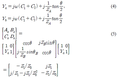
When the amplitudes of the incident waves are 1/2(even-mode excitation), as shown in Figure 4 (a), the magnetic wall is formed at A ㅡ A1. In this case, the circuit is equivalent to an open circuit, as indicated in Figure 4 (a). We multiply the ABCD matrices of each cascade component in the circuit, to give
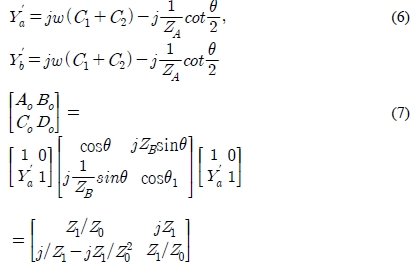
Similarly, when the amplitudes of the incident waves are 1/2 (odd-mode excitation), as shown in Figure 4 (b), the electrical wall is created at A ㅡ A1. In this case, the circuit is equivalent to an short circuit, as indicated in Figure 4 (b),
The reflection and transmission coefficients for the even-and odd-mode of the ring hybrids are given by:
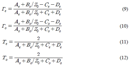
The amplitudes of the scattered waves from the ring hybrid will be:
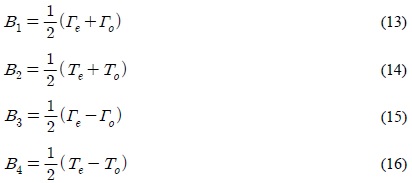
Then with the aid of (9), (10), (11), and (12), according [4] we have:
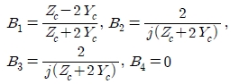
The input port 1 should be matched, so we let B1 = 0, then we can get
 , now the above results turn to be
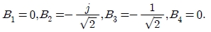
Which shows that the input port is matched, port 4 is isolated, and the input power is evenly divided in phase between ports 2 and 3.
3. Simulations and fabrication
3.1 Simulation Results.
The miniaturized branch-line coupler circuit is designed and simulated on Agilent ADS and Ansoft HFSS before fabrication until we get an ideal simulation result. We designed the miniaturized branch-line coupler circuit by replacing quarter transmission line. Figure 5 shows the structure of the miniaturized branch-line coupler in HFSS. The electrical length θ is 15°. Table 1 gives the design parameters of the HFSS simulation. The parameter values were appropriately tuned for proper simulation results. Figure 6 shows the simulated insertion and return loss responses of the branch-line coupler.

HFSS design

Design parameters of the HFSS simulation

The simulation results of branch-line coupler frequency response and phase shift between port2 and 3
3.2 Measurement Results
The photograph in Figure 8 shows a fabricated branch-line couper with 4 ports, with total die area (including the capsulated ground plane) of 20 mm × 20 mm. It was manufactured on the FR4 epoxy glass cloth copper-clad plat (CCL) PCB substrate having thickness 0.8mm and dielectric constant εr=4.4.

Simulated and measured frequency performance

A photograph of the fabricated branch-line coupler
The measured performances of the coupler at 1GHz is compared as shown in Figure 7. It shows equal power splitting performance and good phase response. The insertion loss of simulation results by HFSS is –3.62 dB and measurement result is –4.39 dB. The measured insertion loss is too lossy because of surface and edge roughness of the metal, inferior metal conductivity, the inexactness of fabrication technology and so on, which can be improved by better craftsmanship. The branch-line coupler operating at 1 GHz exhibits a band width of 130MHz and 90o ± 6o degree phase difference.
4. Conclusion
A miniaturized branch-line coupler at 1.0 GHz was realized using parallel end shorted coupled lines. The electrical length of the coupled lines were reduced to 15 degree, and the size of the overall coupler is 20 mm × 20 mm, representing an 98% savings over a conventional branch-line coupler. The measurement results agreed well with simulation curves. The relatively stable center frequency and acceptable insertion loss make this design suitable to be used in microwave integrated circuits.
Notes
References
- Y. C. Chiang, and C. Y. Chen, “Design of a wide-band lumped-element 3-dB quadrature coupler”, IEEE Transactions Microwave Theory Technic, 49(3), p476-479, (2001).
- T. Hirota, “Reduced-size branch-line and rat-race hybrids for uniplanar MMIC’s", IEEE Transactions .Microwave Theory Technic, 38(3), p270-275, (1990).
- I. Kang, and J. S. Park, “A reduced-size power divider using the coupled line equivalent to a lumped inductor”, Journal of Microwave, 46(7), p82-88, (2003).
- D. M. Pozar, Microwave Engineering, Wiley, New York, (1998).