Effect of pre-post injection timing of diesel fuel for naval vessel on the combustion and emission characteristics in an optically-accessible single cylinder diesel engine
The objective of this study is focused on the analyzing combustion, carbon monoxide and hydrocarbon emission characteristics of marine diesel oil, utilized for naval propulsion engine, with varying pre-post injection timing of an optically accessible single cylinder engine. And also the combustion process is analyzed by means of a high speed camera visualization. On the result of retarding pre-injection timing toward main injection timing, the mean effective pressure and maximum pressure of combustion chamber are increased; however, the heat release rate is decreased. Furthermore, the emission rates of carbon monoxide and hydrocarbon are reduced in this case. In hence, when a post-injection timing is advanced, the mean effective pressure and maximum pressure are increased, because the combustion has been performed under the high temperature and high pressurized environment during main injection time, and the emission rates of carbon monoxide and hydrocarbon are increased. From the experimental results, it considered that retarding of pre-injection timing affects to shorten the ignition delay of main injection clearly, and to raise the flame intensity comparing to the advanced state. The ignition delay during post-injection is not appeared at any post-injection time, but the flame intensity has been weakened gradually according to the retarding of post-injection timing.
초록
본 논문에서는 함정에 탑재된 추진용 엔진에 사용되는 디젤연료(MDO)의 분사상태를 가시화가 가능한 단기통 디젤엔진에 적용시켜 전·후 분사시기에 따른 연소특성, 일산화탄소(CO) 및 탄화수소(HC) 배출특성을 규명하고, 연소과정의 가시화를 통하여 연소특성을 분석하는데 초점을 두었다. 전 분사시기가 주 분사시기 쪽으로 지연될수록 실린더 내부 평균유효압력(Pme) 및 최고압력(Pm)은 상승했으나, 주 분사의 방열율은 저감되고, 일산화탄소 및 탄화수소의 발생량 또한 감소하였다. 후 분사시기가 빨라질 경우 주 분사에 의해 형성된 고온, 고압 하에서 연소가 이루어짐에 따라 실린더 내부 평균유효압력 및 최고압력은 증가하였고, 일산화탄소 및 탄화수소 배출수준 또한 증가하였다. 연소과정을 분석한 결과, 전 분사시기가 늦어질수록 주 분사 시 발생되는 착화지연은 매우 짧아지며, 화염강도는 매우 상승하였다. 분사시기에 관계없이 후 분사 시 착화지연 현상은 발생하지 않았으며, 후 분사시기가 늦어질수록 화염의 강도는 점점 떨어졌다.
Keywords:
Heat release rate, Pre-post injection timing, Carbon monoxide, Hydrocarbon, Ignition delay, 방열율, 전·후 분사시기, 일산화탄소, 탄화수소, 착화지연1. 서 론
디젤엔진에서 연료의 분사시기는 착화지연, 연소과정, 엔진성능 및 유해물질 형성 등에 매우 중요한 역할을 한다. 디젤엔진에 부착되는 전자식 인젝터의 제어기술 발달로 연료의 분사압력은 지속적으로 높아지고, 연료분사 제어기술은 점차 정밀하여지고 있다[1][2].
연료분사시스템에 적용되는 전자제어기술이 발달됨에 따라 디젤엔진의 주 분사에 의해 대부분 결정되는 엔진성능, 유해물질 형성 및 연소조건 등을 개선하기 위하여 전·후 분사방법이 사용되고 있다. 전 분사는 연소실의 온도를 상승시켜 주 분사의 착화지연 및 예혼합(pre-mixture) 연소 시 발생하는 최고 연소온도를 낮추어 준다. 따라서 주 분사 시 생성되는 질소산화물(NOx)의 배출수준 뿐만 아니라 연소효율이 개선되고 소음·진동 등이 저감된다[3]-[5].
후 분사는 주 분사 시 발생된 입자상 물질(PM)을 효과적으로 저감시키기 위하여 사용되는 방법으로 연료분사 시 실린더 내부의 고온·고압상태에서 분사된 연료의 연소와 동시에 혼합조건 개선(enhanced mixing)을 유도하여 주 분사 시 생성된 입자상 물질을 실린더 내부의 잔류산소와 반응을 촉진시켜 유해가스 배출량을 감소시킨다[6]-[8].
본 연구의 목적은 함정용 엔진에 사용되는 디젤유를 가시화가 가능한 단기통 엔진에 적용시켜 전·후 분사시기에 따른 실린더 내 연소특성, 일산화탄소 및 탄화수소 배출특성 및 연소 가시화를 통해 화염의 강도를 포함한 발달과정과 착화특성 등을 분석하는데 있다.
2. 시험장치 및 방법
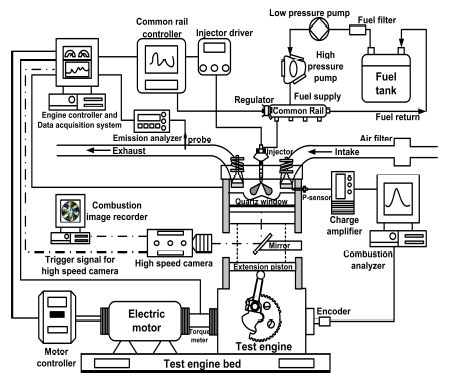
Figure 1은 함정에 탑재된 추진 및 발전용 엔진에 사용되는 디젤유를 연소 가시화가 가능한 단기통 디젤엔진에 공급할 때 전·후 분사시기가 연소 및 배기 특성에 어떠한 영향을 미치는지를 분석하기 위한 시험장치의 구성을 나타낸 것이다.
함정에서 사용하는 디젤유의 유황분 함량은 0.025wt%로 자동차용 디젤유 보다는 높지만, 민수선박에 사용되는 디젤유(MDO) 보다는 낮다. 함정 추진 및 발전용 엔진에 사용되는 디젤유의 주요 물성치를 Table 1에 나타내었다.
시험장치는 축압식 연료분사형(common rail) 단기통 디젤엔진, 연료공급시스템, 시험엔진의 회전수를 정밀제어하는 22kW급 전동기, 분사압력 및 분사시기를 제어하는 제어장치, 냉각시스템, 연소 특성분석(1,000cycle 평균화)을 위한 연소해석장치(Mobiltek MT-7002S), 배기가스 배출물 특성분석을 위한 배기가스 분석장치(Testo 350K), 연소 가시화를 위한 가시화시스템 등으로 구성되어 있으며, 시험엔진의 사양 및 시험조건은 Table 2에 나타내었다. 또한, 연료분사시기에 따른 연소특성을 파악하기 위하여 신호증폭장치(Kistler, 5018)와 연결된 예열 플러그식 압전소자(piezoelectric) 연소압력센서(Kistler, 6056A )를 장착하였고, 연소가시화를 위해 석영 확대경(quartz window)을 부착한 피스톤과 초고속 카메라를 이용하여 연소과정을 촬영할 수 있는 가시화 시스템을 구성하였다.
엔진 회전수는 공회전 상태인 800rpm으로 설정하여 시험을 진행하였고, 연료분사압력(Pinj)은 30MPa, 연료의 전 분사기간(PDinj)은 0.6ms, 주 분사기간(MDinj)은 1.0ms, 후 분사기간(PODinj)은 0.6ms로 고정시켰다. .
연료의 주 분사시기(MTinj)는 BTDC 5o로 고정하였고, 전 분사시기(PTinj)는 BTDC 30o에서 BTDC 15o까지, 후 분사시기는 ATDC 5o에서 ATDC 20o까지 5o간격으로 각각 변경하면서 전·후 분사시기가 연소 및 배기가스의 유해성분 배출특성에 미치는 영향을 분석하였다.
초고속 카메라를 이용하여 연소과정 촬영 시 프레임속도(frame rate)와 셔터속도(shutter speed)는 16,000fps 및 1/32,000초로 각각 설정하였고, 연료분사신호와 동기화시켜 촬영하였다. 주요 시험장치의 사양은 Table 3에 보이는 바와 같다.
3. 시험결과 및 고찰
3.1 연소특성
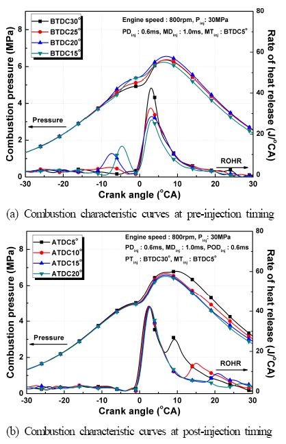
Figure 2는 연료의 전·후 분사시기가 실린더 내부 압력 및 방열율에 미치는 영향을 나타낸 결과이다. Figure 2(a)의 경우 전 분사시기가 주 분사시기 쪽으로 지각됨에 따라 실린더 내부 압력이 높아지는 현상을 확인 할 수 있으며, 실린더 내부의 최고압력은 전 분사시기가 BTDC 20o일 때 가장 높았다. 그러나 전 분사시기가 주 분사시기와 가장 근접한 BTDC 15o에서는 오히려 실린더 내부 최고압력이 낮아지는 결과를 초래했다.
전 분사시기가 지각될수록 전 분사 시 발생한 방열율은 높아지는 현상을 보이고 있으나, 주 분사 시 발생하는 방열율은 저감되는 결과로 분석되었다. 방열율을 결정하는 중요한 요소는 예혼합 연소의 강도인데, 전 분사시기가 BTDC 30o인 경우 주 분사가 이루어지기 까지 균일한 혼합기의 형성이 가능하기 때문에 주 분사 시 분사된 연료의 예혼합 연소의 강도는 커지게 되어 방열율이 높다고 판단된다[9]. 그러나 착화시점이 다른 분사시기인 경우에 비해 늦기 때문에 연소압력이 저하된 것으로 판단된다.
시험결과에서 주 분사기기와 가장 근접한 분사각도(BTDC 15o)에서 가장 높은 연소압력과 방열율이 나타날 것이라고 예상했으나, 이미 소량 분사된 연료의 예혼합 연소는 이루어졌고, 주 분사의 연소는 예혼합 연소가 발생되는 조건보다 확산연소조건으로 실린더 내부 환경이 변화되었기 때문에 Figure 2(a)와 같은 결과를 보인다고 판단된다.
Figure 2(b)는 후 분사시기가 연소압력 및 방열율에 미치는 영향을 나타낸 결과이다. 주 분사에서 발생하는 연소압력 및 방열율은 동일하나, 후 분사시기가 ATDC 5o일 때 연소압력과 방열율이 가장 높은 것을 알 수 있다. 후 분사 시기가 늦어질수록 팽창과정에서 이루어지는 연소과정에서의 압력 및 방열율 상승효과가 미미한 것은 엔진 성능에 영향을 미치는 변수라고 판단된다.
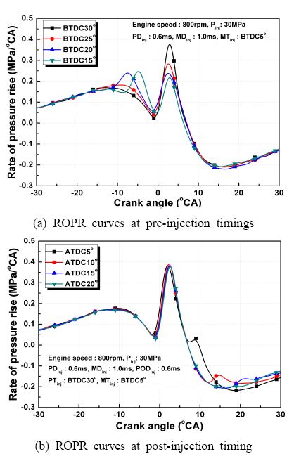
Figure 3은 전·후 분사시기별 크랭크 회전각에 따른 압력 상승률(rate of pressure rise, ROPR)을 나타낸 것이다.
Figure 3(a)의 결과로부터 연소압력 상승률은 전 분사시기가 BTDC 20o일 때 가장 높지만, 주 분사 시 진각상태인 경우보다는 최고압력 상승률이 감소된다. 반면 전 분사시기가 BTDC 30o일 때 주 분사시기의 압력상승율은 가장 낮지만, 다른 분사조건과 비교했을 때 최고압력 상승률이 가장 높은 것을 확인 할 수 있다.
Figure 3(b)의 경우 후 분사는 주 분사시기와 가장 근접한 경우를 제외하고 상승효과는 나타나지 않으며, 가장 근접한 경우라도 그 효과는 미미하다. 이는 팽창행정 중에 일어나는 연소는 압력 상승율에 그다지 영향을 미치지 않음을 알 수 있다.
3.2 배기가스 중 유해물질 배출 특성
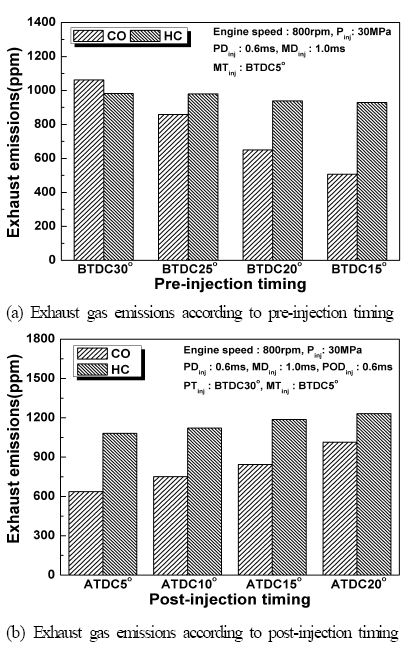
Figure 4는 전·후 분사시기가 일산화탄소 및 탄화수소 배출에 미치는 영향을 나타낸 것이다.
Figure 4(a)의 경우 전 분사시기를 주 분사시기 쪽으로 늦출수록 일산화탄소 및 탄소수소 배출량은 저감된다. 전 분사시기가 늦추어질수록 최고압력은 상승되고, 상대적으로 짧은 예혼합 기간을 가지므로 실린더 내부에 머물러 있는 시간이 짧고 , 주 분사 시 혼합기체의 연소율은 커지게 되어 일산화탄소 및 탄화수소의 배출량이 저감되게 된다.
Figure 4(b)의 경우 후 분사시기가 주 분사시기와 멀어질수록 일산화탄소 및 탄화수소 배출량은 증가한다. 이는 팽창과정에서 실린더에 잔류하는 산소가 지속적인 산화반응에 이용되기 때문에 후 분사시기가 늦추어질수록 연소압력과 연소온도는 낮아지게 되고 분사된 연료는 산소와 반응하기 어려워져서 불완전 연소 및 농후조건(rich condition, λ<1)으로 변하게 되므로 일산화탄소 및 탄화수소 배출량은 증가하게 된다.
3.3 전·후 분사시기의 연소가시화
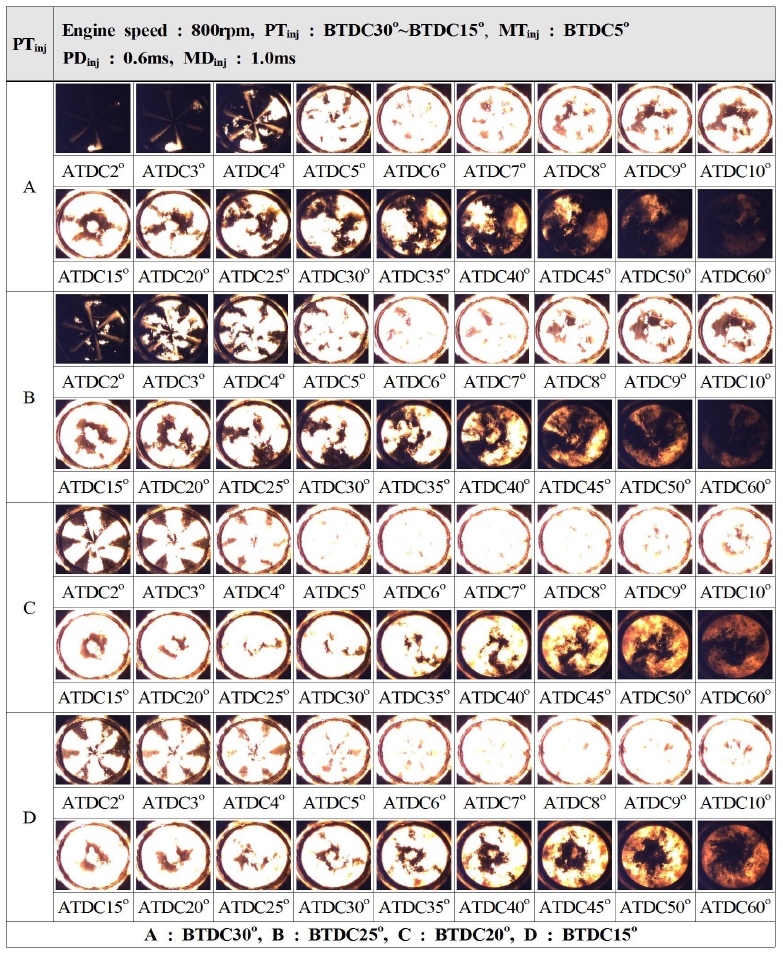
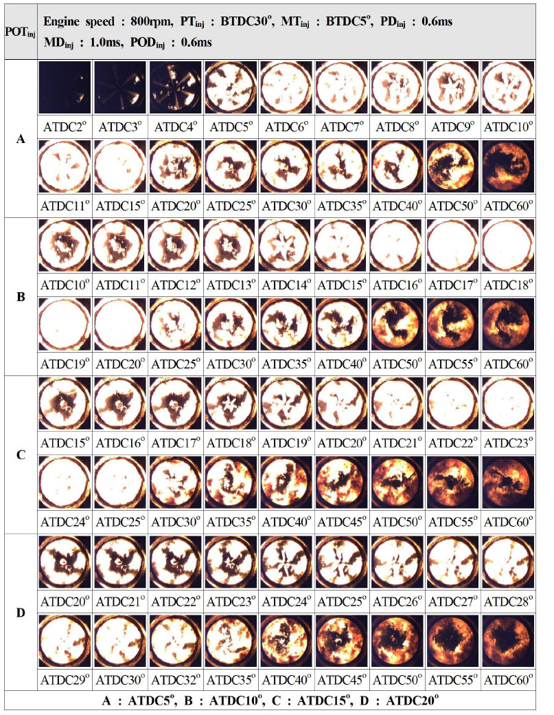
Figure 5는 전 분사시기에 따라 주 분사 시 연소 진행과정을 나타낸 것이다. 전 분사시기가 BTDC30o인 경우 주 분사의 착화시점이 다른 분사각일 때와 비교하면 늦어짐을 알 수 있다. 이는 균일한 혼합기체가 형성되어도 진각상태에서의 혼합기체 농도가 희박하기 때문에 착화가 지연되어 주 분사의 착화지연의 원인이 된다. 그러나 전 분사시기가 늦어질수록 주 분사의 착화는 빨라진다. 특히 ATDC 2°일 때 전 분사시기가 주 분사시기에 근접할수록 점화된 확산화염이 실린더 전반으로 발달한다. 앞에서 설명한 바와 같이 방열율은 예혼합 연소 강도에 의해 크기가 결정되므로 전 분사시기가 주 분사시기에 근접할수록 예혼합 연소보다는 확산화염에 가까운 형상을 가지고 화염이 전파되므로 방열율이 낮아진다. 또한 연소과정에서 확인한 바와 같이 전 분사시기가 늦어질수록 주 분사 연소강도를 증가시켜주기 때문에 화염강도는 커지게 되며, 이는 실린더 내부에서 지속적인 산화율을 촉진시켜, 일산화탄소 및 탄화수소의 저감효과를 가져온다. Figure 6은 주 분사 이후 의 분사시기에 따른 연소 진행과정을 나타낸 것이다. 모든 후 분사시기 조건에서 주 분사 이후 확산된 화염에서 연료유가 분사되어 착화지연 없이 분사와 동시에 화염이 전파되는 현상을 볼 수 있다. 그러나 후 분사이후 화염의 발달강도는 A조건(ATDC 5o)이 가장 우수함을 알 수 있다. 후 분사시기가 늦어질수록 실린더 내부 잔류 산소와의 반응시간이 점점 짧아져 화염의 강도는 약하게 되며, 이는 실린더 내부가 농후조건으로 변하기 때문에 일산화탄소 및 탄화수소의 배출량은 증가하게 된다. 또한, 후 분사 시 화염이 회전하는 확인할 수 있는데, 이는 주 분사 연소 시 화염이 회전하면서 확산된다는 의미이며, 흡기과정에서 흡입되는 공기가 선회류(swirl) 와 와류(tumble) 형상으로 실린더 내부로 유입된다는 것을 의미한다.
4. 결 론
본 연구에서는 함정 주기관 연료로 사용되는 디젤연료를 단기통 엔진에 적용시켜 전·후 분사시기가 연소 및 배기가스 배출물 특성에 미치는 영향과 연소 가시화를 통하여 다음과 같은 결론을 도출하였다.
(1) 전 분사시기가 주 분사시기와 근접할수록 연소압력과 최고압력은 증가하고, 전 분사 시 방열율은 증가되지만, 주 분사의 방열율은 낮아진다. 전 분사시기가 늦어짐에 따라 일산화탄소 및 탄화수소의 발생량은 감소하며, 전 분사시기가 진각상태일 때 연소압력은 다른 분사시기에 비해 낮지만 연소압력 상승률은 가장 높게 나타났다.
(2) 후 분사시기가 주 분사 이후 가장 근접한 경우 후 분사에 의한 연소가 주 분사에 의해 형성된 고온, 고압환경에서 발생됨에 따라 연소압력과 최고압력은 지각조건과 비교했을 때 상승했다. 후 분사시기가 늦어짐에 따라 연소압력 상승효과는 미미하고 일산화탄소 및 탄화수소 발생량은 증가하였다.
(3) 전 분사시기가 지각될수록 주 분사 시 발달하는 화염강도를 크게 하며, 진각상태와 비교할 때 팽창행정 중반에도 화염의 강도는 비교적 큰 것으로 분석되었다. 후 분사시기가 늦어질수록 화염의 강도는 떨어지나 고온의 실린더 내부 환경이 이미 형성되어 분사 시 착화지연은 일어나지 않고 회전하면서 화염이 확산되는 것으로 확인되었다.
Acknowledgments
본 연구(논문)는 해양연구소의 2014년도 정부출연연구비(국고연구)를 지원받아 수행되었다.
References
-
H. M. Lee, “Emission factors based estimation of exhaust emissions with blended fuel from naval propulsive diesel engine”, Journal of the Korean Society of Marine Engineering, 37(4), p332-337, (2013), (in Korean).
[https://doi.org/10.5916/jkosme.2013.37.4.332]

-
H. M. Lee, C. L. Myung, and S. Park, “Experimental investigation of nano-sized particulate matter emission characteristics under engine operating conditions from common rail diesel engine”, Journal of the Korean Society of Marine Engineering, 34(4), p508-514, (2010), (in Korean).
[https://doi.org/10.5916/jkosme.2010.34.4.508]

-
B. Mohan, W. Yang, and S. K. Chou, “Fuel injection strategies for performance improvement and emissions reduction in compression ignition engines-A review”, Renewable and Sustainable Energy Reviews, 28, p664-676, (2013).
[https://doi.org/10.1016/j.rser.2013.08.051]

- M. Özkan, . Özkan, O. Özner, and H. Yılmaz, “Experimental study on energy and exergy analyses of a diesel engine performed with multiple injection strategies: Effect of pre-injection timing”, 53, p21-30, (2013).
- A. Vanegas, H. Won, C. Felsch, M. Gauding, and N. Peters, Experimental Investigation of the Effect of Multiple Injections on Pollutant Formation in a Common-rail DI Diesel Engine, Society of Automotive Engineers Technical Paper2008-01-1191, (2008).
- M. J. Bae, D. S. Han, Y. J. Chang, J. H. Song, and C. H. Jeon, “A numerical study on effects of pilot injection on combustion and emission characteristics in a marine diesel engine”, Journal of the Korean Society of marine Engineering, 34(1), p37-45, (2010), (in Korean).
-
J. Jeong, and O. Lim, “A study on combustion and emission characteristics of diesel-DME blended fuels using pilot injection in DICI engine”, Transaction of Korea Society of Automotive Engineering, 22(4), p55-64, (2014), (in Korean).
[https://doi.org/10.7467/KSAE.2014.22.4.055]

- J. O'Connor, and M. Musculus, Post Injection For Soot Reduction in Diesel Engines: A Review, Society of Automotive Engineers Technical Paper, 2013-01-0917, (2013).
- J. K. Lim, and S. K. Cho, “Effects of fuel injection timing on exhaust emissions characteristics of biodiesel blend oil in diesel engine”, Journal of the Korean Society of Marine Engineering, 36(5), p603-608, (2012), (in Korean).

