Design of a miniaturized monopole antenna for UWB application
Copyright © The Korean Society of Marine Engineering
This is an Open Access article distributed under the terms of the Creative Commons Attribution Non-Commercial License (http://creativecommons.org/licenses/by-nc/3.0), which permits unrestricted non-commercial use, distribution, and reproduction in any medium, provided the original work is properly cited.
Abstract
This paper presents the design of a miniaturized monopole antenna for ultra-wide band (UWB) applications. The proposed antenna consists of a rectangular radiating patch with two cuts at its two lower corners, and a U-shaped ground. Owing to the U-shaped ground and the cuts of the radiating patch, the proposed antenna achieves a wide bandwidth of 2.9~15.3 GHz. Compared to other UWB antennas, the proposed antenna has a smaller size and a simpler structure. In addition, the designed antenna can be easily fabricated on an FR4 substrate.
Keywords:
Monopole antenna, Ultra-wide band, Miniaturization1. Introduction
Antenna designs capable of achieving UWB bandwidth have attracted considerable attention since the Federal Communications Commission (FCC) released an unlicensed 3.1~10.6 GHz frequency band for UWB applications [1]-[3]. In particular, printed monopole antennas have attracted the attention of several researchers over the past few years owing to their physical features such as a simple structure, small size, low cost, and ease of fabrication. Pei-Pei Lu presented a monopole antenna using a radiating patch-shaped ladder structure, for UWB applications [4]. Uprio Kundu presented a UWB antenna by inserting four slots of the same arc radius in four different corners of a rectangular radiating patch [5]. A printed monopole antenna with a tapered and notched radiator designed by Weiwen Li offers a wide bandwidth of 3.07~10.92 GHz [6]. However, the sizes of these antennas are large. An antenna has been designed with W-shape and N-shape slots in the radiating patch that has small dimensions [7]. Another antenna also achieves small dimensions, which was designed by inverting a U-Ring strip and a novel fork-shaped slit to achieve UWB bandwidth [8]. However, these antennas are difficult to fabricate.
In this paper, we present the design of a compact microstrip feed monopole antenna for UWB applications. To achieve UWB bandwidth, we used a U-shaped ground and a rectangular radiating patch with two cuts at its two lower corners. The designed antenna is easy to fabricate. It was fabricated using an FR4 dielectric substrate with a dielectric constant of 4.4 and dimensions of 12 mm × 19 mm × 1.6 mm.
2. Antenna Design
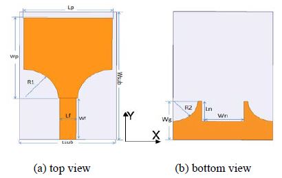
The schematic of the proposed monopole antenna fed by a 50-Ohm microstrip line is shown in Figure 1. The dimensions of the antenna parameters are listed in Table 1.
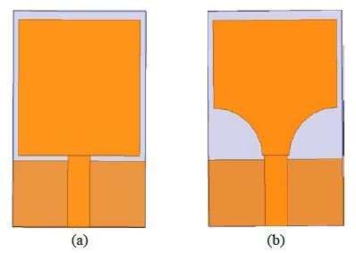
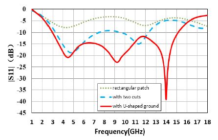
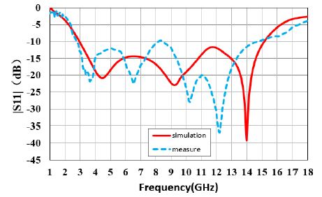
To design the antenna, we first fabricated a basic rectangular patch antenna, as shown in Figure 2 (a). This antenna comprised a rectangular patch with dimensions 11 mm ×12 mm and a ground plane with dimensions 12 mm × 5.8 mm. The basic antenna was modified by inserting two cuts of the same arc radius at the two lower corners of the radiating patch, as shown in Figure 2 (b). From Figure 3, it can be seen that the basic antenna cannot be used as an antenna, as there is no frequency band with |s11|<−10 dB. On the other hand, it can be seen that the antenna with two cuts at the two lower corners of the rectangular patch can provide a wide bandwidth. This phenomenon occurs because the two cuts affect the coupling between the radiating patch and the ground plane. That is, by cutting the lower part of the patch into a curved surface, the change in coupling capacitance can be finely adjusted to increase the impedance bandwidth [9].
However, the antenna with two cuts at the lower corners of the patch cannot sufficiently provide UWB bandwidth. Therefore, we added three cuts on the ground plane to improve bandwidth, as shown in Figure 1 (b). Because the shape of the three-cut ground plane looks like the letter U, we named it U-shaped ground. The U-shaped ground creates a capacitive and inductive load that causes a new resonant, which in turn leads to a change in the bandwidth [10]. Figure 3 shows that the impedance bandwidth of the antenna with the U-shaped ground covers UWB bandwidth from 2.9 GHz to 15.2 GHz.
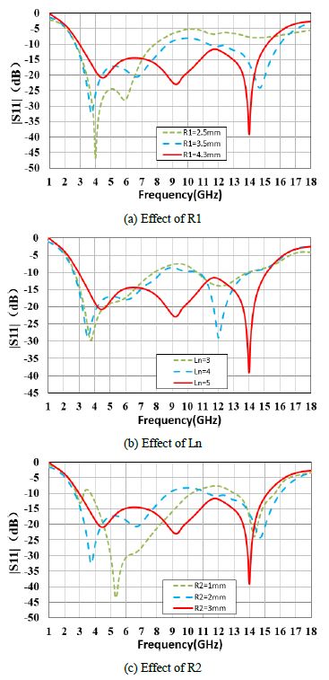
The parameters of the proposed antenna were studied by changing one parameter at a time, while keeping the others fixed. First, we investigated the effect of the parameter R1 on the antenna performance. Figure 4 (a) shows that the larger the cut at the two lower corners of the radiating patch, the better the impedance bandwidth. In this simulation, an optimized value of 4.3 mm for R1 was selected. From Figure 4 (b), it can be seen that the 10 dB impedance bandwidth increases as Ln increases. Figure 4 (c) shows the impedance bandwidth of the proposed antenna for different values of R2. The optimum results were obtained for R2 = 3 mm.
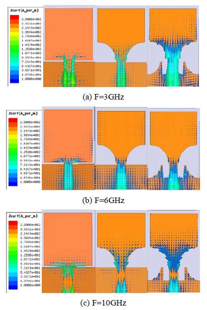
Figure 5 shows the current distributions of the three designed antennas. It can be observed that the current is concentrated in the U-shaped cut edge on the ground plane. In addition, the current near the patch cut has a high density at 3 GHz and 10 GHz. Therefore, the cuts at the two lower corners of the patch have a significant effect at low and high frequencies.
3. Results and Discussion
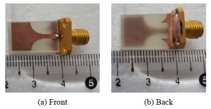
Figure 6 shows a photograph of the fabricated antenna. From this picture, we can see that this antenna is quite small and easy to fabricate. Figure 7 shows the simulated and measured reflection coefficients of the proposed antenna. The measured bandwidth of the proposed antenna is in good agreement with the simulated result, and the fabricated antenna achieves a UWB performance from 2.9 GHz to 15.3 GHz for |s11|<−10 dB.
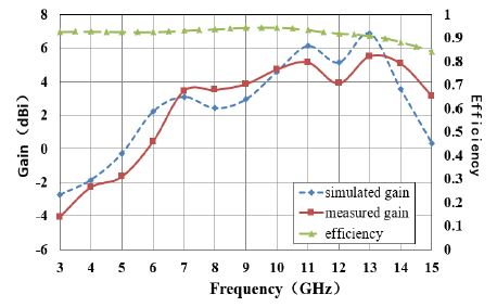
Figure 8 shows the simulated and measured gain, and efficiency of the designed antenna. The measured gain of the antenna varies from -4 dBi to 5.5 dBi within the frequency range of 3 GHz to 15 GHz. The efficiency is approximately 90% in the UWB range. Table 2 shows a comparison of the proposed antenna with other UWB antennas. The proposed antenna has the smallest size and the simplest structure when compared to other antennas with the same function.
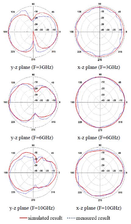
Figure 9 shows the simulated and measured radiation patterns in the E-plane (y-z plane) and H-plane (x-z plane). As current flows in the y-axis direction at all frequencies, as shown in Figure 5, it can be seen that the proposed antenna has an omnidirectional radiation pattern similar to a monopole antenna.
4. Conclusion
A new miniaturized monopole antenna for UWB applications was proposed. With a U-shaped ground and cuts on the radiating patch, the proposed antenna achieved a UWB bandwidth. Moreover, the proposed antenna displayed a good omnidirectional radiation pattern, even at high frequencies. The proposed antenna can be applied to a UWB-RFID tag, and in other fields where UWB application is possible.
Author Contributions
Conceptualization, D. K. Park; Methodology, D. K. Park and J. FangFang; Software, J. FangFang; Formal Analysis, J. FangFang; Investigation, J. FangFang; Writing-Original Draft Preparation, J. FangFang; Writing-Review & Editing, D. K. Park and J. FangFang; Visualization, J. FangFang; Supervision, D. K. Park.
References
- FCC, “Ultra-wideband operation FCC report and order,” US47 CFR Part 15, 2002.
-
Z. N. Chen, T. S. P. See, and X. Qing, “Small printed ultrawideband antenna with reduced ground plane effect,” IEEE Transactions on Antennas and Propagation, vol. 55, no. 2, pp. 383-388, 2007.
[https://doi.org/10.1109/TAP.2006.889823]

-
B. S. Yildirim, B. A. Cetiner, G. Roqueta, and L. Jofre, “Integrated bluetooth and UWB antenna,” IEEE Antennas and Wireless Propagation Letters, vol. 8, pp. 149-152, 2009.
[https://doi.org/10.1109/LAWP.2009.2013371]

- P. -P. Lu, L. -Q. Ma, and Q. Wu, “A 3.0GHz~13.8GHz ultra-wideband planar monopole micro strip antenna,” Proceedings of 2014 3rd Asia-Pacific Conference on Antennas and Propagation, pp. 650-652, 2014.
-
S. Kundu, M. Kundu, and K. Mandal, “Small monopole antenna with corner modified patch for UWB applications,” 2014 First International Conference on Automation, Control, Energy and Systems, pp. 1-3, 2014.
[https://doi.org/10.1109/ACES.2014.6807975]

- W. Li, L. Cai, B. You, and C. Huang, “Design of printed notched-monopole UWB antenna,” 2009 IEEE International Conference on Intelligent Computing and Intelligent Systems, vol. 3, pp. 271-274, 2009.
-
A. Garg, D. Kumar, P. K. Dhaker, and I. B. Sharma, “A novel design dual band-notch small square monopole antenna with enhanced bandwidth for UWB application,” 2015 International Conference on Computer, Communication and Control, pp. 1-5, 2015.
[https://doi.org/10.1109/IC4.2015.7375542]

-
M. Ojaroudi, N. Ojaroudi, and N. Ghadimi, “Dual band-notched small monopole antenna with novel coupled inverted U-ring strip and novel fork-shaped slit for UWB applications,” IEEE Antennas and Wireless Propagation Letters, vol. 12, pp. 182-185, 2013.
[https://doi.org/10.1109/LAWP.2013.2245296]

-
S. -W. Su, K. -L. Wong, and C. L. Tang, “Ultra-wideband square planar monopole antenna for IEEE 802.16a operation in the 2-11 GHz band,” Microwave and Optical Technology Letters, vol. 42, no. 6, pp. 463–466, 2004.
[https://doi.org/10.1002/mop.20337]

-
M. Ojaroudi, C. Ghobadi, and J. Nourinia, “Small square monopole antenna with inverted T-shaped notch in the ground plane for UWB application,” IEEE Antennas and Wireless Propagation Letters, vol. 8, pp. 728-731, 2009.
[https://doi.org/10.1109/LAWP.2009.2025972]

-
S. Bukkawar and V. Ahmed “Omnidirectional and directional fractal UWB monopole antenna,” 2017 International Conference on Nascent Technologies in Engineering, pp. 1-4, 2017.
[https://doi.org/10.1109/ICNTE.2017.7947954]

-
A. Gorai, S. Verma, A. Karmakar, and R. Ghatak, “Sierpinski fractal binomial tapered planar monopole antenna for UWB communication,” 2012 5th International Conference on Computers and Devices for Communication, pp. 1-3, 2012.
[https://doi.org/10.1109/CODEC.2012.6509203]

-
M. M. Sharma, I. B. Sharma, and R. Agarwal, “Circular edge cut diminutive UWB antenna for wireless communications,” 2019 IEEE Indian Conference on Antennas and Propogation, pp. 1-4, 2019.
[https://doi.org/10.1109/InCAP47789.2019.9134555]


