Reduction of structure-borne noise in hydraulic power unit with elastic mounting by evaluating structural acceleration level
Copyright © The Korean Society of Marine Engineering
This is an Open Access article distributed under the terms of the Creative Commons Attribution Non-Commercial License (http://creativecommons.org/licenses/by-nc/3.0), which permits unrestricted non-commercial use, distribution, and reproduction in any medium, provided the original work is properly cited.
Abstract
In naval vessel equipment, airborne and structure-borne noise are ultimately transmitted to the hull and then propagated in water, thus increasing their exposure to the enemy. The noise level is also a critical factor affecting the comfort of crew members. Airborne and structure-borne noise are strictly managed based on US Navy standards, with low vibration and noise as the basic qualities of naval vessel equipment. In this study, the causes of excessive vibration owing to the rotational motion of the motor and reciprocating motion of the hydraulic pump in the hydraulic power unit were analyzed via a structure-borne noise test. A study on reducing the structure-borne noise of the hydraulic power unit is conducted by altering the design of the hydraulic tank. A modal analysis of the hydraulic tank is performed to avoid the frequency that exhibits a high acceleration level in the structure-borne noise evaluation. A harmonic analysis is performed to verify the reduction in structure-borne noise. The effectiveness of the improved design change is verified by confirming that the acceleration level is reduced. Then, the vibration characteristics are identified using finite element analysis (FEA). It is confirmed that FEA is effective in reducing the structure-borne noise in the final test evaluation, thus validating the modified design.
Keywords:
Structure-bone noise, Noise reduction, Harmonic analysis, Hydraulic power unit1. Introduction
1.1 Background of research
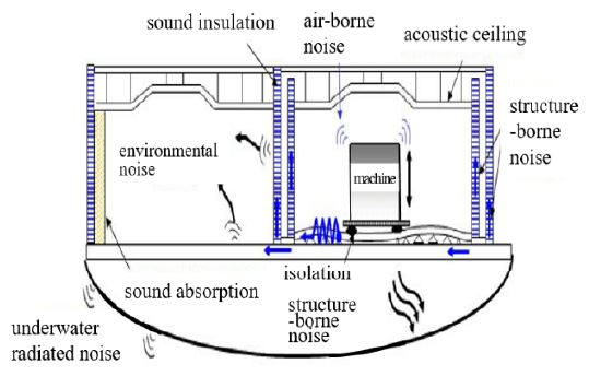
The noise from naval vessels exposes them to the enemy, thus making them vulnerable to attacks from underwater weapon systems such as submarines and torpedoes. Research on vibration and noise reduction in naval vessels is important as it directly affects the survival of the vessels [1]. Noise and vibrations in naval vessels are caused by the equipment installed in the vessel, as shown in Figure 1, and the airborne and structure-borne noise from the vessel are transmitted to the hull and propagated into the water. Such noise and vibration are also very important factors that determine the comfort of crew members [2]. Therefore, in several countries worldwide, the noise level of major compartments is required to be below a certain level. The noise level permitted for major naval vessel equipment is controlled based on more stringent standards for noise in the vessel, as well as for underwater radiation noise. The development and application of soundproof and vibration-proof technology are required to meet these requirements [3]-[6].
For naval vessel equipment, air and structure-borne noise from the equipment must meet US Navy standards [7][8]. Several studies have been conducted on vibration and noise reduction to satisfy this standard. In particular, the hydraulic power unit mounted on naval vessels plays an important role in the operation of various door-closing and opening devices, winches, cranes, and steering systems installed on naval vessels that use high pressure. Because this unit is one of the major causes of noise and vibration in the vessel, low levels of noise and vibration are required.
Recent studies have shown that active mounts combined with passive rubber and electromagnetic actuators have been proposed and applied to marine equipment. In addition, new composite foundations with entangled metal wires have been proposed to reduce vibrations in the foundations [9]-[10]. Furthermore, to address the existing challenges of conventional water piston pumps used in naval vessels, such as low efficiency, high noise, large vibration, and non-intelligent control, a novel type of linear-motor-driven water piston pump has been developed [11]. The exciting forces of naval vessel equipment should be restricted, and additional anti-vibration devices such as resilient mounts and bellows should be applied. Because structure-borne noise depends on the design of the equipment base, the realization of a low-vibration base design is crucial [12]. Electromagnetic devices for vibration damping and isolation are becoming practical alternatives to conventional mechanical vibration and isolation methods [13].
1.2 Objective of research
The hydraulic power unit consists of a vertical motor directly involved in the operation of a vessel. A hydraulic pump installed inside the hydraulic tank is connected to the motor shaft, as shown in Figure 1. A hydraulic tank supporting the motor and hydraulic pump, as well as the inlet and outlet piping, is connected to the pump. An elastic mounting supports the hydraulic tank. The noise in the hydraulic air system is generally classified into airborne and structure-borne noise. Structure-borne noise is generated by the vibration from the operation of the motor and hydraulic pump, which is then transmitted to the structure, causing the structure to vibrate as the noise is transmitted to the hull and propagated underwater.
Structure-borne noise is created by the vibration generated from the rotational and reciprocating motions of the motor and piston of the hydraulic pump, respectively. The source of this noise may be located at the point where vibration is transmitted to the hull through hydraulic tanks, elastic mountings, and piping. There are two approaches to reduce such structure-borne noise. The first approach is to reduce vibrations in the motor and pump themselves, and the second is to control the vibration transmission path and reduce the noise.
This study investigates the cause of excessive vibration created by the vibromotive force of the motor, including the pump itself, in the hydraulic power unit via a structure-borne noise test. A vibration reduction countermeasure is proposed to inhibit frequencies from exceeding the specified vibration level by tweaking the design based on FEA. Modal and harmonic FEA are applied to save time and cost in the experimental approach.
2. Test evaluation of hydraulic power unit
2.2 Evaluation criteria
The evaluation of naval vessel equipment should meet US Navy standards: MIL-STD-740-1 (SH) and MIL-STD-740-2 (SH) [7][8]. The noise specified in US Navy standards is measured by dividing noise into airborne noise delivered through the air and structure-borne noise transmitted through the support at the bottom of the equipment. Separate standards are applied for each type of equipment. Structure-borne noise transmits vibration to the bottom of the hull and connecting equipment, and the noise transmitted to the hull and underwater is evaluated. The vibratory acceleration level is measured at the top of the equipment mount. In the case of equipment vibration, evaluation is performed according to MIL-STD-167-1A, after which the vibration displacement at the rotational frequency is assessed [14].
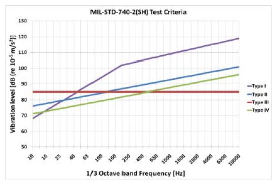
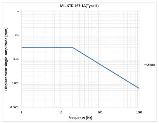
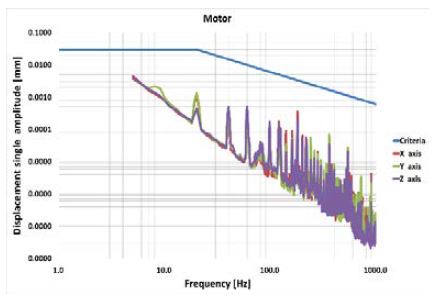
The structure-borne noise in naval vessel equipment is classified into for types: Types I–IV. The Type-II reference level is applied to the hydraulic power unit. The equipment does not come in contact with seawater, and a weighted value of 5 dB is added to the standard level. As shown in Figure 2, the standard level is 1/3 the octave acceleration level with a range of 10–10 000 Hz, and evaluation is performed based on this level. In the case of elastic mounting, the standard level should be less than 11 Hz or less than 1/4 of the operating frequency, whichever is smaller. The vibration measurement test evaluates displacement with a single amplitude in each bearing casing for the rotational equipment. The measuring frequency interval is in the range of 1–1 000 Hz with a 1-Hz interval. The test criteria are summarized in Figure 3.
2.2 Structure-borne noise measurement test
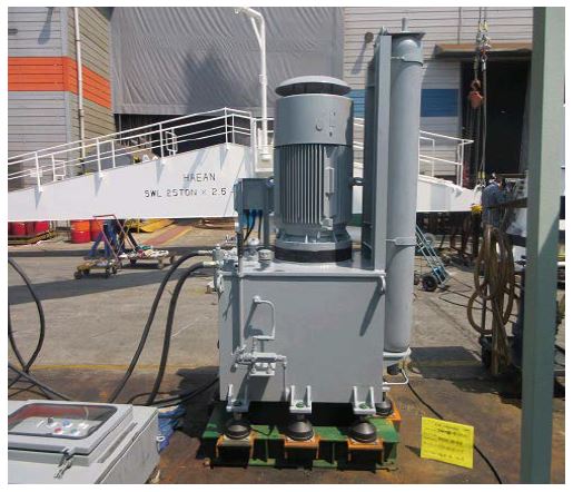
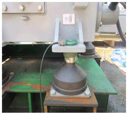
The Type-II reference level required by the US Navy standards is applied in the hydraulic power unit (Figure 4 and Table 1), in which the equipment does not come in contact with seawater and is weighted 5 dB to the reference level. A vibratory accelerometer is attached to the top of the support connected to the bottom elastic mounting of the equipment, as shown in Figure 5.
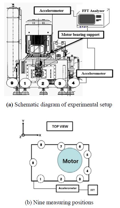
Figure 6 (a) illustrates the experimental setup while the specifications of the acceleration measurement device are presented in Table 2. The measurement frequency range for the 1/3 octave band is from 10 to 10 000 Hz. Considering the number of rotations of the motor and pump, the range for the narrow band is between 1 and 750 Hz. The nine measurement positions are shown in Figure 6 (b).
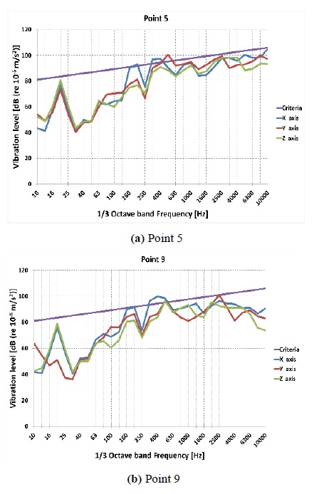
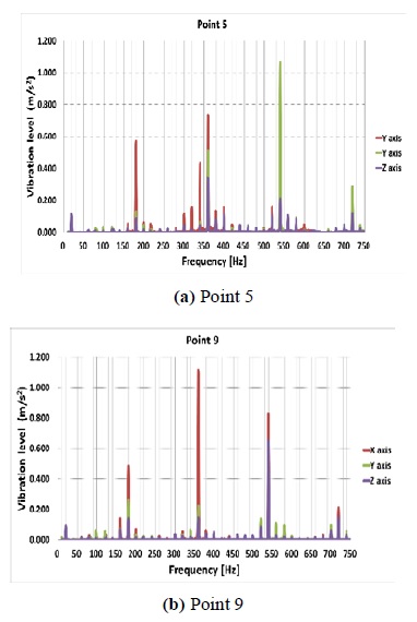
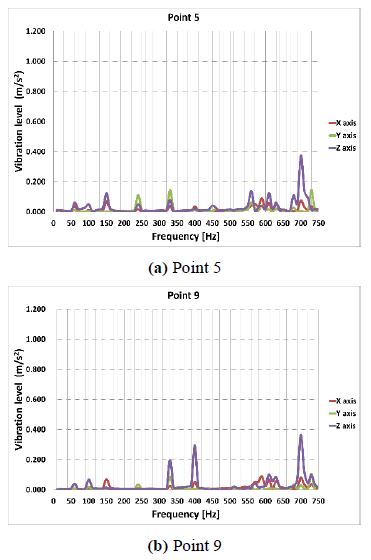
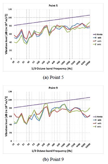
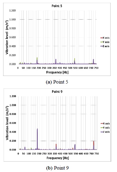
The working conditions include approximately 24 MPa of working pressure and 1170 RPM for the rotation speed of the motor and hydraulic pump. The main specifications are presented in Table 1. The vibration of the hydraulic power unit is generated by the motor and pump. The unit is composed of nine pistons, and the reciprocating motion frequency of the hydraulic pump is 175.5 Hz. Structure-borne noise is measured at the top of the elastic mounting. The results of the structure-borne noise measurement indicate that the vibration level at a particular frequency exceeds the reference level at all measurement positions from positions 1 to 9. Figure 7 shows that the vibration level exceeds the reference level for points 5 and 9.
2.3 Vibration measurement test
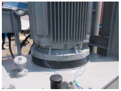
The motor balance and shaft alignment with the bearing were assessed according to the test method of MIL-STD-167-1A. The measurement frequency range is determined from 1 to 1 000 Hz, and considering the frequencies of the hydraulic power unit, the Hanning window function is used with a frequency interval of 1 Hz. The test criteria are shown in Figure 3. The state of the bearing is verified by attaching an acceleration sensor on top of the bearing casing of the motor, as shown in Figure 8. Figure 9 presents a graph of the test results, and it is confirmed that the motor balance and axis alignment are in optimal condition.
2.4 Analysis of structure-borne noise characteristics
The vibromotive force of the vibration generated by the hydraulic power unit is generated by the motor and hydraulic pump. The vibration generated by the rotational and reciprocating motions of the motor and pump, respectively, is transmitted to the entire hydraulic tank, passes through the elastic mounting fixed on the floor, and then transmitted to the hull.
Owing to the structure-borne noise measurement of the hydraulic power unit, all nine measurement positions exceeded the reference level. In the test results presented in Figure 7, the rotational frequency component of the motor exceeds the reference level in the wide band range of 160–10 000 Hz. For a precise analysis, the measurement frequency range was set at 10–750 Hz with an interval of 1 Hz, considering the operating number of rotations of the motor and pump, as well as the frequency band exceeding the reference level. The narrow-band results are shown in Figure 10. In the hydraulic power unit case, the vibration level is appropriate under the no-load operation condition. However, increasing the working pressure triggers local vibrations in the entire hydraulic power unit system, such as in the support connected to the motor and hydraulic pump, hydraulic tank floor, and sides of the unit. Analyzing the narrow band results, the 20-Hz component is the primary component in which the motor rotates, and other frequencies with high acceleration levels are 180, 339, 360, 539, and 719 Hz, five in total. These are the frequencies generated by the reciprocating motion of nine pistons of the hydraulic pump. The frequency with a high acceleration level is considered to be a component generated by the vibration of the surrounding structure from the rotational and reciprocating motions of the motor and hydraulic pump, respectively.
3. Hydraulic tank design considering vibrationcharacteristics
In the narrow-band test results of the initial model of the hydraulic power unit, the main frequency and vibration characteristics are analyzed to reduce the structure-borne noise in the modified model. To perform FEA on the hydraulic power unit, modeling was carried out using the commercially available design program UGS NX 8.0. Modal and harmonic analyses were performed using ANSYS Workbench.
3.1 FEA of initial model
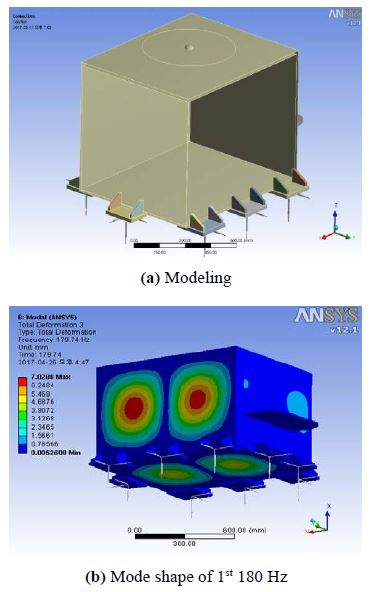
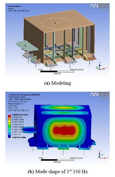
Before developing the design changes, the structure-borne noise characteristics of the hydraulic tank should be analyzed. Figure 11 shows the 3D modeling and first mode of the initial model. The 4-node shell element in ANSYS was used, and the Block Lanczos method was applied to extract the natural frequency and mode shape. The main frequencies obtained from the structure-borne noise test were compared with the natural frequencies obtained from the modal analysis. Owing to this analysis, six existing natural frequencies approximate to the main frequency range obtained from the structure-borne noise test are determined for the initial hydraulic tank. Near the main frequencies, all surfaces, except the upper part of the hydraulic tank, are relatively vulnerable.
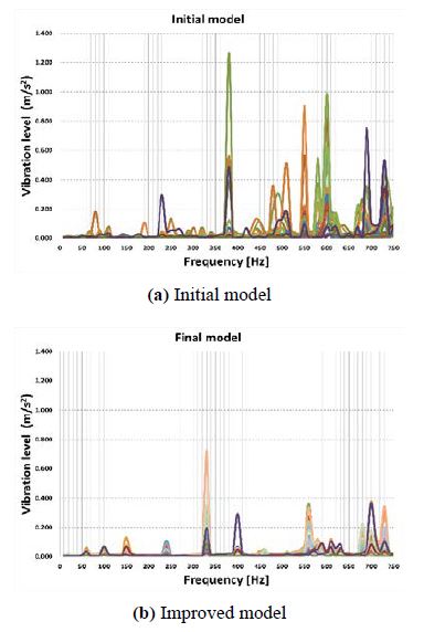
The harmonic analysis results are shown in Figure 12 with high acceleration levels at 380, 550, 598, 689, 732, and 738 Hz. In the actual structure-borne noise test, the acceleration level is determined to be high in the main frequency band (300–500 Hz) range. In the measuring case of point 4, the acceleration level in the vertical direction is high at 380 Hz. From the modal shapes, points of relatively weak spots are identified at the positions of Points 4 and 5 below where the differential pressure regulators are installed.
3.2 FEA of improved model
Figure 13 shows the 3D modeling and first natural frequency of the improved model. To improve the weak points, a 10-mm thick reinforcement is added to the front, rear, side, and bottom of the hydraulic tank, and the structure-borne noise characteristics are analyzed.
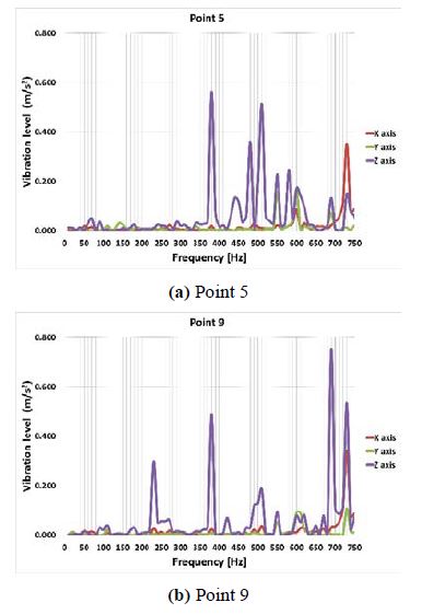
The results of the harmonic analysis after reinforcement are shown in Figure 14, and it can be observed that the acceleration levels are high at 330, 562, 702, and 724 Hz. However, the acceleration levels are reduced, and the number of weak points is reduced compared to the harmonic analysis results of the initial model. After the reinforcement, the weak points disappeared, including the weak points under the differential pressure regulators, which were weak at 599 and 614 Hz. Figure 15 shows a comparison of the vibration level between the initial and improved models.
The design in this study aims to avoid resonance and reduce the acceleration level by isolating the natural frequency inside the hydraulic tank as much as possible from the main frequencies, which are identified in the actual structure-borne noise test.
Compared with the initial model, the improvement effect of the acceleration level in the target main frequency range is significant. Additional reinforcements to the front, side, and bottom surfaces will be effective in reducing structure-borne noise.
3.3 Test results of improved model
Figure 16 presents the test results of structure-borne noise, and at all measurement points from position 1 to measuring position 9, the results obtained satisfy the vibratory acceleration reference level at all frequencies.
The analysis of the narrow band results in Figure 17 demonstrates that all the acceleration levels at the main frequencies generated in the initial test model are reduced.
Some frequencies generated by the piston reciprocating motion of the hydraulic pump still remained, but the results satisfied all of the reference levels provided in the test specifications.
4. Conclusion
This study analyzes the cause of excessive vibration generated by the rotational and reciprocating motions of the motor and hydraulic pump, respectively, in a hydraulic power unit with elastic support, via a structure-borne noise test. Furthermore, to achieve the prevention of resonance and reduce the acceleration levels, a structure-borne noise reduction method for the hydraulic power unit was investigated.
- 1. In the structural-borne noise evaluation of the hydraulic power unit, the frequencies with high acceleration levelsat 180, 339, 360, 539, and 719 Hz, were analyzed. The 20-Hz component is the primary component in which the motor and hydraulic pump rotate, and the 180-, 360-, 539-,and 719-Hz components are the frequencies generated bythe reciprocal motion of the nine pistons in the hydraulicpump. These frequencies occur owing to the vibration ofthe surrounding structure from the reciprocating motion ofthe hydraulic pump.
- 2. The improved model was validated by the reinforcement design of the hydraulic tank to avoid frequency, and it exhibited high acceleration levels in the structure-bornenoise evaluation. A harmonic analysis was performed toverify the effectiveness of the reduction of the structure-borne noise, thus confirming the decrease in the acceleration levels at the main frequencies.
- 3. The implementation of the design change was verified by FEA, which confirmed the effectiveness of reducing structure-borne noise in the final test evaluation.
In this study, FEA was used to save time and cost in the experiment. Furthermore, using the improved model, vibration and noise reduction was achieved in this study in accordance with the US Navy standards.
Author Contributions
Conceptualization, S. -Y. Park; Methodology, S. -Y. Park; Software, S. -Y. Park; Formal Analysis, J. -R. Cho; Investigation, S. -Y. Park and J. -R. Cho; Resources, S. Park; Data curation, S. Park; Writing-Original Draft Preparation, S. -Y. Park; Writing-Review & Editing, S. Park; Visualization, S. -Y. Park; Supervision, J. -R. Cho.
References
-
D. J. Kang, J. H. Gu, and J. W. Lee, “Characteristics of industrial machinery noise,” Transactions of the Korean Society for Noise and Vibration Engineering, vol. 20, no. 2, pp. 160–165, 2010 (in Korean).
[https://doi.org/10.5050/KSNVE.2010.20.2.160]

- H. J. You, E. J. Jung, and J. S. Kim, “A study on the pre-diction of building equipment noise generates at machine room,” Korean Journal of Air-Conditioning and Refrigeration Engineering, vol. 19, no. 6, pp. 476-484, 2007 (in Korean).
- J. S. Kim, H. S. Kim, and S. R. Kim, “Transfer function of structure-borne noise to underwater radiated noise,” Autumn Conference of KSNVE, pp. 138–142, 2001.
- K. Hattori, K. Nakamachi, and M. Sanada. “Prediction of underwater sound radiated from ship's hull by using statistical energy analysis,” Internoise-85, vol. 2, pp. 645–648, 1985.
- S. S. Kim, D. S. Cho, and H. I. Ahn, and S. M. Chung, “Optimal adherent position of viscoelastic material for the reduction of sound power radiated from the stiffened plate,” Journal of Ocean Engineering and Technology, vol. 12, no. 2, pp. 22–32, 1998 (in Korean).
-
B. Laulagnet, “Sound radiation by a simply supported unbaffled plate,” The Journal of the Acoustical Society of America, vol. 103, no. 5, pp. 2451–2462, 1998.
[https://doi.org/10.1121/1.422765]

- Department of Defense, “Structureborne Vibratory Acceleration Measurements and Acceptance Criteria of Shipboard Equipment,” USA, MIL-STD-740-2(SH), Dec. 30, 1986.
- Department of Defense, “Air-borne sound Measurements and Acceptance Criteria of Shipboard Equipment,” USA, MIL-STD-740-1(SH), Dec. 30, 1986.
-
Y. H. Shin, S. J. Moon, W. J. Jung, and S. R. Bae, “Experimental approach to active mounts using electromagnetic actuator and rubber with consideration of shock resistance for naval shipboard equipment,” Shock and Vibration, vol. 2019, 2019.
[https://doi.org/10.1155/2019/3958359]

-
Y. Zhu, Y. Wu, H. Bai, Z. Ding, and Y. Shao, “Research on vibration reduction design of foundation with entangled metallic wire material under high temperature,” Shock and Vibration, vol. 2019, 2019.
[https://doi.org/10.1155/2019/7297392]

-
Y. Huang, S. Nie, H. Ji, and S. Nie, “Vibration analysis and experimental research of the linear-motor-driven water piston pump used in the naval ship,” Shock and Vibration, vol. 2016, 2016.
[https://doi.org/10.1155/2016/4608328]

-
H. S. Han, K. H. Lee, and S. H. Park, “Naval-vessel on board equipment base to minimize structure-borne noise,” Journal of Mechanical Science and Technology, vol. 30, no. 12, pp. 5371-5379, 2016.
[https://doi.org/10.1007/s12206-016-1104-7]

-
E. Diez-Jimenez, T. Sugiura, R. Rizzo, M. Gomez-Garcia, and A. Fleming, “Electromagnetic techniques for vibration damping and isolation,” Shock and Vibration, vol. 2019, 2019.
[https://doi.org/10.1155/2019/9139067]

- Department of Defense, “Mechanical Vibrations of Ship-Board Equipment (TYPE I-Environmental and Type II-Internally Excited),” USA, MIL-STD-167-1A, Nov. 2, 2005.
- ANSYS Workbench, 2019.

