Identification of fire resistance characteristics of bulkhead penetration pieces for A-0 class compartment
Copyright © The Korean Society of Marine Engineering
This is an Open Access article distributed under the terms of the Creative Commons Attribution Non-Commercial License (http://creativecommons.org/licenses/by-nc/3.0), which permits unrestricted non-commercial use, distribution, and reproduction in any medium, provided the original work is properly cited.
Abstract
To minimize calamity in the case of a fire on board a ship or in an offshore plant, ship classification societies are strengthening the fire resistance designs for critical ship compartments to keep the blaze from being spread to other compartments. Particularly in critical compartments where structural integrity should be maintained in the case of a fire, such as the A-0 class division, the fire resistance design of a piece passing through a bulkhead compartment is subject to resolution MSC.307(88), which is the international code for application of fire test procedures. This study identified the fire resistance characteristics of an enhanced bulkhead penetration piece designed for an A-0 class compartment using coupled heat transfer and thermal structure analyses based on the finite element method. To verify the numerical analysis results, an actual fire resistance test was carried out in accord with the test procedure prescribed for the MSC regulations.
Keywords:
Fire accident in ship and offshore plant, A-0 class compartment, Bulkhead penetration piece, Coupled heat transfer and thermal structure analyses, Fire resistance test1. Introduction
To protect human life in the case of a fire on board a ship or in an offshore plant and prevent the spread of large-scale damage, most ship classification societies have been strengthening the design regulations regarding fire resistance for critical compartments, such as the cargo hold and accommodations, where flames should not be transmitted from the ignition point. Particularly in critical compartments where structural integrity should be maintained during a fire, such as the A-0 class division, the fire resistance design of a piece passing through a bulkhead compartment is subject to the Safety of Life at Sea (SOLAS) issued by the International Maritime Organization (IMO). To verify the appropriateness of the fire resistance design for an A-0 class bulkhead penetration piece, a fire protection test should be conducted according to the Fire Test Procedure (FTP) specified by the Maritime Safety Committee (MSC). In the FTP code, a series of processes including the design and manufacture of a test specimen mount structure, or structure steel core (SSC), specified in the MSC, assembly of the test specimen and SSC, mounting of the SSC in a furnace, and testing and analysis are described. In addition, a high level of test know-how and significant time and cost are required. To minimize the time and cost needed for the fire test, a numerical analysis that can simulate the FTP code must be conducted.
For ships and offshore plants, a number of studies have been carried out on thermal analysis and fire resistance tests. Barletta et al. conducted a transient heat transfer analysis for cases in which a pipe buried offshore rapidly reached a uniform temperature under start-up working conditions at the same initial temperature as the soil and smoothly reached a uniform temperature [1]. In addition, Zhou et al. conducted a numerical simulation of a heat transfer to analyze the thermodynamic behavior associated with the generation of the cutting access openings in hull structures using the flame cutting method [2]. Murawski conducted numerical analyses for the displacements of both a propulsion system shaft line and a crankshaft occurring from the heat generated by the main low-speed engine mounted on a 3000 TEU container ship [3]. Moreover, Grigonis et al. (2011) conducted fire tests on more than 14 different fire protection coating samples to investigate the relationship between the thickness of the expansion fire protection coating and the heat exposure time [4]. Park and Song also carried out fire tests in accordance with the test procedure prescribed for the MSC regulations, reviewing the fire resistance according to the material type of the bulkhead penetration pieces, such as brass, carbon steel for the machine structure, and austenite stainless steel [5].
When the length of the bulkhead penetration piece is minimized, the relevant work productivity is also significantly improved. However, ship classification societies conservatively specify the length of the bulkhead penetration piece, and if the length is reduced, it is necessary to verify whether the MSC regulation has been satisfied through the FTP code. In this study, an enhanced bulkhead penetration piece design is proposed that reduces the length by more than 70% compared to the classification rules and applies a material with excellent heat transfer characteristics. Through this study, the fire resistance characteristics of the enhanced bulkhead penetration piece design are identified for a A-0 class compartment using a coupled heat transfer and thermal structure analyses based on the finite element method. Both the numerical analysis model and the analysis conditions are generated when considering the same specimen specifications, temperature conditions, and heating time as in the FTP code. Based on a numerical simulation, the results of the temperature distribution are investigated through a transient heat transfer analysis, and the results of the thermal deformation and thermal stress are reviewed by applying the temperature distribution results to the load conditions. To verify the numerical analysis results, an actual fire resistance test is carried out in accord with the FTP code prescribed is the MSC.307(88) regulations. Based on a comparison of the temperature distribution results, the numerical simulation results show good agreement with the fire test results. The enhanced bulkhead penetration piece design for the A-0 class compartment verified in this study can be applied for a reduction in the length of the piece members and to improve the work productivity.
2. Design Review of A-0 Class Bulkhead Penetration Piece
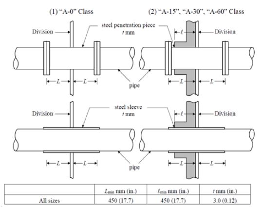
The bulkhead penetration pieces used in ships and offshore plants are applied to the safe installation and operation of various control, monitoring, and communication cables and pipes while maintaining the airtightness of the bulkhead compartment. Figure 1 shows the design specifications of A-class bulkhead penetration pieces.
As shown in Figure 1, ship classification societies and SOLAS require verifying the fire resistance design through fire tests according to the FTP code specified in the MSC. A-0 class bulkhead penetration pieces, made of steel or an equivalent material and having a length of 900 mm or more without insulation, are also designed and installed [7][8].
However, most shipyards fail to comply with the regulations for a length of 900 mm or longer, despite the lack of application of a fire resistance design verified through fire tests according to the FTP code for the design and construction of the A-0 class bulkhead penetration pieces. If a piece length of 900 mm or longer specified by the ship classification society or MSC is applied, deformation of the piece or breakage of the cable will frequently occur during installation or maintenance owing to the excessive piece length, deteriorating the workability.
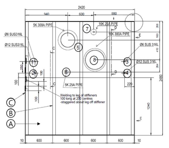
Referring to a previous study, an improved A-0 class bulkhead penetration piece design is proposed herein that reduces the length to 200 mm and applies an austenitic stainless steel (SUS316) material with excellent heat transfer characteristics [5]. The improved A-0 class bulkhead penetration piece design is shown in Figure 2 and Table 1.
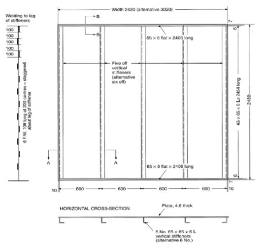
As Figure 2 and Table 1 indicate, the penetration piece tubes are designed as Φ6 and Φ12, and penetration piece pipes are designed as 5K 300A, 5K 25A, 16K 25A, and 16K 300A, respectively. In addition, the lengths of all penetration pieces are 200 mm, and the SUS316 material is applied. To verify the fire resistance performance of the A-0 class bulkhead penetration piece, Figure 3 shows the configuration of the test specimen, i.e., the steel structure core, specified in the FTP code.
As shown in Figures 2 and 3, the bulkhead penetration pieces are installed between the vertical stiffeners of the steel structure core, and a fire resistance test is conducted on a furnace that allows one side of the fire test specimen to be increased to a temperature of approximately 940 °C for 60 min. The adequate fire resistance of the A-0 class bulkhead penetration piece maintaining the structural integrity of the opposite side of the specimen where the flame is applied during the 60-min fire test is specified [8]. This means that the bulkhead penetration pieces should not be damaged or excessively deformed to prevent smoke or flames from propagating through the other compartments during a fire.
3. Coupled heat transfer and thermal structure analyses
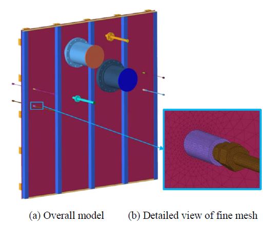
The coupled heat transfer and thermal structure analysis model based on the finite element method for the fire test specimen design in Figure 2 is shown in Figure 4.
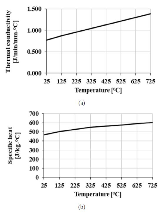
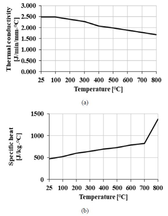
As Figure 4 indicates, the element types of the finite element model are a 4-node linear heat transfer tetrahedron solid for a heat transfer analysis and a 4-node linear tetrahedron solid for a thermal structure analysis. In addition, fine meshing is applied to the parts where the bulkhead penetration piece and the steel structure core are connected. A general-purpose finite element analysis program, MSC.NASTRAN, is used for the coupled heat transfer and thermal structure analyses. The numbers of finite elements and nodes are 765 687 and 221 011, respectively. Material properties such as the thermal conductivity and specific heat for the heat transfer analysis are applied to the values according to the temperature variation by referring to the results of previous studies and are shown in Figures 5 and 6.
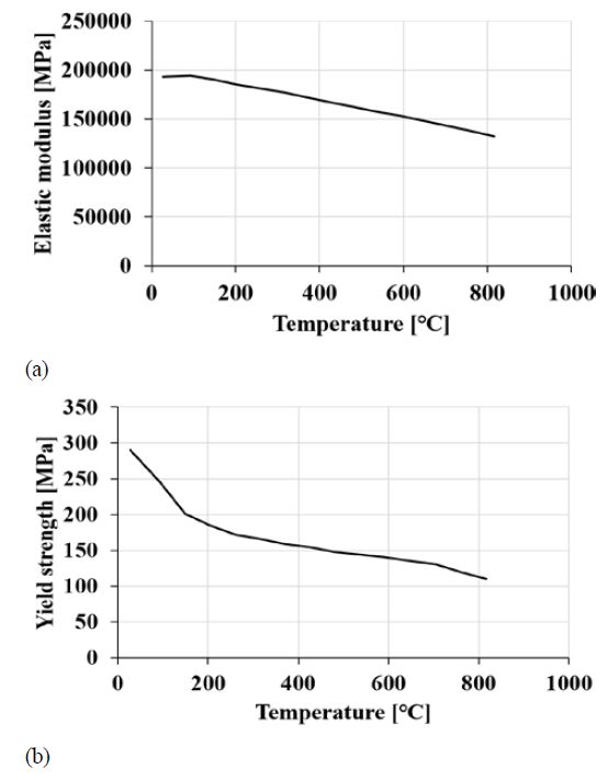
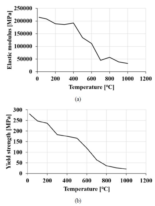
Material properties such as the elastic modulus and yield strength for the thermal structure analysis are applied to the values according to the temperature variation by referring to the results of previous research and are shown in Figures 7 and 8.
The thermal expansion coefficients for SUS316 and SS400 were 2.4E-5 mm/mm/°C and 1.95E-5 mm/mm/°C, respectively. In addition, the ultimate strengths of SUS316 and SS400 were 485 and 540 MPa, respectively.
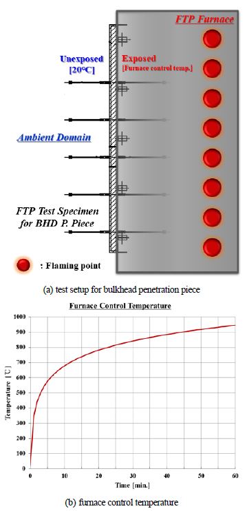
The fire test conditions and the furnace control temperature condition applied to the transient heat transfer analysis are shown in Figure 9.
As shown in Figure 9 (a), in the fire resistance test of the A-0 class bulkhead penetration piece, the specimen is mounted vertically in the furnace, and the internal temperature of the furnace heated from the flame point is adjusted according to the furnace control temperature curve shown in Figure 9 (b) [8]. After 60 min of heating, the structural integrity of the unexposed surface of the A-0 class bulkhead penetration piece should be investigated.
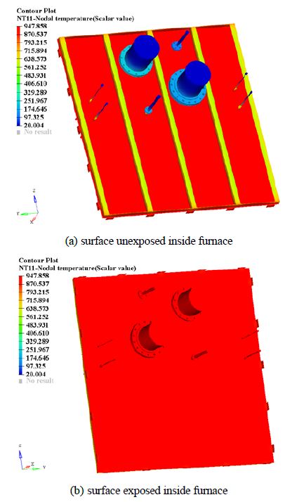
Abaqus/Implicit [11], a general-purpose finite element analysis program, is used to conduct the coupled heat transfer and thermal structure analyses. The temperature distribution is calculated from the transient heat transfer analysis, and the calculated temperature distribution results are mapped to the finite element model for the thermal structure analysis. Figure 10 shows the overall temperature distribution contour results after 60 min of heating.
Figure 10 (a) shows the temperature distribution results of the surface unexposed inside the furnace, depending on the diameter and thickness of the bulkhead penetration piece. The larger the diameter and thickness, the lower the temperature distribution. As shown in Figure 10 (b), the temperature distribution of the surface exposed inside the furnace is increased to the maximum furnace control temperature because the insulation part is not included in the fire test specimen of the A-0 class bulkhead penetration piece. For comparison with the actual test, the detailed temperature results of the heat transfer analysis are measured at the connected points of the bulkhead penetration pieces on the surface unexposed inside the furnace, as shown in Table 1 and Figure 2. The detailed temperature results are summarized in Table 2.
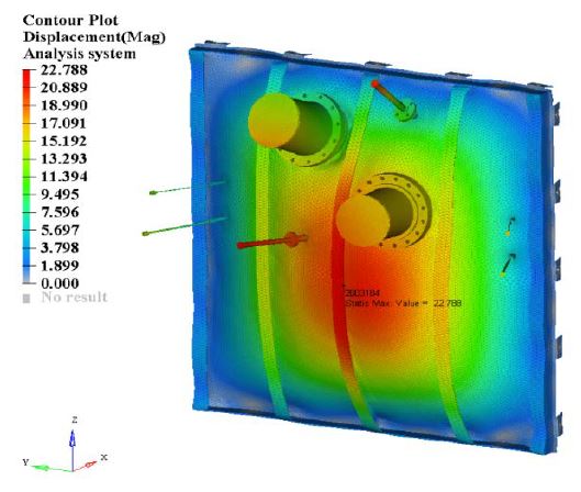
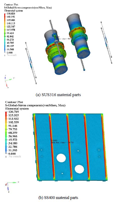
In the thermal structure analysis, the mapped temperature distribution results are used for the load condition, and the fixed boundary conditions are applied to the mount points on the specimen. The thermal deformation and von Mises stress contour results are shown in Figures 11 and 12, respectively.
As shown in Figure 11, the maximum thermal deformation of 22.8 mm occurs at the center of the specimen. As indicated in Figure 12, the maximum stress of the SUS316 part is 198.8 MPa, which is distributed throughout the bulkhead penetration piece of the 5K 25A pipe mounted at the center of the specimen. The maximum stress of the SS400 part is 136.7 MPa, which is distributed on the stiffener at the center of the specimen. Considering that the ultimate strengths of SUS316 and SS400 are 485 and 540 MPa, it was estimated that the structural integrity is guaranteed for the proposed A-0 class bulkhead penetration piece design.
4. Fire Resistance Test
To verify the numerical analysis results, an actual fire resistance test was carried out in accord with the FTP code prescribed in the MSC.307(88) regulations. A vertical fire test furnace, which is used for testing the A-class vertical fire resistance components for ships and offshore plants, requires an effective heating area of 3000 mm × 3000 mm or larger. In addition, the fire resistance is tested by controlling the internal temperature of the furnace based on the test temperature curve in Figure 9 using the burner disposed on the side [12].
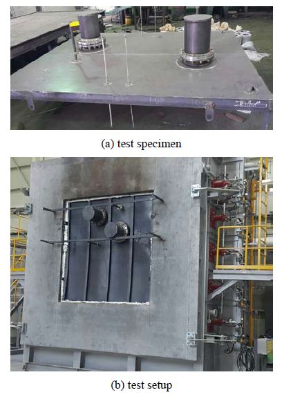
The fire resistance test was carried out at an internationally certified test center. Figure 13 shows the actual manufactured specimen for the fire resistance test and the test setup condition used to conduct the fire test of the proposed A-0 class bulkhead penetration piece design.
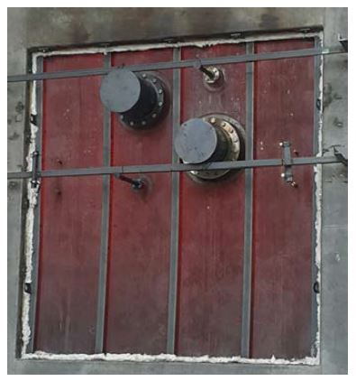
The specimen state and temperature distribution after a 60-min fire test are shown in Figure 14.
The state of the specimen and the temperature distribution shown in Figure 14 are similar to the transient heat transfer analysis results shown in Figure 10 (a). The detailed temperatures are measured at the same points as used in the numerical analysis by applying a non-contact infrared temperature measuring instrument, and the comparison results are summarized in Table 3.
As shown in Table 3, the transient heat transfer analysis results showed good agreement with the test as a whole. The maximum error was less than 16% based on the measurement results at position no. 6. The results also confirm that there no cracks or large deformation occurred after the fire resistance test, and the proposed A-0 class bulkhead penetration piece design satisfies the MSC.307(88) regulation. The coupled heat transfer and thermal structure analyses conducted in this study can be efficiently applied to estimate the fire resistance of an A-0 class bulkhead penetration piece.
5. Conclusion
An enhanced A-0 class bulkhead penetration piece was designed to reduce the length by more than 70% compared to the classification rules and a SUS316 material with excellent heat transfer characteristics was applied. In this study, the fire resistance characteristics of an enhanced A-0 class bulkhead penetration piece were identified using a coupled heat transfer and thermal structure analyses based on the finite element method. In the numerical analysis, the temperature distribution results were reviewed based on a transient heat transfer analysis, and the results of the thermal deformation and thermal stress were calculated by applying the temperature distribution results to the load conditions. From the transient heat transfer analysis, it was found that the temperature distribution results in the surface unexposed inside the furnace were different depending on the diameter and thickness of the bulkhead penetration piece. In the thermal structure analysis, the deformation and von Mises stress results were reviewed, and it was estimated that the structural integrity was guaranteed for the proposed A-0 class bulkhead penetration piece design considering the ultimate material strength. To verify the numerical analysis results, the actual fire resistance test was carried out in accord with the FTP code prescribed in the MSC.307(88) regulation. Based on a comparison of the detailed temperature distribution, the numerical simulation results showed good agreement with the results of the fire resistance test. It was confirmed that there were no cracks or large deformations after the fire resistance test, and the proposed A-0 class bulkhead penetration piece design satisfied the MSC.307(88) regulations. The proposed bulkhead penetration piece design for the A-0 class compartment verified in this study can be properly utilized in terms of a reduction of the piece member and improvements to the work productivity.
Acknowledgments
This research was financially supported by the Ministry of Small and Medium-sized Enterprises (SMEs) and Startups (MSS), Korea, under the “Collabo R&D Program(G21S291073701)” supervised by the Korea Technology and Information Promotion Agency (TIPA).
References
-
A. Barletta, S. Lazzari, E. Zanchini, and A. Terenzi, “Transient heat transfer from an offshore buried pipeline during start-up working conditions,” Heat Transfer Engineering, vol. 29, no. 11, pp. 942-949, 2008.
[https://doi.org/10.1080/01457630802186031]

-
B. Zhou, X. Han, W. Guo, Y. Liu, and S. K. Tan. “Numerical and experimental study on cutting access opening in ship structure,” Journal of Ship Production and Design, vol. 33, no. 1, pp. 12-23, 2017.
[https://doi.org/10.5957/JSPD.33.1.150032]

-
L. Murawski, “Thermal interaction between main engine body and ship hull,” Ocean Engineering, vol. 147, pp. 107-120, 2018.
[https://doi.org/10.1016/j.oceaneng.2017.10.038]

-
M. Grigonis, R. Maciulaitis, and D. Lipinskas, “Fire resistance tests of various fire protective coatings,” Materials Science, vol. 17, no. 1, pp. 93-98, 2011.
[https://doi.org/10.5755/j01.ms.17.1.257]

-
W. C. Park and C. Y. Song, “Heat transfer characteristics of bulkhead penetration piece for A60 class compartment II: Fire resistance test for piece material and insulation types,” Journal of Ocean Engineering and Technology, vol. 33, no. 4, pp. 340-349, 2019 (in Korean).
[https://doi.org/10.26748/KSOE.2019.027]

- ABS, Mobile Offshore Drilling Units - Part 5 Fire and Safety, Rules for Building and Classing, USA, 2018.
- IMO, International Convention for the Safety of Life at Sea, SOLAS 1999/2000 Amendment, UK, 2010.
- MSC (Maritime Safety Committee), Adoption of the International Code for Application of Fire Test Procedures, MSC.307(88), UK, 2010.
- Goodfellow Metals Limited, Metals, Alloys, Compounds, Ceramics, Polymers, and Composites Catalogue, Cambridge, 1993.
-
J. S. Lee and C. Y. Song, “Estimation of submerged-arc welding design parameters using Taguchi method and fuzzy logic,” Proceedings of the Institution of Mechanical Engineers - Part B: Journal of Engineering Manufacture, vol. 227, no. 4, pp. 532-542, 2013.
[https://doi.org/10.1177/0954405413476487]

- Simulia, Abaqus User Manual, Simulia, USA, 2018.
- International Organization for Standardization (ISO), Fire Resistance Tests - Elements of Building Construction, ISO 834-1, Switzerland, 1999.

