Basic study on the design of a power system for characteristic analysis of battery lifetime
Copyright © The Korean Society of Marine Engineering
This is an Open Access article distributed under the terms of the Creative Commons Attribution Non-Commercial License (http://creativecommons.org/licenses/by-nc/3.0), which permits unrestricted non-commercial use, distribution, and reproduction in any medium, provided the original work is properly cited.
Abstract
Recently, there has been an increase in the global awareness on environmental pollution; consequently, there have been moderate attempts to suppress the occurrence of environmental pollutants and ecofriendly transportation with high energy efficiency has been attracting increasing attention. As these ecofriendly transportation systems primarily use batteries, research on battery charging and discharging characteristics is underway to extend the limited life span. In this study, a boost converter used in electric vehicles and electric propulsion ships was installed, and a circuit that can control the discharge current shape between the battery and the load terminal was added to analyze the discharge characteristics of the battery according to the discharge shape. The results of the analysis show that the time required for the state-of-health to reach 80% was small for the waveforms and is in the increasing order of constant current waveform, pulse waveform, sine waveform. This study confirmed that the shape of the discharge current affects the lifetime of the battery.
Keywords:
Battery, Discharge Characteristics, Power System, SOH1. Introduction
Recently, environmental pollution has been attracting attention as a serious problem, and environmental regulations such as reduction of in the production of internal combustion engine cars and reduction of carbon emissions of ships are being implemented worldwide to reduce the emissions of greenhouse gases, air pollutants, and carbon that affect the ozone layer. To satisfy the environmental regulations on air pollutants, research and commercialization of ecofriendly transportation such as electric vehicles and hydrogen fuel cell vehicles are actively progressing. Batteries are used as either the primary or auxiliary power in these transportation systems. Recently, lithium batteries with high energy density have been used and various studies are being conducted on them.
The battery used in ecofriendly transportation can cause rapid charging and discharging owing to long-term operation, rapid acceleration, sudden braking, etc., which can lead to a decrease in battery capacity, resulting in a decrease in battery life. Therefore, a battery management system is significantly important to predict the state and life of the battery by measuring and analyzing current battery characteristic parameters to improve the safety and life of the battery. Therefore, research on methods for measuring and predicting battery parameters such as state-of-charge (SOC) and state-of-health (SOH) and extending battery life is actively being conducted.
In the performance improvement study of the battery, the pulse charging method, which rapidly charges using the current of a pulse waveform, is actively studied [1]. The study on the change in the SOH of the battery due to the pulse charging method can be applied to the pulse discharge process; consequently, a study on the SOH change of the battery owing to the pulse discharge method was conducted [2].
Generally, portable small-capacity electrical devices operate the device by controlling the voltage of the battery through a step-down converter circuit. In this case, the step-down converter itself is affected by pulse discharge in the form of downgrading of the smoothing voltage by controlling the duty ratio. However, the electrical device in the ecofriendly transportation is operated by boosting the voltage of the battery through a step-up converter, in which case the current of the battery flows continuously and is not affected by pulse discharge. In addition, as the discharge of the battery device is determined by the load, it is necessary to control the current waveform in the form of the desired discharge waveform to study the desired type of discharge characteristic.
Therefore, in this study, based on the results of a pervious study that the lifespan is improved when the pulse charge [3] and discharge methods [2] is applied to the battery, a power system circuit capable of controlling the shape of the discharge current was designed to analyze the discharge and lifetime characteristics of the battery. Simulation using the PSIM software was performed and the results were compared by measuring the lifetime state and harmonics of the battery in each discharge by discharging with square, sine, and constant current (CC) waveforms to analyze the discharge characteristics. Based on this, a basic study was conducted to manufacture the actual power system device.
2. Theory
2.1 State-of-health (SOH)
SOH is the lifetime state of the battery and is primarily used as a parameter to estimate the battery lifetime scale. SOH is defined as 100% for the initial unused battery, and when the battery capacity reaches 80% of the initial capacity owing to the continuous charging and discharging of the battery, that is, when SOH reaches 80%, the battery life is defined as the end of the battery [4]. Therefore, reliability of the battery can be increased through the prediction and estimation of the life of the battery, and safety accidents can be prevented.
However, owing to the complex chemical reaction process of the battery, it is difficult to accurately predict SOH; consequently, related ongoing studies are being conducted. Among the methods for estimating SOH, there is a method for estimating SOH based on the consumed capacity of the battery, and it can be expressed as follows [5].
| (1) |
| (2) |
In Equation (1), SOH is represented as a value that is obtained by subtracting the amount of change in the SOH (Equation (2)) from the initial lifetime state, SOH(0) (i.e., 100%). The parameter N indicates the number of charging and discharging cycles to the end of life of the battery, Qnew is the capacity of the initial battery, and Pb is the amount of power used. The above SOH measurement method is calculated by only considering the capacity of the battery; therefore, modeling of the battery is significantly important.
2.2 Recovery effect of battery
The battery used for power supply of the electric device consists of series or parallel connections of several battery cells, and the energy stored in each cell is converted into electrical energy through oxidation and reduction reactions.
As the load current increases, the total charge of the battery decreases. Then, the ratio of the load current to the battery capacity is called the discharge rate. The discharge time of the battery varies according to the discharge rate. As the discharge rate increases, the discharge time becomes faster. In addition, there is a difference in battery usage time in the case of continuous discharge and intermittent discharge, where a pause period is provided in the middle of discharge, while discharging batteries of the same capacity.
When a period of resting is provided during the discharge process, the battery voltage, which was lowered from the existing continuous discharge, increases during the period of rest, resulting in an increase in the capacity of the battery. This is called the recovery effect of the battery.
The reason for the recovery effect is that the electrolyte that exists far from the electrode can stably transfer electrons to the nearby electrolyte during the rest time when the current is not drawn from the battery; consequently, more charges can be drawn from the battery [6].
2.3 Pulse discharge
Pulse control methods include pulse width modulation (PWM) and pulse amplitude modulation (PAM). The PWM method does not change the size of the smoothed DC voltage but changes the output time of the voltage on the pulse to change the equivalent voltage. PAM achieves constant width and cycle of the pulse and changes only its amplitude according to the signal wave.
In this study, pulse discharge was performed using PWM method; moreover, based on the voltage value that was outputted through pulse width control, the output was maintained as a high value for a certain ratio and for the remaining period, the output was a low value to produce a pulse waveform output.
Recently, active studies performed battery discharge in the form of currents such as pulse, triangular, and trapezoidal waves, and the discharge characteristics of batteries were analyzed [7]. Pulse discharge method is a method of discharging pulsed currents at discharge. It was determined that lithium-ion batteries increase the efficiency by approximately 1.3% and discharge capacity by 1.32% when compared to a method with conventional CC discharge [2].
In this paper, based on the pulse discharge study, the influence of the discharge current shape on the characteristics of the battery was analyzed, and a basic study of the power system design was conducted to improve the battery lifetime.
2.4 Total harmonic distortion
Total harmonic distortion (THD) is a measurement of the harmonic distortion present in a signal, defined as the consensus ratio of the forces of all harmonic components to the forces of the basic frequency. It is formulated as follows.
| (3) |
In wireless communication, devices with low THD tend to cause less unintended interference with other electronic devices. As harmonic distortion tends to broaden the frequency spectrum of output emission from the device by adding multiple signals of the input frequency, devices with high THD are not suitable for applications such as spectral sharing and spectral sensing. Low THD in the power system implies low peak current, low heat generation, low electromagnetic emission, and low core loss of the motor.
3. Simulation
3.1 Configuration of the proposed power system
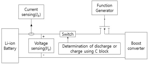
The power system circuit proposed in this paper is illustrated in Figure 1. Figure 1 shows a part of the circuit that can inject any waveform into the battery and a circuit with a step-up converter on the load side. Discharge is performed in the form of a waveform injected into the battery. C block is inserted for the repetition of charging and discharging, and the circuit is designed to charge when the SOC value of the battery reaches 0.3 and discharge when the SOC reaches 0.8. The charge and discharge current amount for charging and discharging had a root mean square (RMS) value of 2 A of discharge current
Existing battery charging/discharging circuits primarily use step-down converters to lower voltages to drive electrical devices. These devices are already applied to the pulse discharge based on the principle of the step-down converter itself; moreover, it is difficult to study the characteristics of the battery according to the discharge waveform. Therefore, in this study, a discharge circuit was designed using a step-up converter. In addition, the output voltage was maintained constant through feedback control for smooth SOH measurement.
3.2 Simulation algorithm
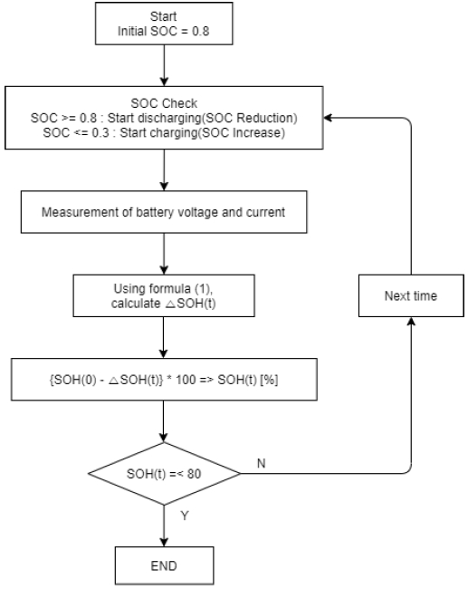
The simulation algorithm is illustrated in Figure 2. Simulation starts from the initial SOC value of 0.8 (80%) of the battery, and the current SOC is checked to start the charging or discharging process. After the start of charging or discharging, the voltage and current of the battery are measured at each sampling time to calculate the power used in Equation (1). After the energy capacity is estimated by using the calculated power, the SOH reduction amount is measured and the current SOH is measured. This is repeated until SOH reaches 80%. When the SOH reaches 80%, the simulation is completed and the results appear in graphs.
3.3 Measurement circuits for SOH
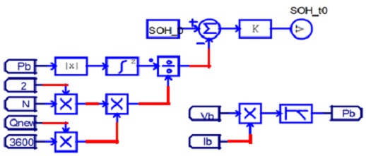
Figure 3 illustrates a circuit for measuring the SOH of the battery; moreover, the SOH measurement algorithm expressed in Equation (1) is designed as a circuit. The voltage and current of the battery are measured and the power value is calculated and then integrated. Then, the integrated value is divided by “2,” “N,” and “Qnew” and the SOH variation is calculated. The SOH variation was subtracted from the initial SOH value and represented as a percentage value.
4. Experiment and consideration
Table 1 lists the initial characteristic value of the lithium-ion battery used in the simulation. To reduce the charging and discharging cycle time, the initial capacity value of the battery was set at 0.01 Ah, and the charging and discharging was performed with a current of approximately 2 A (discharge current RMS value: 2 A) until the battery reached SOH of 80%, which is the time when the battery life is determined to be over.
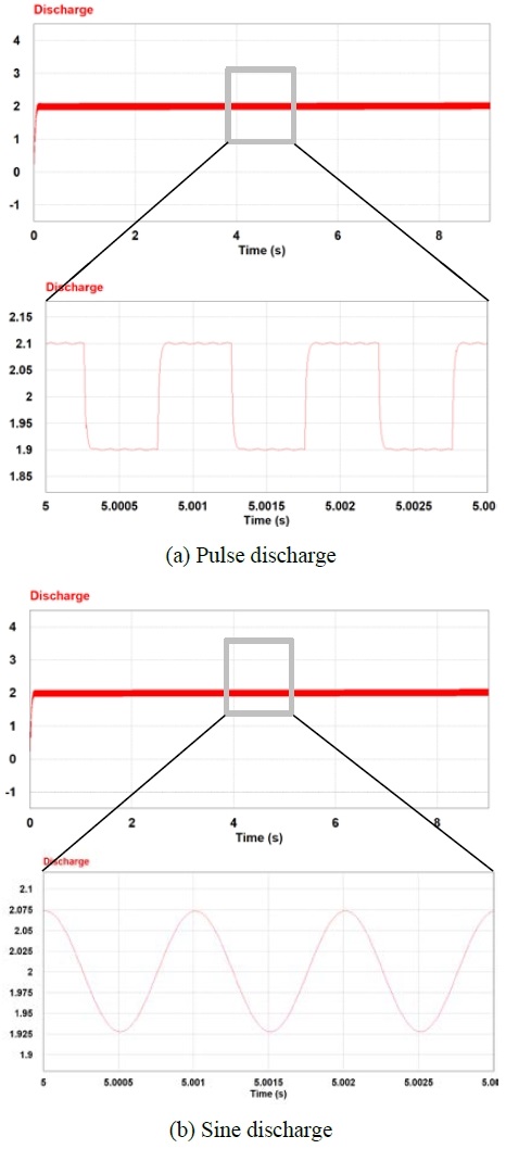
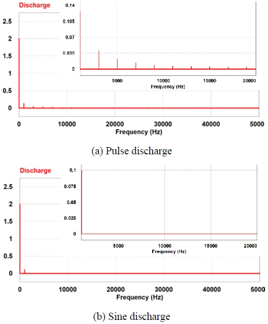
The simulation results show that the battery was charged and discharged 396 times. The initial SOC value of the battery was set at 0.8 (80%) and then the battery was charged and discharged. The lifetime of the battery was compared using the SOH reduction amount shown in the graph. In addition, the THD of the discharge current was measured and compared to investigate the effect of harmonics on the discharge waveform. Figures 4 (a) and (b) show the pulse discharge and sine discharge current graph.
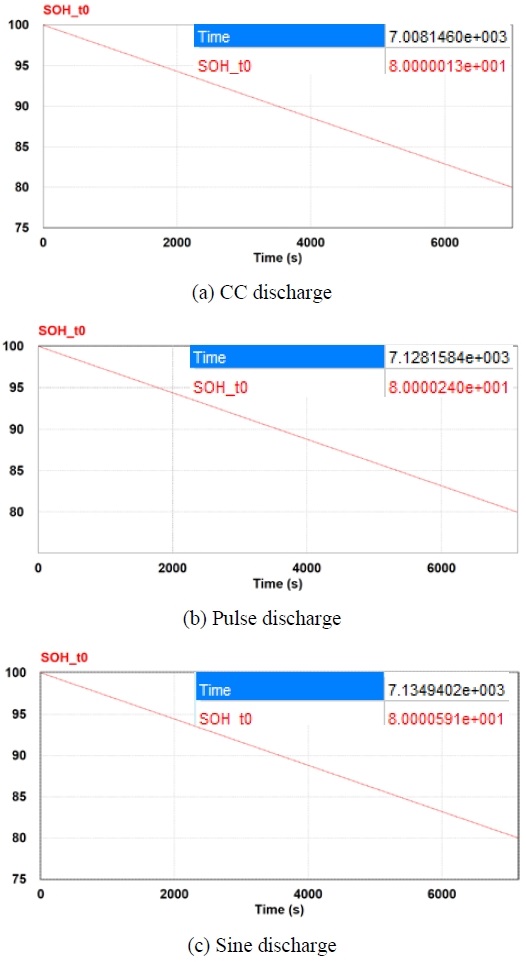
The battery SOH reduction was measured using the SOH measurement algorithm in the proposed power system circuit. The results of the simulation with the three discharge waveforms, i.e., CC, pulse and sine waveforms, are illustrated in Figures 5 (a), (b), and (c), respectively, and the results are listed in Table 2.
Figure 5 illustrates the SOH graph of each discharge. The results of the charging/discharging simulations showed that the time until SOH reached 80% was 7008.1 s in CC discharge, 7128.2 s in pulse discharge, and 7134.9 s in sine discharge. Thus, it was confirmed that CC discharge has the greatest SOH reduction among the three discharge methods, followed by pulse discharge, and sine discharge with the lowest SOH reduction.
Figure 6 illustrates the fast Fourier transform (FFT) graphs of the pulse and sine discharges. The results of the THD calculation using Equation (3) showed that the THD was approximately 0.9m% for the sine discharge and the THD was approximately 44.7% for the pulse discharge.
5. Conclusion
In this research, a basic study was conducted through simulations for the real design of the power system device including improvement function of the battery lifetime. To analyze the discharge characteristics of the battery, the circuit was constructed to control the discharge current determined by the load in a desired form; moreover, CC, sine wave, and pulse discharges were obtained to compare the characteristics of the battery.
The results of the THD measurement in FFT graphs showed that the THD was approximately 44.7% for the pulse discharge and approximately 0.9m% for the sine discharge. The SOH graph results showed that the time required for the SOH to reach 80% was approximately 7008.1 s for CC discharge, approximately 7128.2 s for the pulse discharge, and approximately 7134.9 s for the sine discharge.
The results show that SOH was reduced rapidly in the waveforms and was in the increasing order of CC discharge, pulse discharge, sine discharge, which implies that the battery lifetime was longer and in the decreasing order of sine discharge, pulse discharge, CC discharge. Then, when comparing the relationship between harmonics and SOH, it was confirmed that the decrease in THD and SOH was proportional to the discharge.
The power system device proposed in this study can improve the performance of the battery through the discharge of a specific waveform of the battery, estimate the remaining battery lifetime, and predict the replacement time of the battery through the measured SOH graph. However, in PSIM, the battery model only includes electrical characteristics and the chemical characteristics are not included; therefore, it is likely that an error can exist in the actual model; consequently, further research on accurate modeling is required in the future.
Acknowledgments
This paper is the result of research on the “Leaders in Industry-university Cooperation +” project supported by the Ministry of Education and the Korea Research Foundation and the result of an industrial cluster competitiveness enhancement project supported by the Korea Industrial Complex Corporation, funded by the Ministry of Commerce, Industry and Energy.
Author Contributions
Conceptualization, J. W. Han and S. G. Lee; Methodology, J. W. Han; Software, H. S. Yang; Formal Analysis, J. W. Han; Investigation, J. W. Han; Data curation T. S. Song; Writing-Original Draft Preparation, J. W. Han Writing-Review & Editing, S. G. Lee; Visualization, J. W. Han Supervision, S. G. Lee; Project Administration, S. G. Lee; Funding Acquisition, S. G. Lee.
References
- H. S. Ma, “Battery Management System with High-Reliability for Power Conversion System,” M. S. Thesis, Department of Electrical and Electronic Engineering, Graduate School of Korea Maritime University, Korea, 2017 (in Korean).
-
L. Chen, et al., “Improvement of Li-ion battery discharging performance by pulse and sinusoidal current strategies,” IEEE Trans. Ind. Electron., vol. 60, no. 12, pp. 5620-5628, 2013.
[https://doi.org/10.1109/TIE.2012.2230599]

- T. H. Song, “The Study on the Charge Cycle for Optimization of Battery Pulse Charging,” M. S. Thesis, Department of Electrical and Electronic Engineering, Graduate School of Korea Maritime University, Korea, 2019 (in Korean).
- J. L. Choi, “Study on Electrochemical Impedance Spectroscopy Equipment for Checking State of Battery,” M. S. Thesis, Department of Electrical and Electronic Engineering, Graduate School of Korea Maritime & Ocean University, Korea, 2018 (in Korean).
-
P. O. Hadi and G. Fujita, “Battery charge control by state of health estimation,” Indonesian Journal of Electrical Engineering and Computer Science, vol. 5, no. 3, pp. 508-514, 2017.
[https://doi.org/10.11591/ijeecs.v5.i3.pp508-514]

-
R. Rao, S. Vrudhula, and D. N. Rakhmatov, “Battery models for energy aware system design,” IEEE Computer, vol. 36, no. 12, pp. 77-87, 2003.
[https://doi.org/10.1109/MC.2003.1250886]

-
Y. C. Hsieh, C. S. Moo, T. J. Tsai, and K. S. Ng, “High-frequency discharging characteristics of LiFePO₄ battery,” 2011 6th IEEE Conference on Industrial Electronics and Applications, pp. 953-957, 2011.
[https://doi.org/10.1109/ICIEA.2011.5975724]


