Numerical intact stability evaluation of submerged floating modular habitats
Copyright © The Korean Society of Marine Engineering
This is an Open Access article distributed under the terms of the Creative Commons Attribution Non-Commercial License (http://creativecommons.org/licenses/by-nc/3.0), which permits unrestricted non-commercial use, distribution, and reproduction in any medium, provided the original work is properly cited.
Abstract
In this study, a numerical model of a submerged floating housing system comprising three vertically connected modular ellipsoidal-shaped habitat hulls of different sizes and six symmetrically running tension-leg mooring ropes is theorized using MATLAB and tested for the habitat complex’s hydrodynamic stability using OrcaFlex. The objectives are to design a practicable underwater habitat complex model and evaluate its intact stability against environmental forcings at the nominee offshore installation location near Dokdo island. The stability characteristics of this model underwater housing system, including sufficient buoyancy and angular behavior of each hull as well as their relative displacements between neighboring hulls under acceleration, are investigated with respect to the habitability within the complex.
Keywords:
Habitat, Underwater complex, Underwater housing, Submerged floating housing system, Mooring stability, MATLAB, OrcaFlex1. Introduction
The maritime classification societies of the American Bureau of Shipping (ABS), Det Norske Veritas, Bureau Veritas, and Korean Register recognize the entitlement of compatible submersibles and provide procedural recommendations in design and operation. Meanwhile, other basic engineering standards e.g., the American Society of Mechanical Engineers (ASME) recognize the limitations of materials utilized for any human-occupiable hyperbaric vessel products [1]-[5].
The ranges of recognized submersibles vary among societies although the ABS has acquired the classed units of a fixed habitat and underwater complex on the seabed since 2006. Moreover, owing to heavily populated cities on the world coastlines, the underwater architectural trend is more often found among underwater commercial buildings and ocean observatories. Whereas existing undersea lodges and hotels in tropical waters are getting popularity [6], these facilitated habitable underwater spaces are dependent (of limited autonomy) and open to the earth’s atmosphere at the top floor level to allow fresh air into the immersed section of the buildings, which would extend long beneath the water surface.
To develop an offshore-reliable autonomous underwater housing complex that provides structural simplicity for installation and modular design for scalability, we selected the ellipsoidal hulls of submerged floating modular habitat hulls of different sizes using MATLAB, and tested them with varying modular combinations to investigate their hydrodynamic stability characteristics using OrcaFlex [7]. The assumed installation water depths were set to practicably shallow but to minimize the stability influence of the design wave height to the submerged and vertically combined housing complex, whereas the depth of seabed with six tension-legs fixed on it was assumed to be located sufficiently deep to ignore the reflection and refraction of wave-induced forcings.
2. Design of Submerged Floating Modular Habitat Complex
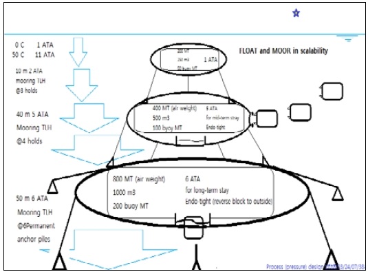
Three individual ellipsoidal hulls were designed with different volumes and buoyancies. They were combined vertically to form three-story habitat complexes while being submerged and floating, as shown in Figure 1.
To limit the objective of this study within the intact stability of these combined habitat complexes, a numerical model comprising modular hulls moored vertically to the piles into the seabed and on the top of the hull underneath was developed. The installed six mooring piles, indicated by larger triangles, on the seabed in Figure 1 were connected to tension legs for the floating habitat hull stack, and assumed to provide no displacement against tension fluctuation during the model simulation. No internal load or external volume change was considered for the housing complex, which was assumed to be self-sustaining with all other necessary capabilities and functionalities. The unknown intact stabilities of the tension-leg-moored hulls were the main concern of the research such that the submerged floating ocean space architecture for potential human occupancy would be confirmed.
The multiple modular ellipsoidal habitats in varying sizes were of the principal semi-axes of 4, 4, and 3 m in the x-, y-, and z-axes, respectively, with the coordinate origin at the center of the ellipsoid for the smallest habitat of nominal 3-man (suggested) occupancy; 6, 6, and 3 m for the medium size of nominal 8-man occupancy, respectively; and 9, 9, and 3 m for the largest of the nominal 20-man occupancy, respectively.
The habitat complex was assumed to be exposed to the differing water pressure corresponding to the installation depths from 1 atmospheric pressure absolute (ATA) up to 6 ATA, where the indoor pressure settings were not directly relevant to the stability of the floating complex. In operational design principles, the smallest habitat hull on the top floor is always maintained at the sea-level indoor pressure setting such that its easy detachment (without decompression) from the remaining floors below before any approaching poor weather guarantees the safety and stability of the remaining system under enhanced environmental forcings.
Two lower habitats were designed to serve a long-term or permanent mission. Moreover, they were designed for serving at wave-sheltered deeper water depths and at near ambient indoor pressure settings that provide benefits of enhanced accessibility to the depth with outdoor excursion. Meanwhile, the increased necessity for decompression to access the water surface requires the habitat hulls to be larger and equipped with a separate pressure-controlled multi-lock air spaces for passenger transit.
Tension-leg mooring system of the habitat complex utilizes multiple numbers of high-modulus polyethylene ropes that run from the mooring piles on the seabed to connect the mooring points on the outer rims of two vertically neighboring habitats, as indicated in Figure 1.
The intact stability of this submerged floating habitat system and the hydrodynamic characteristics of individual habitat hulls were numerically tested by building OrcaFlex models against the maximum weather forcing at the nominee installation location near Dokdo Island, South Korea.
3. Numerical Model
3.1 Model setting
The typical model of these submerged floating habitats comprises three different sizes of ellipsoidal habitat hulls with the nominal volumes of 250, 500, and 1000 m3. The pressure boundaries of the hulls were assumed to be made of HY-100 carbon steel plate, which has a density of 7,748 kg/m3 and a thickness of 10 mm (see Pak S. et al. (2019) for the static model design background) [8].
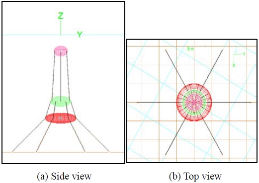
In Figure 2, six symmetrically positioned mooring ropes of 4-inch composite Plasma® 12×12 with a density of 5.86 kg/m3 and minimum tensile strength of 766 metric ton (MT) [9] were used to moor and form the main structural, which were built of three-story floating habitat hulls and connected vertically on the seabed at 70 m water depth. The six mooring piles were assumed as “fixed”-connected, which is one of the connecting options provided by OrcaFlex, reflecting the theory that the mooring piles are connected without any damping or deformation at the connection points. The hexagonal and equidistant seabed mooring points were located at radii R = 20, 30, 40, 50, and 70 m from the projected center on the seabed. The six equidistant mooring points were on a circular path. The mooring radii were varied from the initial design to demonstrate the effects of both mooring angle and applied tension.
The OrcaFlex model shows the global reference frame of the x-axis toward the reader as well as a set of six mooring points located at the uniform radius magnitude, R = 20 m, from which the mooing ropes run to the bottom habitat, named “the 1st floor,” floating at the water depth of 50 m and “fixed” to its six even-spaced symmetric mooring points on the habitat’s wing plane. The same ropes extend continuously to the upper six “fixed” mooring points of the middle habitat, named “the 2nd floor,” floating at the water depth of 40 m. The top habitat was assumed to be installed at a water depth of 20 m by the same mooring ropes extended from the 2nd floor and then connected “fixed.”
The main environmental forcings including the wave heights, wave periods, and current speeds were termed as “mean,” “gust,” and “extreme” weather conditions based on the public domain data collection from the Ulnengdo–Dokdo buoy station located at 37°27′20″N 131°06′52″E by the Korea Hydrographic & Oceanographic Agency, whereas the extreme weather condition was collected from the historical meteorology statistics published by the Korea Meteorological Administration based on the previous data measurements at Ulsan buoy located at 35°20′43″N 129°50′29″E during the passage of Typhoon Maemi in September 2003, as shown in Table 1 [10] [11].

Met-oceanic conditions for numerical model test (uniform direction from negative to positive x-axis applied for current, wave, and wind.)
Each simulation run was categorized into three different strength ranges of mean, gust, and extreme, where “mean” represents the strongest mean among the monthly means measured in 2018, “gust” represents the strongest annual conditions measured in the same year, and “extreme” conditions were obtained from the measured maximums during the passage of Typhoon Maemi in 2003.
Uniform directional orientations of the current, wave, and wind were set parallel to the x-axis during the simulation to yield more apparent forcing outcomes to the stability of the habitat complex. The duration of each model simulation was 3600 s, in which we assumed the full development of a sea state and its effective momentum transfer to the model system, as shown in Figure 2 (a). To identify the precedence of the designed stability enhancers, the OrcaFlex model was categorized and tuned for different loads and environmental forcing schemes as follows.
3.2 Load cases
In terms of the desired density considerations of the housing complex, each habitat hull was designed with two different hull thicknesses of 10 and 100 mm initially (Table 2).
To capture the “self-righting” characteristics of the floating ellipsoidal hulls, the hull types were imposed with three vertical interior equipment loads (equivalent to compensating for 30% of hull displacement buoyancy) distribution scenarios on their lower hemispheres below z = 0, −1, and −2 m. Operational cargo weights including occupants were calculated by considering the weights of the onboard resources of water, food, and personal belongings, as shown in Table 2 [12].
The pre-phase run of the OrcaFlex model for the oblique incoming gust weather 30° to the x-axis inherited the design criteria previously set through MATLAB analysis, in which the hulls were designed to float with near neutral positive buoyancy such that their handling required only minimized lifting or pulling capacity. The result has found that the hulls with small positive buoyancy did not provide sufficient kinematic intact stability to the model. Furthermore, the larger mooring radius or mooring angle at the mooring piles did not secure the floating positions of the habitat complex.
To enhance the hydrodynamic model stability, the initial model was corrected (as shown in Table 3), i.e., for future simulation and analysis, the habitat hull thickness was fixed to 10 mm, which should add buoyancy to the hulls and increase the mooring tension of the habitat complex. Additionally, the length of the mooring radius (R) was fixed to 20 m, and a comparison was shown for the (interior) equipment weight before and after the buoyancy correction, where the increased buoyancies were equivalent to 179 MT for the 1st floor (20-man occupancy) and 27 ton for the 2nd floor (8-man occupancy).
The design of the 3rd floor (3-man occupancy) was based on the operational scheme of a timely and frequent detachment from the lower complex before any expected rough weather. It was designed to maintain a relatively heavier density to enable reduced pulldown capability i.e., the reduction of pulling winches’ tension during its installation or detachment operation [12].
3.3 Equation of motion
The hydrodynamic governing equation of OrcaFlex is the Morison equation, which is expressed as shown in Equation (1). It is fine-tuned for its derivative coefficients, which are the added mass coefficient (Ca) and drag coefficient (Cd), to represent more realistic momentum transfer among the interacting ellipsoidal bodies in the forcing medium [7]. They are summarized in Table 4.
| (1) |
where both the inertia (CmΔar) and drag () components are represented for any mass entity modeled in OrcaFlex.
4. Numerical Test Results
The results of the hydrodynamic stability simulation of the submerged housing complex model installed on the mooring piles, which are located at the mooring radius of R = 20 m, are summarized in Table 5. The column “Floor” indicates the vertical hull stack arrangements under the governing weather scenarios. The resulting magnitude of “Tension” for the same type of floor stack arrangement, in general, increases when the weather becomes stronger. Similar patterns of heavier weather-induced destabilization were observed with the increased values of “Rotation” and “Displacement change.”
The strongest mooring tension 439 MT was predicted for the fully stacked 1st, 2nd, and 3rd floor complexes during gusts. They were all within the range of the minimum tensile strength of the mooring ropes (766 MT), whereas the same floor arrangement against extreme weather was executed with a demobilized 3rd floor based on the operational scheme of the habitat complex.
The stacked 1st and 2nd floor complexes designed for a longer-term mission underwater had similar kinematic response ranges during gusts and extreme weather conditions, although the wave periods and wind speeds had larger discrepancies in terms of magnitude.
5. Analysis
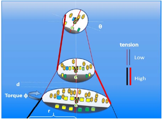
The intact stability assurance is important to the submerged floating structural hulls for maintaining the stable habitability of habitat complex. The measured parameters of the vertically connected floating objects in six degrees of freedom during current- and wave-induced momentum transfer, as illustrated in Figure 3, characterize the hydrodynamic behavior of the designed model system.
The static stability of the model applies the buoyancy parameters of all connected hulls as well as the constraining tensions on the mooring ropes. The dynamic stability applies the transverse parameters, as indicated by “r” and “d”, and the angular motion of the objects, as indicated by “ɸ” and “θ”, respectively, to achieve an instant pseudo-static momentum balance (see Figure 3).
Considering the selected mooring locations R (= 20 m) and the level of displacement “r” for the current habitat complex, the further research and analysis based on a mooring radii larger than 9 m and smaller than 20 m shall justify the sufficiency of the mooring pile arrangement and the measured intact stability outcomes of the current mooring design.
Considering the selected buoyancy level at approximately 30% volumetric water displacement of each habitat hull and the collective tension of the current habitat complex, this buoyancy design is comparable to multiple-stacked flying kites in the atmosphere, where the individual lifting forces of each hydrofoil function collectively as the altitude restoring forces against any vertical pulldown. Further research and analysis that include less than a 30% displacement design scheme shall be tested to justify the sufficiency of the intact stability outcomes of the current submerged floating and stacked hull model.
Considering the righting arm effect of varying vertical load distributions of a modular habitat hull and their collective effect on the stability of the complex, the current model was designed and tested for the opted righting arm lengths shown in Table 6 only in the gust condition.
The center of gravity (CG) of each floor was manipulated by varied interior equipment density distributions in the z-axis. The weight of the designed interior equipment was equivalent to approximately 30% of the water displacement of each corresponding habitat hull and assumed to be distributed uniformly below the set vertical points of Z = 0, −1, and −2 m, as listed in the column “CG_Equipment” in Table 6. Any downward shift in the original CG was the largest at Z = −2 m↓, where the downward arrow “↓” indicates a “uniform density distribution “below” the referenced position. Additionally, we placed the cargo weights, indicated by “CG_Cargo,” at their maximum offset points throughout all load cases to intentionally destabilize the habitat complex system under testing.
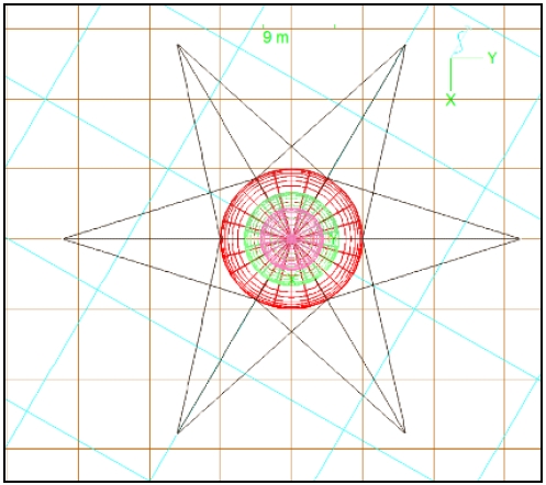
The resulting effect of the increased righting arm however, was less apparent in terms of the predicted rotational behaviors, as shown in the “Maximum θ without Crosslines” column in Table 6. For all the tested load cases, the stability enhancement effect of the crosslines to the 1st floor yielded 18 tension-leg mooring lines between the mooring piles on the seabed and the 1st floor, as shown in Figure 4.
The results with the enhanced stability impact, i.e., approximately 1° of stability improvement for the 2nd floor and the “CG_Equipment” shift from z = − 1 m t o z = − 2 m of the increased length of the righting arm are shown in the “Maximum θ with Crosslines” column in Table 6.
Considering the stability impact of the applied crosslines, the measured maximum mooring tension of 439 MT in the extreme weather condition (see Table 7) was equivalent to 57% of the tensile strength of the assumed mooring ropes, which reduced unnecessary angular momentum-induced tension buildup to the system. Although the parameter for the horizontal torsion (yaw) was not tracked during the current simulation, the stability enhancement impact of the crosslines shall be analyzed in future research. Additional onboard stability enhancement equipment of six smart floats with 1 MT capacity (total 6 MT) were considered and tested for their enhancement impact to the intact stability of the current model state. The floats were assumed to have control-lable buoyancy at any required timing and located at the same “fixed” mooring points on the 1st floor. The stability enhancement impacts of the floats in mooring tension, transverse displacement, and horizontal angular behavior of the 1st floor at the specified hull stack arrangement scenarios are shown in Table 7.
In the “Hull stack arrangement” column, the measurement results of both with and without smart floats indicated by “w” and “wo”, are compared. The overall effect of smart floats in terms of mooring tension reduction was ambiguous, whereas the stability improvement was clear in terms of both the transverse and angular behaviors between from ±0.01 to ±0.21 m and from ±0.05 to ±1.36° respectively.
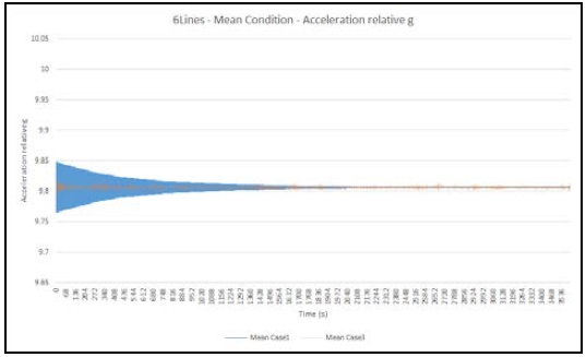
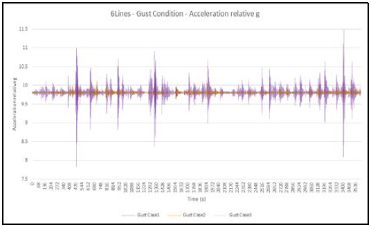
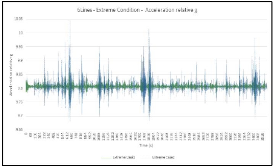
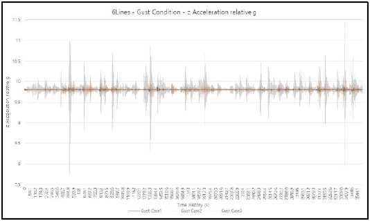
As a proxy of the habitability of the modeled submerged floating underwater living spaces, we considered the overall magnitude of acceleration measured at the CG of the 1st floor. The ranges of fluctuating acceleration, namely “g,” in different weather conditions are listed in Table 8, followed by their time series in Figure 5–7.
In the “Gust” weather condition, the measured acceleration indicates the most destabilized fluctuation range reaching the level equivalent to a 23% reduction or a 17% increment in the gravitational acceleration of g (9.8 m/s2).
In Figure 5, the acceleration time series for the standalone 1st floor (indicated by blue line, Mean Case 1) and the fully stacked 1st, 2nd and 3rd floor habitat complexes (indicated by orange line, Mean Case 3) in the “Mean” weather condition are plotted.
For both cases, the fluctuations of gravity were the largest at the beginning. They began with ±0.05 g and progressively reduced into the midway of the simulation, where both converged near 9.8 m/s2 (fluctuation approached to ±0 g).
In the “Gust” weather condition shown in Figure 6, all scenarios of varying hull stack arrangements show the harmonic returns of local maximums, which indicate the modal change in the kinematic response of the hydrodynamic system with varying acceleration regimes compared with the results of the “Mean” weather. In Figure 6, the measured accelerations in the “Gust” weather condition are plotted. The 1st floor standalone (indicated by gray line, Gust Case 1), the double-stacked 1st and 2nd floor complexes (indicated by orange line, Gust Case 2), and the fully stacked 1st, 2nd, and 3rd floor complexes (indicated by dotted purple line, Gust Case 3) show the range of fluctuation within ±0.23 g.
In the “Extreme” weather condition shown in Figure 7, the harmonic returns of local maximums, similar to the results in the “Gust” weather condition, are identified for the standalone 1st floor (indicated by green line, Extreme Case 1) and the double-stacked 1st and 2nd floor complexes (indicated by blue line, Extreme Case 2). The ranges of fluctuation were within ±0.02 g. This implies that the strongest wind speed of 60 m/s and the wave period of 12.4 s were not the main kinematic driving forces to the system while the remained wave height 11.0 m for both “Gust” and “Extreme” weather conditions is the leading instability factor.
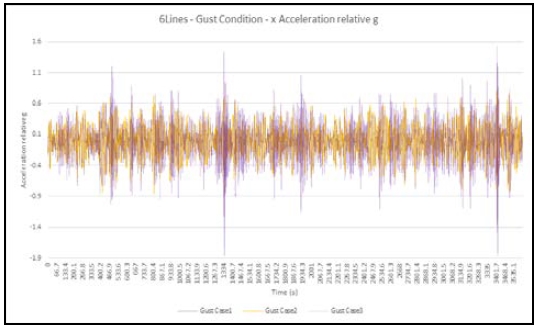
The directional component analyses on the strongest fluctuation of acceleration forecasted during the “Gust” weather condition are shown for the horizontal x-axis component in Figure 8 and the vertical z-axis component in Figure 9.
The horizontal component of the acceleration time series measured at the CG of the standalone 1st floor (indicated by gray line, Gust Case 1), the double-stacked 1st and 2nd floor complexes (indicated by orange line, Gust Case 2), and the fully stacked 1st, 2nd, and 3rd floor complex (indicated by dotted purple line, Gust Case 3) were within the maximum fluctuation range of ±0.19 g (as shown in Figure 8).
The measured values as the proxy of the habitability of the habitat complex under weather forcings are comparable to the longitudinal design force limit of 1.0 g of the ASME or the longitudinal acceleration comfort levels where the passengers of ground transportation may experience a horizontal deceleration up to 0.16 g on a subway coach. In the U.S., the decelerating limitations of similar transit cars are between 0.12 and 0.14 g in the normal braking case, and between 0.14 and 0.30 g in emergency cases [5][13].
On the contrary, the vertical component of the acceleration time series measured at the same location for the standalone 1st floor (indicated by black line, Gust Case 1), the double-stacked 1st and 2nd floor complexes (indicated by dotted orange line, Gust Case 2), and the fully stacked 1st, 2nd, and 3rd floor complexes (indicated by gray line, Gust Case 3) were within the maximum fluctuation range of ±0.23 g (as shown in Figure 9).
The measured values are comparable to the vertical design force limit of 2.0 g of the ASME or the vertical acceleration limit suggested by Rajaraman and Nagaraja (1984), i.e., 0.1 g, as the acceleration and deceleration limits for elevator speed control systems [5][14].
6. Conclusions
Quantitative hydrodynamic responses of the hydrostatic design of submerged floating underwater housing complexes theorized in a previous study by Pak S. et al. (2019) was tested to identify principal design parameters that affect the model complex’s intact stability. These parameters characterize the habitability of such potential habitat designs. The buoyancy structure, density distribution, and varying operational stacking formations were assumed against simplified weather forcings at the nominee installation location near Dokdo Island, South Korea. To classify the required hydrodynamic stability for the submerged floating housing space of permanent occupancy in the future, realistic digital representations must be established based on more specified mandates of the required functionality of the habitat spaces under the corresponding physical and environmental conditions.
Acknowledgments
This research is funded by the program LINC+ of Korean Ministry of Education (ICT integrated Smart Underwater Housing Design Technology, Project No. 2019-E-G034-010109)
Author Contributions
Conceptualization, S. W. Pak; Methodology, S. W. Pak and H. S. Lee; Software, Y. Yim; Formal Analysis, S. W. Pak and Y. Yim; Investigation, S. W. Pak; Resources, H. S. Lee and T. H. Han; Data curation S. W. Pak; Writing-Original Draft Preparation, S. W. Pak; Writing-Review & Editing, T. H. Han; Visualization, Y. Yim and S. W. Pak; Supervision, H. S. Lee; Project Administration, S. W. Pak; Funding Acquisition, H. S. Lee.
References
- American Bureau of Shipping, 2018, “Underwater Vehicles, Systems and Hyperbaric Facilities.”
- Det Norske Veritas and Germanischer Lloyd, 2018, “Rules For Classification, Naval vessels, Part 4 Sub-surface ships, Chapter 1 Submarines,” DNVGL-RU-NAVAL-Pt4.
- Bureau Veritas, 2016, “Rules for the Classification of Naval Submarines.”
- Korean Register of Shipping, 2015, “The Classification of Underwater Vehicles.”
- American Society of Mechanical Engineers, 2016, “Safety Standard for Pressure Vessels for Human Occupancy.”
-
N. Bitterman, “‘Aquatourism’: submerged tourism, a developing area,” Current Issues in Tourism, vol. 17, no. 9, pp. 772-782, 2013.
[https://doi.org/10.1080/13683500.2013.811222]

- Orcina, OrcaFlex Documentation, https://www.orcina.com/resources/documentation/, , Accessed May 1, 2020.
- S. W. Pak, H. S. Lee, and J. Park, “A study on the hydrostatic mooring stability of submerged floating ellipsoidal habitats,” Journal of Korean Navigation and Port Research, vol. 43, no. 5, pp. 328-334, 2019.
- CORTLAND, “Plasma 12x12 Tech Sheet,” https://www.cortlandcompany.com/all-rope/#plasma-12x12, , 2019.
- KOHA, Real-Time Data Ulleungdo(Northeastern) Ocean Buoys, http://www.khoa.go.kr/oceangrid/koofs/eng/observation/obs_real_detail.do?tsType=2&tsId=KG_0101&obsItem=&obsSubItem=S, , Accessed September 14, 2019.
- Korea Meteorological Administration, 2011, “Typhoon White Book 11-1360016-000001-01.”
- S. W. Pak, “Korean Patent”, South Korea, No. KR 102027153, 2019.
- L. L. Hoberock, A Survey of Longitudinal Acceleration Comfort Studies in Ground Transportation Vehicles, RESEARCH REPORT 40, Department of Transportation Office of University Research Washington, D. C., USA, 1976.
-
K. Rajaraman and S. K. Nagaraja, “An elevator speed-control system using squirrel-cage induction motors,” IEEE Transactions on Industrial Electronics, vol. IE-31, no. 2, pp. 164-167, 1984.
[https://doi.org/10.1109/TIE.1984.350063]


