Numerical study on the prediction of the heat dissipation performance of water-cooled cabinets using a fin-tube heat exchanger
 ; Jeong-Hoon Park1
 ; Young-Min Lee2 ; Kwan-Soo Jeon3 ; Myoung-Jun Jeong4 ; Dong-Sup Lee5
Copyright © The Korean Society of Marine Engineering
This is an Open Access article distributed under the terms of the Creative Commons Attribution Non-Commercial License (http://creativecommons.org/licenses/by-nc/3.0), which permits unrestricted non-commercial use, distribution, and reproduction in any medium, provided the original work is properly cited.
Abstract
For the cabinet equipment used in warships, an environmental test that satisfies the MIL-STD-810G standard must be performed. In high-temperature operating tests, thermal design is an important factor because cabinet equipment is operated at high ambient temperatures. In this environment, water cooling is used to ensure the heat dissipation stability of the equipment. In water cooling, cooling water is supplied to the heat exchanger from the outside, and heat from the air inside the equipment is released through the cooling water. In this study, a process for predicting the thermal performance of water-cooled cabinets is established through numerical analysis. The performance of a heat exchanger is predicted using a computational fluid dynamics method and verified experimentally. In addition, the effectiveness changes of a fin-tube heat exchanger with a single pipe are studied based on the direction and flow rate of the cooling water. Using the calculated effectiveness of the heat exchanger, the operating environment of the rack equipment inside the water-cooled cabinet is predicted.
Keywords:
Fin-tube heat exchanger, Water-cooled cabinet, Water cooling system, Effectiveness1. Introduction
Modern warships use equipment with functions for surveillance, reconnaissance, communication, attack, and defense. To perform various tasks, high-performance computers perform a large amount of computations, and these computers are installed in the cabinet equipment in a dense state. For the cabinets used for military purposes, environmental tests that satisfy the MIL-STD-810G specifications should be performed. In high-temperature operating tests, thermal design is an important factor because the equipment is operated at high ambient temperatures. Air cooling and water cooling are used to dissipate heat inside the cabinet. In air-cooled equipment, the air flowing into the equipment is discharged along with heat. In water-cooled cabinets, the internal equipment operates in an enclosed space. Heat transfer is performed between the internal air and the cooling water through a heat exchanger. Furthermore, heat transfer is performed with a large difference in heat capacity between the air and cooling water. In the conditions above, a fin-tube heat exchanger is mainly used.
Studies on fin-tube heat exchangers have used numerical methods. Liu et al. [1] changed the horizontal pitch, flow generator position, and protuberance of a tube surface for a plain-type fin-tube heat exchanger to investigate the heat transfer and pressure drop characteristics. Kim et al. [2] investigated heat transfer and pressure drop characteristics based on the change in channel spacing of a plate-type heat exchanger. Yoo et al. [3] investigated a fin-tube type heat exchanger using tubes that changed based on elliptical shapes.
Studies on water-cooled cabinets have also used numerical methods. Kim et al. [4] investigated heat dissipation performance by calculating the heat flux of the heat exchanger of a water-cooled cabinet through trial and error. Choi et al. [5] selected a fan and estimated the heat dissipation performance by estimating the airflow required by an air-cooled cabinet. Na et al. [6] investigated heat dissipation performance by obtaining the heat transfer area of the heat exchanger of a water-cooled cabinet using the effectiveness–number of transfer units (NTU) method.
In this study, the design process of a water-cooled cabinet was investigated analytically by predicting the performance of a fin-tube heat exchanger and determining the heat dissipation stability of a water-cooled cabinet. The design process of a water-cooled cabinet is described below.
First, the effectiveness was predicted by performing a fluid flow analysis with a fin-tube type heat exchanger using a single tube, such as FLUENT.
Second, the predicted effectiveness of the heat exchanger was compared and verified with the results of the heat exchanger performance test. In addition, the effectiveness of the heat exchanger was analyzed based on changes in the flow rate and the flow type of the cooling water.
Third, the heat exchanger with identified performance was transformed into a simplified analytical model using a heat exchanger model in ICEPAK.
Finally, thermal analysis was performed to determine the heat dissipation stability of the water-cooled cabinet by verifying the operating environment of the internal rack equipment. In addition, the operating environment, which depended on the change in the ambient temperature, was identified.
2. Fin-tube heat exchanger and heat dissipation design of water-cooled cabinet
2.1 Fin-Tube Heat Exchanger
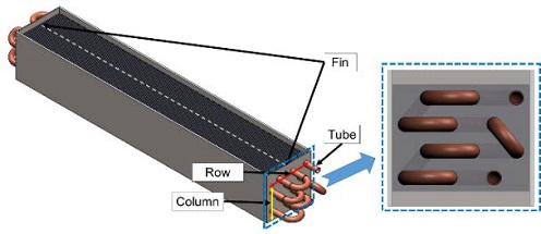
The heat exchanger used in this study is a fin-tube type heat exchanger, as shown in Figure 1. The heat exchanger is 65 mm wide, 51 mm high, and 390 mm long.
A flat fin that is 0.1 mm thick and made of aluminum is used. The fin spacing is 1.5 mm, and the tube is arranged in a staggered manner in four columns and three rows. The tube used is a single tube, not a multitube. This enables the cooling water to flow through a single tube and gradually gather heat from the air. The tube is made of copper, and its outer and inner diameters are 7 and 6 mm, respectively.
2.2 Heat dissipation design of water-cooled cabinet
Typical methods of heat dissipation in a cabinet include air cooling and water cooling. Air cooling is a method wherein the heat generated inside is released through the inflow of air from the outside. The minimum temperature of the parts inside the equipment becomes the ambient air temperature because the heat of the internal part is replaced by the external air. Consequently, the equipment’s internal parts operate in high ambient temperatures. In a water-cooled cabinet, heat dissipation occurs without outside air. As the air inside the equipment circulates, heat is transferred to the cooling water of the heat exchanger as well to the outside of the cabinet through the cooling water.
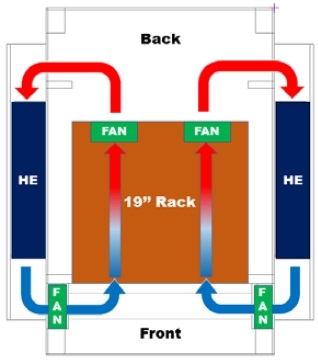
The water-cooled cabinets used in this study are equipped with cooling devices on both sides. The cooling system comprises a flow path through which internal air can flow and a heat exchanger that discharges heat generated by a 19-inch rack equipment into the cooling water. The heat inside the equipment is transferred to the heat exchanger by forming an internal flow using a fan. The flow path of the internal air as observed from the top of the cabinet is shown in Figure 2.
2.2 Process for predicting heat dissipation performance of water-cooled cabinet
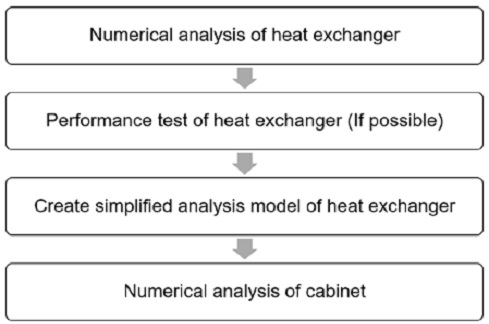
In this study, the process shown in Figure 3 was performed to predict the heat dissipation performance of the water-cooled cabinet.
The first step is creating an analytical model of the designed heat exchanger and performing a heat exchanger performance analysis under the expected air and cooling water.
The second step is manufacturing the heat exchanger after verifying that the performance of the heat exchanger above satisfies the target value, in addition to performing a heat exchanger performance test to predict the actual heat exchanger performance.
The third step is creating a simplified analytical model of the heat exchanger. When a single heat exchanger is analyzed, fluid flow analysis is performed using many grids by implementing the complex fins and tubes of the heat exchanger. When this method is used for fluid flow analysis, accurate analysis results can be obtained but the calculation is time-consuming. When the heat dissipation is calculated at the cabinet level, if all the heat exchangers are implemented to perform the calculation, then more computational resources will be used than necessary. To reduce computing resources, a simplified heat exchanger analysis model must be applied.
The fourth step involves applying a simplified heat exchanger analysis model to create an analytical cabinet model.
The fifth step is to perform thermal analysis at the cabinet level under the conditions in which the equipment is expected to operate.
3. Prediction of heat exchange performance at the single heat exchanger level
3.1 Theory
The effectiveness of the heat exchanger refers to the ratio of the maximum possible heat transfer rate to the actual heat transfer rate, as shown in Equation (1).
Here, ε is the effectiveness, q is the actual heat transfer rate, qmax is the maximum possible heat transfer rate, Ch is the thermal capacity of a hot fluid, Cc is the thermal capacity of a cold fluid, and Cmin denotes the smaller thermal capacity between the two fluids.
| (1) |
The heat transfer rate can be defined as shown in Equation (2) when the effectiveness and inlet temperature of both fluids are provided.
| (2) |
Both experimental and analytical methods can be used to verify the performances of heat exchangers. The experimental method is used to verify the performance of the heat exchanger by measuring the temperature, humidity, and pressure of two fluids through a calorimeter installed inside a temperature and humidity chamber.
When an analytical method is applied to a complex heat exchanger, the flow problem can be solved and verified directly via computational fluid dynamics (CFD). For simple heat exchangers, the effectiveness–NTU method or log mean temperature difference (LMTD) method is used [7].
LMTD is a method for determining the heat transfer area based on the mass flow rate as well as the inlet and outlet temperatures of two fluids when the type of heat exchanger is defined. The heat transfer rate of the heat exchanger can be defined as shown in Equation (3). Here, U is the coefficient of heat transmission, A is the heat transfer area, and ΔTm is the mean temperature difference.
| (3) |
The mean temperature difference depends on the location of the heat exchanger; therefore, the appropriate form of the mean temperature difference should be defined, e.g., that as shown in Equation (4). Here, ΔTlm is the LMTD, and F is the correction factor.
| (4) |
In parallel flow heat exchangers, the temperature difference between two ends can be defined as shown in Equation (5). Here, h represents the hot fluid, c the cold fluid, i the entrance, and o the exit.
| (5) |
In a counter flow heat exchanger, the temperature difference between two ends can be defined as shown in Equation (6).
| (6) |
The correction factor depends on the type of heat exchanger and the temperature of the inlet and exit of the two fluids in which heat transfer occurs. In general, the correction factor has a value smaller than 1. The value is approximately 1 if the heat transfer is concentrated, e.g., in a high-density heat exchanger, or if parallel flow or counter flow occurs in most areas when heat transfer occurs between the two media.
The effectiveness–NTU method yields the effectiveness as function of the NTU and heat capacity ratio, Cr.
| (7) |
In the effectiveness–NTU method, the parallel flow heat exchanger satisfies Equation (8).
| (8) |
The counter flow heat exchanger satisfies Equation (9).
| (9) |
If both fluids are non-mixed, then the cross flow heat exchanger satisfies Equation (10).
| (10) |
3.2 Flow type of heat exchanger
The flow type of a fin-tube heat exchanger with a single tube can be assumed to be either a macroscopic or microscopic flow.
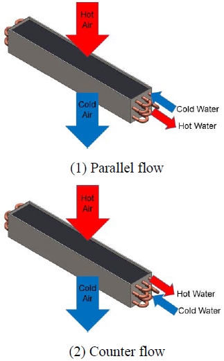
The macroscopic flow type can be divided into the parallel and counter flows from the viewpoint of temperature difference. If hot air encounters low-temperature cooling water and begins transferring heat with a large temperature difference, then a parallel flow is assumed. If hot air encounters high-temperature cooling water and begins transferring heat with relatively small temperature differences, then a counter flow is assumed. Each flow type is shown in Figure 4.
The microscopic flow type can be assumed to be a cross flow. This is because the fins and tubes are arranged orthogonally.
3.3 Operating conditions of heat exchanger
The expected operating conditions of the heat exchanger when it is operated are an air temperature of 50 °C and flow rate of 1.5 CMM (m3/min). The temperature of the cooling water that can be supplied to the heat exchanger is 10 °C, and the flow rate is 50 LPH (L/h).
In addition, six operating conditions were set (as shown in Table 1) to verify the performance based on changes in the flow rate and flow type of the cooling water. The flow rate of the cooling water was changed to 50, 80, and 125 LPH, and the flow type was either parallel or counter flow.
3.4 Prediction of heat exchanger effectiveness using fluid flow analysis
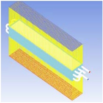
A fluid flow analysis of the heat exchanger was performed to predict the performance based on the operating conditions. The program used was FLUENT 18.2. The outlet temperature of the air and cooling water can be determined using fluid flow analysis. Subsequently, they can be used to calculate the effectiveness of the heat exchanger. Modeling all parts of the heat exchanger will result in an excessive computing burden owing to the thickness of the thin fins and the narrow fin spacing. Additionally, the quality of the grid will deteriorate. Hence, unnecessary parts were removed for fluid flow analysis, and the fins and tubes were simplified. The simplified analytical model was constructed as shown in Figure 5.
Generating a grid between the fins produced a relatively small grid, thereby reducing the quality of the grid in the border area of the fin. To solve this problem, a polyhedral grid was used. In addition, a boundary layer grid was created to calculate the flow between the fins. The total number of grids used was 30.3 million.
The turbulence model used was the realizable k–ɛ model, and the wall function used was the standard wall function. Mass flow inlet conditions were used for the air inlet and cooling water inlet boundary conditions, whereas pressure outlet conditions were used as the exit boundary conditions. The wall condition was used for the boundary condition of the fin and tube, and the shell conduction condition was used for the conductivity condition. Wall and insulation conditions were used as the boundary condition of the heat exchanger guide. Symmetry conditions were used on the side of the air area.
3.5 Results of fluid flow analysis
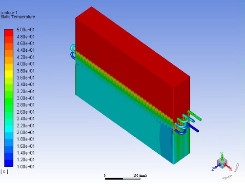
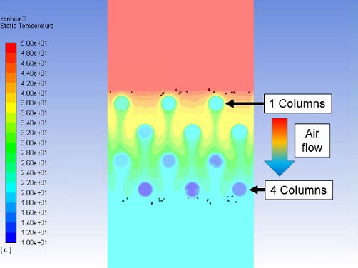
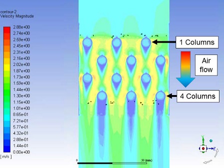
The fluid flow analysis results of the heat exchanger are shown in Figure 6. The outlet temperatures of the air and cooling water were derived from the fluid flow analysis results. Based on the temperature distribution between the fins, as shown in Figure 7, the temperature of the air decreased gradually and evenly while it passed through the heat exchanger. Figure 8 presents the velocity distribution between the fins of the heat exchanger.
Table 2 presents the effectiveness of the heat exchanger obtained using Equation (1). As the flow rate of the cooling water increases, the effectiveness of the heat exchanger increases. In addition, the effectiveness of the counter flow is higher than that of parallel flow at the same cooling water flow rate.
The counter flow is more efficient than the parallel flow because the mean temperature difference of the heat exchanger varies based on the flow type. To obtain the mean temperature difference of the fin-tube heat exchanger, the log mean temperature difference and the correction factor must be obtained. Assuming that the fin-tube heat exchanger used in this study has a constant parallel or counter flow in most areas, the correction factor can be assumed to be 1. If the mean temperature difference is obtained using Equation (4), then the value is as shown in Table 3. At the same flow rate, the mean temperature difference of the counter flow is greater than that of the parallel flow. Therefore, if the cooling water is supplied in the counter flow, the effectiveness of heat exchanger is increased. When a water-cooled cabinet is designed, it should be designed to provide cooling water to the counter flow.
Table 4 shows the effectiveness obtained from CFD simulations compared with those obtained using the effectiveness– NTU method.
In Table 4, the effectiveness was assumed to be that of the macroscopic flow type (parallel and counter flow) rather than that of the microscopic flow type (cross flow) for the CFD method. The flow type of the fin-tube heat exchanger with a single tube was assumed to be macroscopic when using the effectiveness–NTU method.
3.6 Heat exchanger performance test
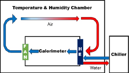
The heat exchanger was tested to verify its performance in an actual environment; subsequently, the results were compared with the results of fluid flow analysis. The heat exchanger performance test required a temperature and humidity chamber, calorimeter, and chiller. The test configuration is shown in Figure 9.
A temperature and humidity chamber is a device that maintains a constant temperature and humidity of the air entering the heat exchanger. A calorimeter is a device that supplies a constant air flow rate to the heat exchanger using a fan and measures the temperature and pressure of the air that passes through the heat exchanger. In this study, a heat exchanger was installed at the entrance of the calorimeter; subsequently, the temperature and flow rate of the air and cooling water were measured. The effectiveness of the heat exchanger was obtained using the temperature and flow rate of the air and cooling water measured from the test.
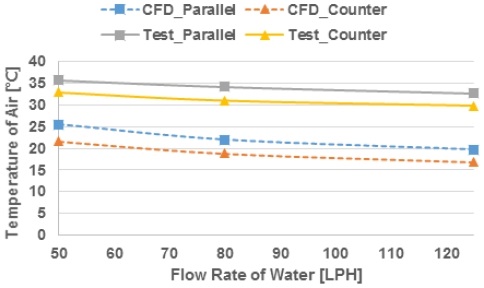
3.7 Results of heat exchanger performance test
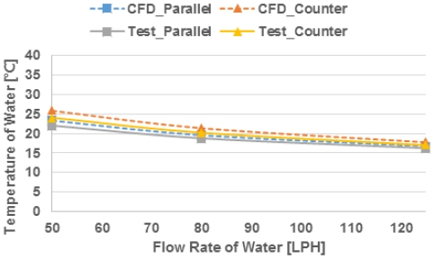
The outlet temperatures of the air and cooling water measured from the heat exchanger performance test are shown in Table 5, and the temperature under each operating condition is shown in Figure 10–11 based on the change in the flow rate of the cooling water. The outlet temperature of the air measured from the heat exchanger performance test was higher than the analysis result. This is due to the poor insulation and sealing of the calorimeter during the test. However, the measured temperature of the cooling water with less impact from the external environment was similar to the analytical results. The effectiveness obtained from the heat exchanger performance test was calculated based on the heat transfer rate of the cooling water.
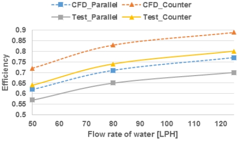
A comparison of the efficiencies obtained from the fluid flow analysis and heat exchanger performance test is shown in Table 6, and Figure 12 shows the effectiveness based on the flow type of the cooling water.
The effectiveness measured from the test was lower than that from the fluid flow analysis. Because the fluid flow analysis was performed while assuming dry air, the effect due to the phase change of water vapor was disregarded. In the actual test, the water vapor phase changed, and condensation occurred on the fins and tubes. This condensation water interfered with the heat transfer of the heat exchanger and reduced the effectiveness of the heat exchanger. The test results for effectiveness of the parallel flow measured 8.1% to 9.15% higher, whereas those of the counter flow measured 10.1% to 11.1% higher compared with the CFD results.
4. Prediction of heat dissipation performance at cabinet level
4.1 Theory
To verify the operating environment of the internal equipment of the cabinet, a thermal analysis of the cabinet was performed.
The analytical model of the heat exchanger was implemented using a heat exchanger analysis model provided by ICEPAK. The model required the pressure drop, cooling water average temperature, and heat transfer coefficient as input values.
The test results (Case 50-C) of the heat exchanger performance test were used to obtain the pressure drop, average temperature of the cooling water, and heat transfer coefficient (h). Furthermore, the amount of pressure drop corresponding to the velocity of air passing through the heat exchanger was used. The average temperature of the cooling water was obtained using the measured cooling water temperature, and the heat transfer coefficient was obtained using Equation (11) below, where is the mass flow rate of air, Cp the specific heat of air, Acs the cross-sectional area of the heat exchanger, Tair,u the temperature of the air upstream of the heat exchanger, Tair,d the air temperature downstream of the heat exchanger, and Text the average temperature of the cooling water.
| (11) |
The average temperature of the cooling water was 15.59 °C, and the heat transfer coefficient was 2537.47 W/Km2.
4.2 Method for thermal analysis of water-cooled cabinet
The water-cooled cabinet has a closed structure and discharges the internal heat through a heat exchanger. The water-cooled cabinet measures 820 mm wide, 1800 mm high, and 1000 mm deep. The operation condition of the internal equipment was determined by balancing the heat transfers from the outside, internal equipment, and cooling water of the heat exchanger. No flow occurred outside the water-cooled cabinet except for heat transfer by natural convection.
A value representative of the operating environment of the internal equipment is the air temperature introduced into the rack equipment. To predict this, a thermal analysis of the cabinet was performed. The program used was ICEPAK 17.2.
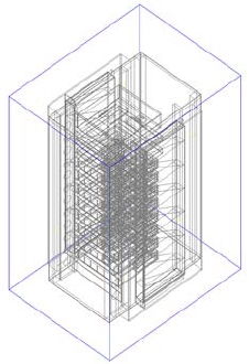
Modeling all parts of the cabinet would result in excessive computing burden and a poor grid quality. Hence, the parts that were unnecessary for thermal analysis were deleted and simplified. The total number of grids used was 700,000. The analysis model is shown in Figure 13.
The zero equation model was used in the turbulence model, and the radiation effect was minimal within operating temperature; therefore, radiation was not applied. The water-cooled cabinet was modeled using cabinet models, and the opening conditions were used as the boundary conditions. For the fan generating an internal flow, the pressure drop used was based on the speed.
To predict the operating environment of the internal rack equipment, thermal analyses were performed in both general and severe operating conditions. The ambient temperature was set to 25 °C and 50 °C for the general and severe operation conditions, respectively.
4.3 Results of thermal analysis and reviews
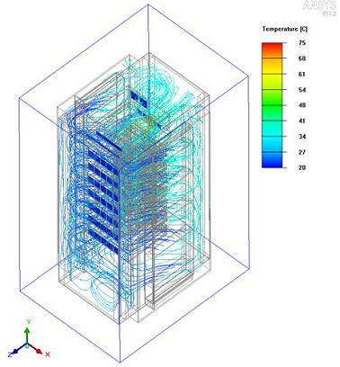
Based on the streamline of the internal flow, it was discovered that hot air was evenly distributed to both side and passed through the heat exchanger. The air passing through the heat exchanger was cooled by the cooling water. An internal flow was formed based on the heat dissipation design, and the heat inside the cabinet was discharged smoothly through the heat exchanger. A streamline representing the internal flow is as shown in Figure 14.
The average air temperature introduced into the internal rack equipment can determine the heat dissipation stability of the water-cooled cabinet. The temperature of the air entering the rack equipment is shown in Table 7. Temperature distribution ranges of 24.1 °C–24.7 °C and 25.7 °C–26.8 °C were formed in the general and severe operation conditions, respectively. It was discovered that the water-cooled cabinet guaranteed the heat dissipation stability. Under both conditions, the rack equipment can be operated in an environment similar to a room-temperature environment.
The heat transfer in a water-cooled cabinet comprises three paths, as shown in Table 8. The first is the amount of heat dissipation generated by the rack equipment inside the cabinet. The second is the amount of heat absorbed by the heat exchanger. The third is the heat transfer between the ambient air and the cabinet. Heat transfer between the ambient air and the cabinet is caused by a relative temperature difference between the ambient air and the air inside the cabinet. In severe operating conditions, heat enters from the outside to the inside, and vice versa under general operating conditions. When the difference in the ambient temperature was 25 °C, the heat transfer difference was 452.9 W. The amount of heat transfer was 12.2% of the heat generated from the electronic components inside the rack equipment, i.e., a relatively small amount. Consequently, the difference in the air temperature introduced into the internal rack equipment was small compared with the difference in the ambient temperature.
In an air-cooled cabinet, when the outside air temperature increases, the temperature of the electronic components inside the rack increases proportionally. However, water-cooled cabinets are less affected by the ambient temperature. This feature guarantees heat dissipation stability when the operating rack equipment is vulnerable to high ambient temperatures.
5. Conclusion
In this study, the performance of a heat exchanger was verified using analytical and experimental methods, and a water-cooled cabinet was designed.
Analytical and experimental methods were used to determine the performance of the four-stage three-row fin-tube heat exchangers used in water-cooled cabinets. In this process, the characteristics of the fin-tube heat exchanger connected by a single tube based on the flow type were identified. In addition, the thermal analysis of water-cooled cabinets using a fin-tube heat exchanger was performed. The thermal analysis results at the cabinet level confirmed the heat dissipation stability of the internal rack equipment based on the ambient temperature.
① A numerical analysis method was used to construct a process for predicting the heat dissipation performance from a single heat exchanger to the cabinet level.
② The flow type of a fin-tube heat exchanger with a single tube can be assumed to be macroscopic (parallel and counter flows) when using the effectiveness–NTU method.
③ The performance of the heat exchanger was predicted via CFD simulations; it was calculated that the parallel flow was 8.1% to 9.15% higher and the counter flow was 10.1% to 11.1% higher than the experimental results.
④ The effectiveness of the heat exchanger depended on flow type of the heat exchanger. The counter flow was more efficient than the parallel flow.
⑤ Thermal analysis was performed at the cabinet level based on the operating conditions of the water-cooled cabinet. Temperature distributions of 24.1–24.7 °C and 25.7–26.8 °C under general and severe operating conditions, respectively, were indicated.
The water-cooled cabinet was less affected by the change in the ambient temperature and guaranteed the heat dissipation stability of the internal rack equipment under a high outside ambient temperature.
Author Contributions
Conceptualization, S. J. Ha, J. H. Park, M. J. Jeong, and D. S. Lee; Methodology, S. J. Ha, J. H. Park, and K. S. Jeon; Software, S. J. Ha and J. H. Park; Validation, K. S. Jeon, M. J. Jeong, and D. S. Lee; Formal Analysis, S. J. Ha and Y. M. Lee; Resources, K. S. Jeon; Data curation S. J. Ha; Writing-Original Draft Preparation, S. J. Ha and J. H. Park; Writing-Review & Editing, S. J. Ha; Visualization, S. J. Ha.
References
-
Z. Liu and J. -K. Yoon, “A study on heat transfer and pressure drop characteristics of plain fin-tube heat exchanger using CFD analysis,” The Korean Society of Marine Engineering, vol. 38, no. 6, pp. 615-624, 2014 (in Korean).
[https://doi.org/10.5916/jkosme.2014.38.6.615]

-
H. -J. Kim, H. -S. Lee, J. -I. Yoon, C. -H. Son, and Y. -K. Jung, “A numerical study on heat transfer and pressure drop of plate heat exchanger using at seawater air conditioning with the variation of channel spaces,” The Korean Society of Marine Engineering, vol. 38, no. 6, pp. 704-709, 2014 (in Korean).
[https://doi.org/10.5916/jkosme.2014.38.6.704]

-
J. -H. Yoo and J. -K. Yoon, “Numerical analysis for heat transfer characteristics of elliptic fin-tube heat exchanger with various shapes,” Transactions of the Korean Society of Mechanical Engineers, vol. 37, no. 4, pp. 367-375, 2013 (in Korean).
[https://doi.org/10.3795/KSME-B.2013.37.4.367]

- B. -J. Kim, J. -H. Park, and Y. -E. Jin, “A study on the cooling performance of electronic cabinet equipment using water cooling system,” 2012 Fall Conference of the Korean Society of Mechanical Engineers, pp. 2765-2769, 2012 (in Korean).
- H. Choi, J. Lee, and B. Kim, “A study for cooling performance of electronic cabinet of shipboard,” Proceedings of the KFMA Annual Meeting, pp. 191-192, 2013 (in Korean).
- S. G. Na, J. Y. Choi, T. W. Hwang, “Numerical study of electronic cabinet equipped with unmixed cross-flow heat exchanger for thermal stability,” 2016 Fall Conference of Korean Society for Precisions Engineering, pp. 38-39, 2016 (in Korean).
- F. P. Incropera, Introduction to Heat Transfer, 5th ed., Hobokenm NJ : Wiley, 2007.
