Numerical analysis of pressure drop and temperature in a hairpin heat exchanger with different shell and tube bank arrangements
Copyright ⓒ The Korean Society of Marine Engineering
This is an Open Access article distributed under the terms of the Creative Commons Attribution Non-Commercial License (http://creativecommons.org/licenses/by-nc/3.0), which permits unrestricted non-commercial use, distribution, and reproduction in any medium, provided the original work is properly cited.
Abstract
In this numerical study, the hairpin type shell and tube heat exchanger is analyzed for heating the cryogenic liquefied natural gas (LNG). The cryogenic LNG is passed through the tube side and is heated by the hot water on the shell side of the hairpin heat exchanger. In order to increase the performance of the heat exchanger, maximum heat needs to be extracted from the hot water and transferred to the LNG stream. Thus, different arrangement of shell and tube sides of the hairpin heat exchanger are used to study the pressure drop in the hot water and to increase the temperature of the LNG. The effects of horizontal and vertical baffles orientation, staggered and aligned tube bank arrangements, baffles number (6, 8, 10 and 12), and baffles cut percentages were used to analyze the pressure drop and temperature difference in the exchanger. The results show that the pressure drop is decreased and the tube outlet temperature is increased in the heat exchanger for the percentage of baffle cut changes from 22.5% to 37.5%. Also, increasing the number of baffles increases both the temperature and pressure drop in the hairpin heat exchanger. Furthermore, comparing horizontal and vertical baffle orientation, pressure drop is always lower and LNG outlet temperature is always higher in the horizontal baffle orientation for both tube bank arrangement systems. However, in the horizontal baffle orientation the pressure drop for staggered tube bank arrangement is smaller than that of aligned tube bank arrangement, but the temperature of aligned tube bank is higher compared to the staggered tube bank arrangement.
Keywords:
Hairpin heat exchanger, Pressure drop, Temperature, Baffles1. Introduction
Liquefied natural gas – the cleanest burning fossil fuel – is the product of raw natural gas. LNG fuel has many advantages over conventional fuel, such as higher thermal efficiency, non-toxicity, and non-corrosiveness. Hence, the demand for LNG has increased globally. However, most raw natural gas plants are in remote areas. Hence, it is difficult or impractical to transfer natural gas from the source to the users via pipelines. Therefore, natural gas is converted to a cryogenic state, where low temperature of approximately −162 °C shrinks the gas volume by 600 times. It is then transported to the desired destination. Once the LNG arrives at the desired destination, it is heated by a heat exchanger for usage in different applications, such as automobile engines, power generation [1], air separation [2], air conditioning system [3], and freeze desalination [4].
There are many types of heat exchangers currently used in the industry, such as hairpin heat exchanger, plate and frame heat exchanger, plate-fin heat exchanger, spiral heat exchanger, air coolers and condenser, direct contact and fired heaters, etc. [5]. The hairpin type shell and tube heat exchanger is used in this study. The hairpin heat exchanger is also called as the double pipe, multi-pipe, or G-fin heat exchanger. The hairpin heat exchanger is a double pass shell and tube heat exchanger that is folded in half, similar to a hairpin. It provides true counter fluid flow and is particularly suitable for high pressure and temperature analysis.
To obtain an effective design of the hairpin heat exchanger, the flow and heat transfer characteristics are crucial. Fettaka et al. studied the design of shell and tube heat exchangers using multi-objective optimization with Non-dominated Sorting Genetic Algorithm (NSGA-II) algorithm to provide Pareto-optimal solutions with various decision variables. The results showed that a low value of heat transfer area and pumping power was achieved and the three factors, i.e., tube length, diameter, and thickness, had a minor effect on the optimal cost design [6]. Kumaresan et al. studied the baffle cut impact on a shell-side heat exchanger with inclined baffles. The results showed that the heat transfer using an inclined baffle heat exchanger was maximum compared to a segmental baffle heat exchanger. Additionally, for a configuration of 35° baffle inclination angle and baffle cut of 30% of the inner shell diameter provided higher heat transfer rate with minimum pressure drop [7]. Ozden and Tari studied the shell-side design of a small shell and tube heat exchanger numerically. They conducted Computational Fluid Dynamics (CFD) simulations for a single shell and single tube pass heat exchanger with different number of baffles and turbulent flows, and they compared the results with that of the Bell-Delaware method. The results showed that the k–ε realizable turbulence model was the best simulation approach [8]. Abdelkader and Zubair studied the performance of the shell and tube heat exchanger based on the baffle number using the Kern, Bell-Delaware, and flow-stream analysis methods. The results showed that as the number of baffles increased, the heat transfer coefficient and pressure drop increased on the shell-side, and for a large number of baffles, the square layout had the highest heat transfer coefficient [9]. H Ay et al. experimentally studied the local heat transfer measurements of the plate finned-tube heat exchangers with inline and staggered tube arrangements by infrared thermography using the control volume based finite difference formula. The results showed that there was 14–32% increase in the averaged heat transfer coefficient of staggered configuration compared to the inline configuration [10]. Yadav experimentally studied the heat transfer and pressure drop characteristics inside a double pipe U-Bend heat exchanger with and without half-length twisted-tape turbulators. The results showed that using the half-length twisted-tube turbulator achieved a 40 % increase in the heat transfer coefficient compared to the plain exchanger. The heat transfer performance of the twisted tape turbulator was better than that of the plain exchanger in terms of equal mass flow rate, and the heat transfer performance of the plain exchanger was better than that of the twisted tube turbulator in terms of unit pressure drop. Additionally, the results showed that the thermal performance was 1.3 – 1.5 times better for the plain exchanger than the twisted tube turbulator [11]. Mohammadi et al. studied the effects of horizontal and vertical baffle orientations and viscosity on heat transfer and pressure drop in a shell and tube heat exchanger with leakage flows numerically.
The results showed that the vertical baffle orientation is more advantageous than the horizontal baffle orientation for all the shell-side fluids [12]. Dey et al. numerically studied the effects of various baffle orientations and sizes on the shell-side pressure drop in a liquefied natural gas vaporizer. The results showed that the horizontal baffle orientation and the 50% baffle cut had a low pressure drop compared to other configurations. Moreover, the pressure drop dependency on the Reynolds number decreased for all baffle orientations for baffle cuts from 30% to 50% [13].
Although significant amount of work has been conducted for analyzing the pressure drop and heat transfer characteristics in the heat exchanger, studies on the hairpin type shell and tube heat exchanger are scarce.
In this study, the pressure drop and temperature difference in the hairpin heat exchanger are numerically investigated for different baffle cuts (22.5%, 30%, and 37.5% of shell inner diameter), baffle numbers (6, 8, 10, and 12), baffle orientations (horizontal and vertical), and tube bank arrangements (staggered and aligned).
2. Numerical Analysis
2. 1 Geometry Modeling and Grid Generation
Figure 1 (a) shows the schematic of the hairpin heat exchanger. It consists of two domains, i.e., shell domain and tube domain. The shell domain consists of shell cover, inlet port, outlet port, and baffles. The tube domain consists of tubes, inlet header, and outlet header. The shell cover covers the total shell-side fluid, and the baffles are welded on the inside of the shell cover to enhance the mixing and turbulence of the shell-side fluid stream. The baffles are used to support the structural rigidity of the tube, prevent tube vibration and sagging, maintain tube spacing, and divert the flow across the tube bundle. There are several different designs for baffles, such as segmental, curve, and helical baffles. A segment, called the baffle cut, is cut away to allow the fluid to flow parallel to the tube axis as it flows from one baffle space to another. Due to manufacturing convenience, single segmental baffles are more commonly used compared to curved or helical baffles. Figure 1 (b) shows a schematic of the single segmental baffle with horizontal and vertical baffle cuts according to the shell inlet axis. In heat exchangers, tube banks are commonly employed design elements. Figure 1 (c) shows two types of tube bank arrangements, namely staggered and aligned tube bank arrangements. In the staggered configuration (horizontal direction), all tubes are parallel horizontally, whereas in the vertical direction the tubes are offset. In the aligned configuration, all the horizontal and vertical tubes are inline and in a square arrangement.
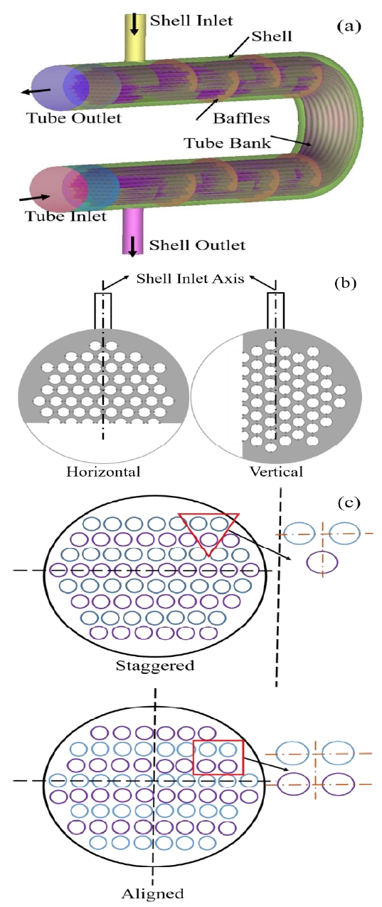
Schematic of the hair pin type shell and tube heat exchanger; (a) Geometric aspects of the hairpin heat exchanger, (b) Horizontal and vertical orientation of baffles, (c) Staggered and aligned tube bank arrangement
Table 1 shows the geometrical parameters of the hairpin heat exchanger used in this study. CFD modelling and meshing are performed by CATIA V5 and ICEM CFD, respectively. The shell and tube-side domain meshing are generated by the unstructured tetra-mixed robust (octree) volume mesh method, whereas the prism mesh is generated near the tube wall. At the domain interface, the prism meshes on the tube domain and tetrahedral meshes on the shell domain are connected by the general grid interface mesh connecting method. The shell-side hot water transfers heat through the interface material to the tube-side LNG fluid. Normally, aluminum is used as the tube material in the shell and tube heat exchanger. However, for the LNG heat exchanger, stainless steel is used for handling the cryogenic fluid because, at low temperatures, aluminum changes to its atomic bond and becomes a brittle material. Therefore, to maintain the hardness of the material stainless steel tubes are used in the LNG heat exchanger.
2. 2 Governing Equations
➢ Continuity Equation:
In fluid dynamics, the continuity equation is an expression of conservation of mass. For a steady and incompressible flow, the continuity equation is expressed by
| (1) |
➢ Momentum Equation:
The Navier-Stokes equations are the basic governing equations of fluid flow. They are obtained by applying Newton’s second law of motion to a fluid element. The Reynolds averaged Navier-Stokes (RANS) momentum equation is given b
| (2) |
➢ Thermal Energy Equation:
The thermal energy is responsible for the change in the temperature of the system, and it is given by
| (3) |
➢ 𝑘− 𝜀 standard model:
The 𝑘−𝜀 standard model of turbulence is based on k and ε, whose values come directly from the differential transport equations for turbulent kinetic energy and energy dissipation rate.
| (4) |
| (5) |
The effective viscosity is given as
| (6) |
The 𝑘−𝜀 model assumes that the turbulent viscosity is linked to the turbulent kinetic energy and energy dissipation rate by the relationship shown below:
| (7) |
𝑃𝑘 is the turbulence production, which is modelled by
| (8) |
The values of physical constants for k – ε are assigned as
∁𝜀1=1.44, ∁𝜀2=1.92, ∁𝜇=0.09, 𝜎𝑘=1.00, 𝜎𝜀=1.3
➢ Heat Transfer Prediction:
The exit temperatures are calculated by the ε-NTU method, as shown in [14]. The ε-NTU method formulas are defined as the rate of heat transfer in the shell-side fluid of the heat exchanger. It is given by
| (9) |
The rate of heat transfer in the tube-side fluid of the heat exchanger is given by
| (10) |
The average heat exchange rate is
| (11) |
The heat transfer area is expressed as
| (12) |
The heat exchanger effectiveness is given by
| (13) |
The number of transfer units is calculated by
| (14) |
The maximum possible heat transfer is expressed as
| (15) |
2. 3 Boundary Conditions
The fluid mass flow rate and temperature are used as the input parameters at the inlets of hot and cold fluids, respectively. The hot water is passed through the shell-side of the heat exchanger. The inlet mass flow rate of hot water is considered as 10–20 ton/hr. Based on the inlet mass flow rate of hot water, the Reynolds number is calculated. The Reynolds number is defined as
| (16) |
The inlet temperature is taken as 80 °C. The water density is 997 kg/m3, heat capacity is 4181.7 J/kg ℃, dynamic viscosityis 8.899×10⁻⁴ kg/ms, and thermal conductivity is0.6069 W/m℃. The cryogenic LNG is passed through the tube-side of the heat exchanger. The mass flow rate and temperature of the LNG are 2 ton/h and −145 ℃, respectively. The LNG density is 0.717 kg/m3, heat capacity is 2210 J/kg ℃,dynamic viscosity is 11.1×10⁻⁶kg/ms, and thermal conductivity is 343×10−4 W/m ℃. In both domains, the boundaryconditions for the outlet is defined as the pressure outlet, and the pressure value is assigned as zero Pascal to create a pressure variation for the flow to continue smoothly through the boundary. The momentum boundary condition of no slip and adiabatic heat transfer are set for all solid walls.
3. Results and Discussion
3. 1 Grid Independence Test
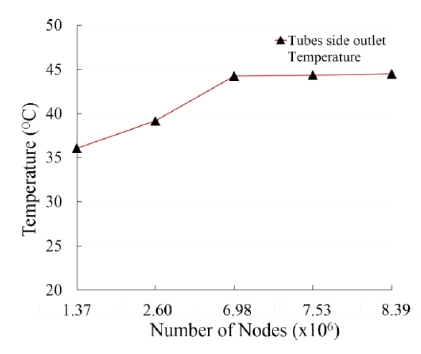
Figure 2 shows the number of nodes used to calculate the independence of grid size. From the figure, it can be observed that the tube-side outlet temperature increased gradually with an increase in the number of nodes from 1.37×10⁶ to 6.98×10⁶. Additionally, the tube-side outlet temperature was investigated for the node number 7.53×10⁶ and 8.39×10⁶. However, the tube-side outlet temperature remained unchanged because the grid became independent. The number of nodes chosen as the final mesh size for performing the simulation was 6.98×10⁶.
3. 2 Comparison of numerical results with the analytical method
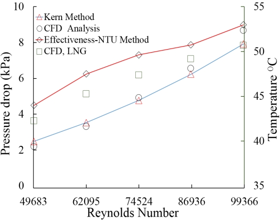
Figure 3 shows the pressure drop and temperature difference against Reynolds number and compares the numerical results with the Kern method [15] and ε-NTU method for analyzing the shell-side pressure drop and tube-side temperature difference, respectively. The Kern method is a well-known and widely accepted method used to analyze the pressure drop in a system. To verify the pressure drop of the heat exchanger, we compared the pressure drop of the heat exchanger with that of the Kern method. The pressure drop results showed an average difference of 5% or more. From the results, it can be concluded that the pressure drop of the heat exchanger was well within the agreeable limits. The ε-NTU method is used to analyze the outlet temperature of the system only when the inlet temperature is known. The CFD results showed an average difference of approximately 5% for outlet temperature compared to the ε-NTU method. This shows that the outlet temperature of the system was well within the agreeable limits. From the above comparisons, it can be concluded that the numerical analysis performed in this study was reliable.
3. 3 Effects of Baffle Cut
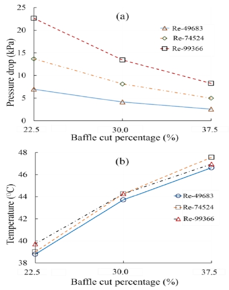
Figure 4 shows the effect of baffle cuts on the pressure drop and temperature at the shell and tube-side of the heat exchanger, respectively. It was found that the pressure drop at the shell-side of the heat exchanger decreased as the baffle cut percentage increased, as shown in Figure 4 (a).
On the other hand, the tube-side temperature of the heat exchanger increased as the baffle cut percentage increased, as shown in Figure 4 (b). The results showed that the baffle cut of 37.5% had the lowest pressure drop and highest outlet temperature because additional shell-side fluid could flow across the bigger baffle window. However, the temperature decreased for the baffle cut percentage between 30% and 37.5% due to the increased dead zone owing to the high Reynolds number.
3. 4 Effect of Number of Baffles
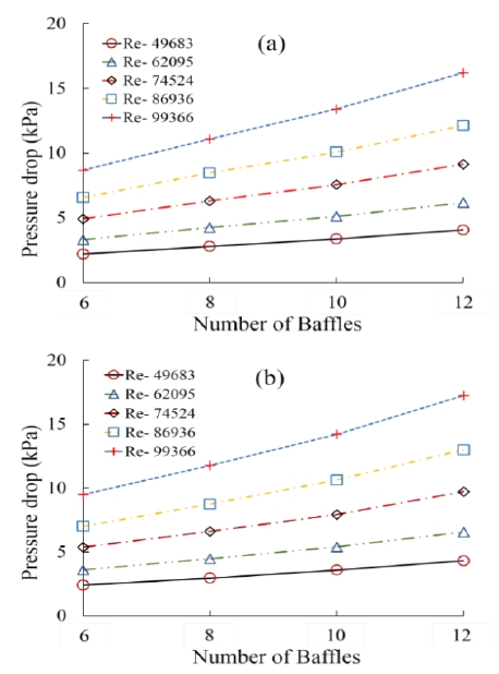
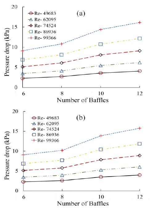
Figures 5 and 6 show the pressure drop caused by vertical and horizontal baffles on the shell-side for the staggered and aligned tube bank arrangements, respectively. From these figures, it can be observed that the pressure drop increased linearly as the number of baffles and Reynolds number increased. The pressure drop caused by 12 baffles was significantly higher than that caused by other baffle numbers. This occurs due to the resistance offered by the increasing number of baffles, which led to the pressure drop at the shell-side of the heat exchanger.
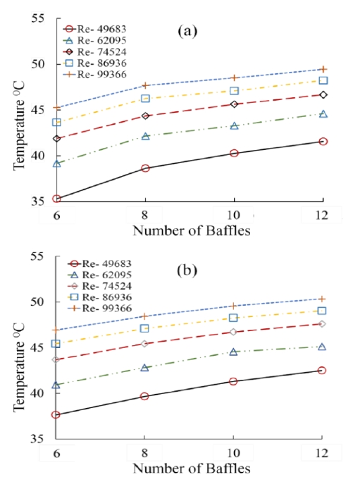
Figure 7 (a) and (b) shows the temperature difference at the tube-side of the heat exchanger for vertical baffles with staggered and aligned tube bank arrangements, respectively. The tube-side temperature depends on the Reynolds number and baffle number because when the number of baffles increased, the spacing between the baffles decreased. Hence, the contact time increased between the shell and tube-side fluids, which led to an increase in the temperature of the heat exchanger.
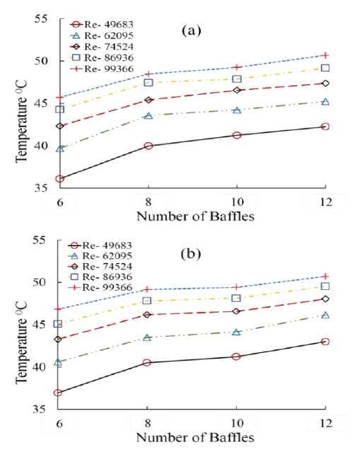
Figure 8 (a) and (b) shows the temperature difference at the tube-side of the heat exchanger for horizontal baffles with staggered and aligned tube bank arrangements, respectively. From the figure, it can be observed that the tube-side outlet temperature changed in a similar manner as that of the vertical baffle orientation, as shown in Figure 7.
3. 5 Effect of Baffle Orientation
Figure 9 (a) and (b) shows the results of the shell-side pressure drop for vertical and horizontal baffles with staggered and aligned tube bank arrangements, respectively. For both the baffle orientations, 8 and 12 baffles were used to compare the results. The shell-side pressure drop for the staggered tube bank arrangement with 8 baffles horizontally oriented was slightly smaller compared to the shell-side pressure drop for the vertical baffle orientation, as shown in Figure 9 (a). However, the results of shell-side pressure drop for the horizontal and vertical baffle orientations with staggered tube bank arrangements and 12 baffles showed no variations.
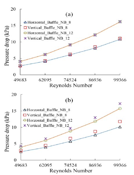
Shell-side pressure drop for horizontal and vertical baffles; (a) Staggered tube bank and (b) Aligned tube bank
From Figure 9 (b), it can be observed that for the case of 8 horizontal and vertical baffles with a low Reynolds number, the difference in the shell side pressure drop between the two orientations was 0.25 kPa, and for high Reynolds number, the difference in the shell side pressure drop between the two orientations was 1.5 kPa.
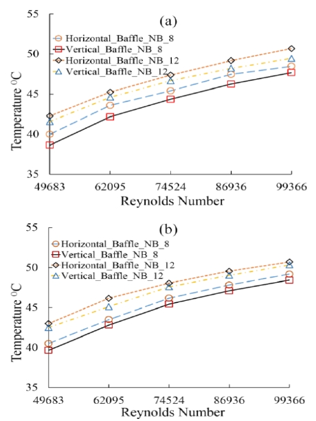
Similar results were observed for 12 baffles. Figure 10 (a) and (b) shows the tube-side temperature for the horizontal and vertical baffles for the staggered and aligned tube bank arrangements, respectively. From these figures, it can be observed that the temperature was higher for the horizontal baffles compared to the vertical baffles for both the cases of 8 and 12 baffles.
3. 6 Effect of Tube Bank Arrangement
Figure 11 (a) and (b) show the shell-side pressure drop and tube-side temperature difference for the horizontal baffle orientation for both staggered and aligned tube bank arrangements, respectively.
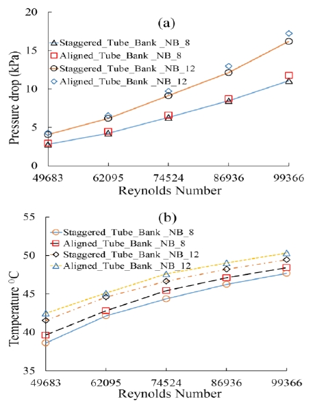
(a) Comparison of shell-side pressure drop and (b) tube-side temperatures for staggered and aligned tube bank arrangements in horizontal baffle orientation
The results showed that for baffle numbers 8 and 12, the aligned tube bank arrangement had a higher pressure drop compared to the staggered tube bank arrangement, as shown in Figure 11 (a). However, the aligned tube bank arrangement had a higher temperature compared to the staggered tube bank arrangement, as shown in Figure 11 (b). This was because the heated elements in the aligned tube bank were exposed in the mainstream unlike that in the staggered tube bank arrangement.
4. Conclusion
A numerical simulation is performed to investigate the pressure drop and temperature difference of the hairpin heat exchanger using baffle cut, baffle number, baffle orientation, and tube bank arrangements for various Reynolds numbers. The following conclusions are derived from this numerical study:
- (I) Three different baffle cuts (22.5%, 30%, and 37.5%) and Reynolds numbers (49683, 74524, and 99366) are analyzed. The maximum pressure drop and temperature difference for the three baffle cuts were 14 kPa, 8 kPa, and 3 kPa, and 7.8 ℃, 5 ℃, and 5.6 ℃, respectively.
- (II) The temperature variation on the tube outlet of the hairpin heat exchanger is analyzed for different number of baffles, i.e., 6, 8, 10, and 12. The results showed that the highesttemperature was achieved when 12 baffles were used because the heat transfer time increased between shell-side water and tube-side fluid due to the increased number of baffles.
- (III) In the horizontal and vertical baffle orientations for the two types of tube bank arrangement, the pressure drop and temperature difference in the vertical baffle orientation was always higher and lower, respectively, than the horizontal baffle orientation because the shell-side fluid flow was less twisted and more regular in the horizontal baffle orientation compared to the vertical baffle orientation.
- (IV) A comparative study of tube banks for the horizontal baffle orientation showed that the pressure drop for staggered tube bank arrangement was smaller than that of the aligned tube bank arrangement. However, the temperature of that aligned tube bank arrangement was approximately 4% to 5% higher for baffle numbers 8 and 12 compared to that of the staggered tube bank arrangement.
Glossary
| Nomenclature | |
|---|---|
| A : | heat transfer area, m2 |
| U : | velocity, m/s |
| D : | tube outer diameter, m |
| S : | pitch, m |
| K : | thermal conductivity, W/(m C) |
| Q : | heat exchange rate, W |
| l : | tube length, m |
| N : | number of tubes |
| NTU : | number of transfer unit |
| T : | temperature, C |
| P : | pressure, Pa |
| Cp : | specific heat, J/(kg C) |
| ΔT : | temperature difference, C |
| U : | overall heat transfer coefficient, W/(m C) |
| Greek letters: | |
|---|---|
| ε : | effectiveness |
| ρ : | density, kg/m3 |
| : | mass flow rate, kg/m3 |
| μ : | dynamic viscosity, kg/s. |
| μt : | turbulence viscosity, kg/s |
| ∁𝜀1 : | k-ε turbulence model constant, 1 |
| ∁𝜀2 : | k-ε turbulence model constant, 2 |
| ∁𝜇,𝜎𝑘,𝜎𝜀 : | k-ε turbulence model constant |
| Subscripts: | |
|---|---|
| i, j, k : | tensor |
| Avrg : | average value |
| max : | maximum |
| min : | minimum |
| s : | shell |
| t : | tube |
| T : | transverse |
| L : | longitudinal |
| D : | diagonal |
| eff : | effective |
Acknowledgments
This study is carried out with the general support of the Ministry of Industry for Economic Cooperation (problem number A012800345) and the Human Resources Program in Energy Technology of the Korea Institute of Energy Technology Evaluation and Planning (KETEP) granted financial resource from the Ministry of Trade, Industry and Energy, Republic of Korea (No. 20184010201700).
Author Contributions
Conceptualization, M. K. Dey and Y. W. Lee; Methodology, M. K. Dey and Y. W. Lee; Software, M. K. Dey; Formal Analysis, M. K. Dey and N. Parthasarathy; Investigation, M. K. Dey; Resources, M. K. Dey and Y. W. Lee; Data curation, M. K. Dey and N. Parthasarathy; Writing-Original Draft Preparation, M. K. Dey; Writing-Review & Editing, N. Parthasarathy and Y. W. Lee; Visualization, M. K. Dey; Supervision, Y. W. Lee; Project Administration, Y. W. Lee; Funding Acquisition, Y. W. Lee.
References
-
C. Dispenza, G. Dispenza, V. L. Rocca, and G. Panno, “Exergy recovery during LNG regasification: Electric energy production - part one & two,” Applied Thermal Engineering. vol. 29, no. 2-3, pp. 380-399, 2009.
[https://doi.org/10.1016/j.applthermaleng.2008.03.036]

-
M. Mehrpooya, M. M. M. Sharifzadeh, and M. A. Rosen, “Optimum design and exergy analysis of a novel cryogenic air separation process with LNG (liquefied natural gas) cold energy utilization,” Energy, vol. 90, part 2, pp. 2047-2069, 2015.
[https://doi.org/10.1016/j.energy.2015.07.101]

-
V. L. Rocca, “Cold recovery during regasification of LNG part one: Cold utilization far from the regasification facility,” Energy, vol. 35, no. 5, pp. 2049-2058, 2010.
[https://doi.org/10.1016/j.energy.2010.01.022]

-
W. Cao, C. Beggs, and I. M. Mujtaba, “Theoretical approach of freeze seawater desalination on flake ice maker utilizing LNG cold energy,” Desalination, vol. 355, pp. 22-32, 2015.
[https://doi.org/10.1016/j.desal.2014.09.034]

-
R. K. Shah and D. P. Sekulic, Fundamentals of Heat Exchanger Design, John Wiley & Sons, Inc., 2003.
[https://doi.org/10.1002/9780470172605]

-
S. Fettaka, J. Thibault, and Y. Gupta, “Design of shell-and-tube heat exchangers using multiobjective optimization,” International Journal of Heat and Mass Transfer, vol. 60, pp. 343-354, 2013.
[https://doi.org/10.1016/j.ijheatmasstransfer.2012.12.047]

-
G. Kumaresan, R. Santosh, P. Duraisamy, R. Venkatesan, and N. S. Kumar, “Numerical analysis of baffle cut on shell side heat exchanger performance with inclined baffles,” Heat Transfer Engineering, vol. 39, no. 13-14, pp. 1156-1165, 2018.
[https://doi.org/10.1080/01457632.2017.1363624]

-
E. Ozden and I. Tari, “Shell side CFD analysis of a small shell-and-tube heat exchanger,” Energy Conservation and Management, vol. 51, no. 5, pp. 1004-1014, 2010.
[https://doi.org/10.1016/j.enconman.2009.12.003]

-
B. A. Abdelkader and S. M. Zubair, “The effect of a number of baffles on the performance of shell-and-tube heat exchanger,” Heat Transfer Engineering, vol. 40, no. 1-2, pp. 39-52, 2019.
[https://doi.org/10.1080/01457632.2017.1404806]

-
H. Ay, J. Y. Jang, and J. N. Yeh, “Local heat transfer measurements of plate finned-tube heat exchangers by infrared thermography,” International Journal of Heat and Mass Transfer, vol. 45, no. 20, pp. 4069-4078, 2002.
[https://doi.org/10.1016/S0017-9310(02)00132-1]

- A. S. Yadav, “Effect of half length twisted-tape turbulators on heat transfer and pressure drop characteristic inside a double pipe U-bend heat exchanger,” Jordan Journal of Mechanical and Industrial Engineering, vol. 3, no. 1, pp. 17-22, 2009.
-
K. Mohammadi, W. Heidemann, and H. Müller-Steinhagen, “Numerical investigation of the effect of baffle orientation on heat transfer and pressure drop in a shell and tube heat exchanger with leakage flows,” Heat Transfer Engineering, vol. 30, no. 14, pp. 1123-1135, 2010.
[https://doi.org/10.1080/01457630902972694]

-
M. K. Dey, H. J. Kim, Y. H. Choi, S. H. Kim, and Y. W. Lee, “Numerical analysis of the effect of baffle orientation and baffle size on shell-side pressure drop in a liquefied natural gas (LNG) vaporizer,” Journal of the Korean Society of Marine Engineering, vol. 42, no. 5, pp. 364-370, 2018.
[https://doi.org/10.5916/jkosme.2018.42.5.364]

- I. Lu, N. A. Weber, P. Bansal, and D. E. Fisher, “Applying the effectiveness-NTU method to elemental heat exchanger models,” American Society of Heating, Refrigerating and Air-Conditioning Engineers, vol. 113, no. 1, pp. 504-513, 2007.
- D. Q. Kern, Process Heat Transfer, McGraw-Hill College, New York, U. S., 1950.


