Analysis of underwater coherence transmission loss by finite difference method based on wave equation
Copyright ⓒ The Korean Society of Marine Engineering
This is an Open Access article distributed under the terms of the Creative Commons Attribution Non-Commercial License (http://creativecommons.org/licenses/by-nc/3.0), which permits unrestricted non-commercial use, distribution, and reproduction in any medium, provided the original work is properly cited.
Abstract
In the underwater environment, waves undergo complex propagation due to complicated sound velocity structures and various environmental variables. The signal recorded in the underwater environment includes the coherence signal by the multipath, such as the direct wave, surface- and bottom-reflected waves, and refracted wave according to the sound velocity structure. Analyzing the accurate multipath coherence signal is one of the important factors for identifying targets underwater. This requires wave propagation modeling. In this study, a coherence transmission loss model is generated by solving the three-dimensional acoustic wave equation by the finite difference method, which is one of the methods to more accurately simulate wave propagation in the underwater acoustic environment. The generated coherence transmission loss model is compared and analyzed using the BELLHOP model provided by the U.S. Office of Naval Research. The coherence transmission loss model based on the wave equation has limitations in terms of its computer memory requirements and computational cost. However, by presenting a method to implement a coherence transmission loss model for a source with complex frequency characteristics, if computer technology develops sufficiently, the range of utilization of this method is expected to increase.
Keywords:
Transmission loss model, Wave equation, SONAR Equation, Coherence1. Introduction
In the underwater environment, when radio waves are used to transmit information, the transmission distance is limited owing to energy absorption. Thus, acoustic waves are mainly used for information transmission in the underwater environment, and they are a very important means for detecting and identifying underwater targets in the defense field [1]–[3].
Methods for detecting and identifying targets using acoustic waves in the underwater acoustic environment are mainly divided into active and passive sonar systems. An active sonar system uses the characteristics of the source transmitted from a transmitter and the signal that is reflected by the target and recorded by a receiver. On the contrary, a passive sonar system receives and uses the acoustic waves generated by a target. Each system applies the sonar equation to determine the target detection and identification criteria in the underwater acoustic environment [4].
When the sonar equation is applied, it is possible to consider radiation signals, sources, receivers, noise in the underwater environment, transmission loss generated during the propagation of a source, and target strength. To evaluate the performance of sonar equipment using the sonar equation, it is necessary to predict the detection distance of the sonar equipment of each system. The transmission loss, which is one of the important variables for predicting the detection distance, is obtained using the acoustic wave intensities at the measurement and reference positions. The acoustic wave intensity represents the multipath transmission effect recorded over time, and multipath transmission includes transmission phenomena in which acoustic waves are reflected, scattered, or refracted during signal propagation. In the case of a signal including multipaths, the coherence characteristics caused by constructive and destructive interference of the transmitted signal according to the path are recorded. Obtaining a transmission loss model by implementing the coherence characteristics of constructive and destructive signals is an important element of accurately predicting the detection distance.
The main method used for modeling acoustic wave transmission in consideration of various and complex marine environments is the ray-tracing-based BELLHOP model provided by the U.S. National Ocean Service (http://oalib.hlsresearch.com). The BELLHOP model is used in underwater acoustics because it can consider various environmental parameters, such as the surface, transmitter/receiver positions, sound velocity, and subsurface structure. The BELLHOP model can be used to implement a transmission loss model without the multipath transmission effect, as well as a coherence transmission loss model with multipaths based on the time-delay and amplitude at the receiver position for a single-frequency source. As the BELLHOP model implements a transmission loss model for a single frequency, it is difficult to implement a transmission loss model when the source exhibits complex frequency characteristics [5]–[7].
The aim of this study is to analyze the algorithm for implementing a coherence transmission loss model through the numerical analysis of the wave equation; this is one of the numerical modeling methods that can simulate the characteristics of complex sources, using the finite difference method (FDM). When the wave equation is analyzed using the FDM, the coherence of the multipath signal can be accurately simulated, because the propagation path of the acoustic wave over time due to reflection, scattering, and refraction is directly calculated. To obtain a transmission loss model using the numerical modeling method, the maximum amplitude at each grid that the acoustic wave reaches over time was defined as the acoustic wave intensity. To verify the proposed method, the results of the obtained model were compared with the analytical transmission loss pattern of the constant-velocity model, and an analysis was conducted through a comparison with the BELLHOP model.
2. Transmission Loss Model
Sonar systems used to detect a target are divided into active sonar, which transmits a source and measures the level of the received signal, and passive sonar, which uses only the received signal. To determine the detection of targets, it is necessary to measure the signal level considering the acoustic propagation characteristics, underwater acoustic environment, and transmitter/receiver characteristics. This is expressed as active and passive sonar equations in the noise limit system as follows [8]:
| (1) |
| (2) |
Where SE is the signal excess, which refers to the finally acquired signal information, and the subscripts Active and Passive represent the active and passive systems, respectively. SL is the source level, TL is the transmission loss level, TS is the target strength, DI is the directivity index, and NL is the noise level. The transmission loss level represents the loss that occurs during the transmission of a source. The transmission loss in the constant-velocity model can be expressed as shown in Equation (3).
| (3) |
where Sf is the spreading factor, which has values of 20 and 10 for spherical and cylindrical propagation, respectively. R is the radius from the source location. In Equation (3), the transmission loss does not consider the multipath effect due to the sound velocity structure and wave propagation. As the transmission loss level has a significant impact on the signal level for target detection, it is necessary to consider not only spherical propagation but also the multipath characteristics due to the sound velocity structure and the underwater acoustic environment. The consideration of the multipath characteristics implies that the signal characteristics at all positions, which occur as the acoustic wave is propagated by a source, must be considered. A signal including multipaths has the coherence characteristics due to the constructive and destructive interference caused by the direct wave from the source to the receiver point, as well as the surface and bottom reflection waves, as shown in Figure 1.
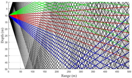
Multiray path geometry. The red, green, blue, and black lines indicate the direct, surface-reflected, bottom-reflected, and paths reflected at both boundaries, respectively
2.1 BELLHOP-based transmission loss model
The BELLHOP model, a ray-tracing-based underwater channel model, can consider various environmental variables, such as the positions of source and receivers, distribution of sound velocity, shape of the surface, structure, and characteristics of the subsurface. To obtain a transmission loss model, the BELL-HOP model assumes that receivers are located at each position in an area where the transmission loss from the transmission point of a source with a specific frequency is to be obtained. At each receiver position, the time-delay and amplitude information due to multipaths are calculated. Based on such information, a transmission loss model due to multipaths is implemented by calculating the phase change and intensity of the source for a specific frequency.
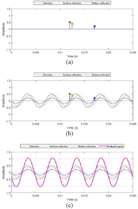
The transmission loss values obtained using the BELLHOP model can be represented as shown in Figure 2. In the figure, the process of the BELLHOP model performed in the frequency domain is shown in the time domain. Figure 2 (a) shows the time-delay and amplitude information calculated at a specific position, and Figure 2 (b) shows the sine signal of a specific frequency expressed based on the information. Figure 2 (c) shows the signal yielded by synthesizing those obtained along the multipaths. As shown in Figure 2, the transmission loss model obtained using the BELLHOP model expresses the signals of a specific frequency at all times, including the specific delayed time, because the phase change and intensity values of the source are calculated based on the time-delay and amplitude information at a specific position. The BELLHOP model can implement a transmission loss model that considers various environmental variables for a single frequency. However, it is extremely difficult to implement an accurate transmission loss model for a source used in the underwater acoustic environment, because it has a certain frequency band as well as the dominant frequency.
2.2 Transmission loss model based on the wave equation
In this study, the linear wave equation derived from the equations of motion, continuity, and state were analyzed to obtain a transmission loss model that considers the coherence signal characteristics due to multipaths. Equation (4) below represents the three-dimensional (3D) linear wave equation in acoustic media [9]–[10].
| (4) |
where P is the pressure wavefield, C is the P-wave velocity of the medium, f and is the source. Wave propagation modeling was performed by applying the central difference method of the finite difference equation for the time domain to the above equation, as follows:
| (5) |
where L is the finite difference Laplacian operator and Δ t is the sampling interval. In this study, numerical modeling in the time domain was performed by analyzing the second-order derivative term of the Laplacian operator with the accuracy of the 14th-order coefficient to acquire the pressure field at each grid position.
The data acquired through numerical modeling based on the above wave equation are time-series data on the pressure wavefield in the acoustic medium. To construct a transmission loss model using the data, it is necessary to convert the acquired pressure field into acoustic wave intensity. The transmission loss can be obtained using the acoustic wave intensity as follows.
| (6) |
where TLk is the transmission loss value at position k, I1m is the acoustic wave intensity measured at a radius of approximately 1 m from the source, and Ik is the acoustic wave intensity measured at position k. The transmission loss model obtained using the acoustic wave intensity represents the degree of loss of the acoustic wave intensity with respect to the distance. In this study, the acoustic wave intensity at an arbitrary position was selected and used as the maximum value of the time-series data at the corresponding point. Based on this, the transmission loss was expressed as follows:
| (7) |
where max[P(xi,yj,zk)] and max[P(x1m,y1m,z1m)] and are the maximum value of the pressure field located at the 3D coordinates (x, j, k)and that of the pressure field acquired at a radius of 1 m from the source. As the pressure field was calculated in the 3D spherical propagation environment, the spreading factor Sf was set to 20.
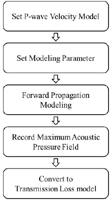
In this study, a coherence transmission loss model was obtained by analyzing the linear wave equation with the finite difference equation. This work flow is shown in Figure 3. First, to obtain a transmission loss model, a velocity model for the sound velocity structure, surface, and subsurface models is defined for the underwater acoustic environment to be simulated. Second, modeling parameters are defined according to the frequency of the source to be used and the velocity model. Third, modeling is performed using the velocity model and source, and the maximum pressure field at each grid position defined in the underwater acoustic environment is recorded. Finally, a transmission loss model can be created by substituting the maximum pressure field recorded at each grid position and that obtained at a radius of 1 m from the source into Equation (7). When numerical modeling is performed by analyzing the linear wave equation with the finite difference equation, it is possible to directly calculate various aspects of a wave propagating from a source, including reflection, scattering, and dispersion phenomena. However, the computational cost increases exponentially with the size of the field to be observed, owing to the direct calculation of wave propagation.
3. Comparison of Transmission Loss Models
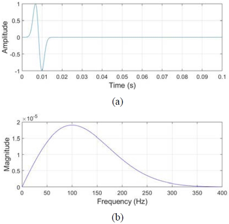
For the comparison of the transmission loss models implemented using the pressure field information, which was obtained through the numerical analysis of the wave equation with the FDM, the transmission loss values for spherical propagation without multipaths were compared with the BELLHOP model in the constant-velocity model. The underwater acoustic environment was assumed to be a homogeneous environment of 1500m/s. Regarding the water depth, the point at which the surface reflection wave and the signal of the source are clearly reinforced or canceled and that at which they are separated are selected as 10 and 20 m, respectively. A source with a frequency band was used instead of a sine signal with a single frequency, as shown in Figure 4. The maximum frequency of the source was 400 Hz, and its dominant frequency was 100 Hz.
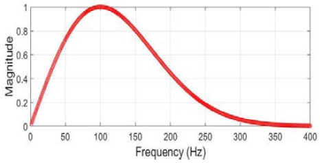
As BELLHOP calculates the transmission loss for a specific single frequency, an accurate comparison with the results obtained through the numerical analysis of the wave equation is extremely difficult for a source with a frequency band. In this study, for an accurate comparison with the BELLHOP model, a transmission loss model was implemented at intervals of 1 Hz for frequencies up to 400 Hz in the frequency spectrum of the source. The results of the frequency spectrum were normalized as shown in Figure 5 and applied as weights.
Figures 6 (a) and 6 (c) show the transmission loss models obtained at water depths of 10 and 20 m using the dominant frequency of 100 Hz as a source through the BELLHOP model, and Figures 6 (b) and 6d show the transition loss models that considered the frequency spectrum of the source used. In the case of the models that used a single-frequency source as shown in Figures 6 (a) and 6 (c), the characteristics of a continuous wave were observed rather than those of a single-period signal as shown in Figure 4 (a). Additionally, the transmission loss models obtained using a single frequency exhibited coherence characteristics, owing to the constructive and destructive interference of the surface-reflected and direct waves according to the water depth. When the frequency band of the source was used as shown in Figure 6 (b) and 6 (d), transmission loss models that reflected the coherence characteristics due to the propagation of the source used could be obtained, because the signals of a single frequency were added according to the weight.

BELLHOP transmission loss model at source depth 10 m: (a) 100 Hz, (b) 1–400 Hz; source depth 20 m: (c) 100 Hz, (d) 1–400 Hz
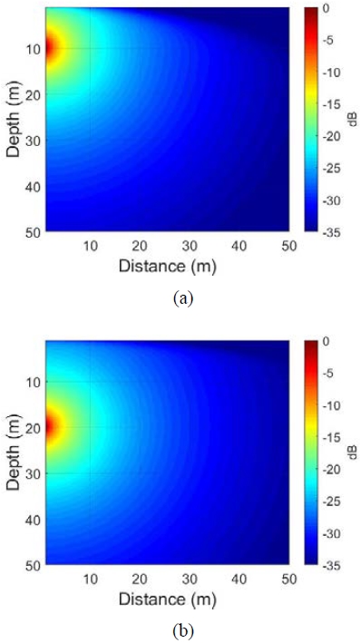
Figure 7 shows the transmission loss models obtained through the wave equation. They exhibited coherence characteristics that reflected the frequency characteristics of the source, as shown in Figures 6 (b) and 6 (d), because numerical modeling was performed using the characteristics of the source according to the frequency band.
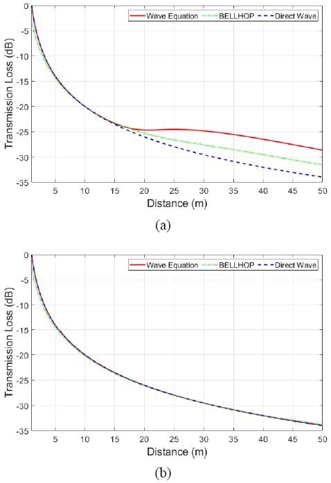
For an accurate analysis, the horizontal direction was compared according to the source depth. Figure 8 shows the result of comparing the transmission loss calculated by BELLHOP, the wave equation, and Equation (3) for each source depth. When the transmission loss models obtained at different source depths were compared, the transmission losses obtained through BELLHOP and the wave equation numerical analysis were different at a source depth of 10 m, owing to the constructive and destructive interference caused by the surface reflection wave. At a source depth of 20 m, the results were similar to the transmission loss results due to the direct wave, because the influence of the constructive and destructive interference caused by the surface reflection wave was smaller. To examine the difference between the transmission loss models implemented based on BELLHOP and the wave equation, considering source depths of 10 and 20 m, the transmission loss values at a horizontal distance of 40 m from the source position were compared (Table 1). When the source depth was 10 m, the transmission loss based on the wave equation was relatively high. This is because the influence of the constructive interference signal caused by multipaths was stronger, as the transmission loss model based on BELLHOP was implemented using the root mean square value at the receiver point, and the transmission loss model based on the wave equation was implemented using the maximum value (zero-to-peak). When the source depth was 20 m, both methods exhibited similar values, because there was no interference between the direct and surface reflection waves.
4. Conclusion
In this study, a coherence transmission loss model was implemented through the numerical analysis of the wave equation, which is one of the methods used to simulate the acoustic wave transmission phenomenon due to source propagation in the underwater acoustic environment, using the FDM. The implemented transmission loss model exhibited coherence characteristics considering complex frequency characteristics.
The model was implemented using the acoustic wave intensity at a specific position, which was calculated as the maximum pressure field at the position. Based on this method, it was confirmed that the values obtained from spherical propagation were similar to those obtained using the BELLHOP model in areas without multipaths. In multipath areas, different values were confirmed owing to the constructive and destructive interference between the direct and surface-reflected waves. This was due to the use of different transmission loss measurement methods and a difference in the attenuation phenomenon for the frequency used.
The computational cost requirements exponentially increase with the size of the field. Although the practical application of this work is very difficult, this study is significant in that it implemented a coherence transmission loss model based on the wave equation. If the propagation pattern of a source is simulated for a broader field in the future with advances in computer technology, the resulting accurate coherence transmission loss model can improve the detection performance of sonar equipment and can be used to implement accurate target detection tools.
Acknowledgments
The BELLHOP model provided by the Ocean Acoustics Library was used in this research. This research was supported by the Agency for Defense Development (contract number: UD190001DD).
Author Contributions
Conceptualization, D. W. Lee and W. K. Chung; Methodology, D. W. Lee and H. S. Bae; Software, D. W. Lee and W. S. Kim; Validation, D. W. Lee, H. S. Bae, and W. S. Kim and W. K. Chung; Formal Analysis, D. W. Lee; Investigation, D. W. Lee; Data Curation, D. W. Lee and H. S. Bae; Writing—Original Draft Preparation, D. W. Lee; Writing—Review & Editing, H. S. Bae, W. S. Kim and W. K. Chung; Visualization, D. W. Lee and W. S. Kim; Supervision, W. K. Chung; Project Administration, H. S. Bae ; Funding Acquisition, W. K. Chung.
References
-
D. H. Gwon, J. W. Kim, M. H. Kim, H. G. Park, T. Y. Kim, and A. Y. Kim, "Development of a side scan sonar module for the underwater simulator," 14th International Conference on Ubiquitous Robots and Ambient Intelligence, pp. 662-665, 2017.
[https://doi.org/10.1109/URAI.2017.7992789]

-
Y. J. Lee, J. H. Lee, and H. T. Choi, “A framework of recognition and tracking for underwater objects based on sonar images: part 1. design and recognition of artificial landmark considering characteristics of sonar images,” Journal of The Institute of Electronics and Information Engineers, vol. 51, no. 2, pp. 182-189, 2014.
[https://doi.org/10.5573/ieie.2014.51.2.182]

- S. L. Maxwell and N. E. Gove, The Feasibility of Estimating Migrating Salmon Passage Rates in Turbid Rivers Using a Dual Frequency Identification Sonar,” Regional Information Report 1 No. 2A04-05, Alaska Department of Fish and Game Division of Commercial Fisheries, U.S., 2004.
- B. Li, W. An, J. Li, Y. Zhao, X. Shi, and W. Wang, "Application of side scan sonar in the detection of sunken oil in shallow sea," International Geophysical Conference, Qingdao, China, 17-20 April 2017, pp. 886-889, 2017.
- G. M. Kim, “Covert underwater acoustic communication,” The Journal of Korean Institute of Communications and Information Sciences, vol. 33, no. 8, pp. 82-88, 2016 (in Korean).
- J. H. Kim, T. H. Bok, J. H. Bae, D. G. Paeng, C. H. Lee, and S. I. Kim, “Communication performance analysis according to seasons in West Sea,” Journal of the Institute of Electronics and Information Engineers of Korea TC, vol. 48, no. 1, pp. 9-15, 2011 (in Korean).
- M. B. Porter, The Bellhop Manual and User’s Guide: Preliminary Draft, Heat, Light, and Sound Research, Inc., La Jolla, CA, USA, 2011. Available: https://oalib-acoustics.org/AcousticsToolbox/Bellhop-2010-1.pdf, .
-
W. C. Knight, R. G. Pridham, and S. M. Kay, “Digital signal processing for sonar,” Proceedings of the IEEE, vol. 69, no. 11, pp. 1451-1506, 1981.
[https://doi.org/10.1109/PROC.1981.12186]

-
S. P. Näsholm and S. Holm, "On a fractional zener elastic wave equation," Fractional Calculus and Applied Analysis, vol. 16, pp. 26-50, 2013.
[https://doi.org/10.2478/s13540-013-0003-1]

- Richard Feynman, The Feynman Lectures on Physics, vol 1, Boston, U. S.: Addison-Wesley, 1969.

